1
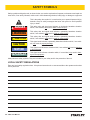
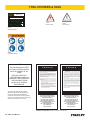
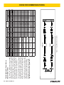
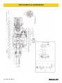
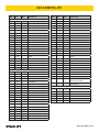
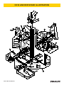
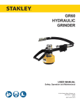
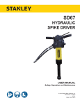
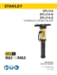
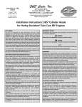
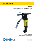
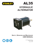
CD12
Hydraulic
Core Drill
USER MANUAL
Safety, Operation and Maintenance
© 2014 Stanley Black & Decker, Inc.
New Britain, CT 06053
U.S.A.
62379 8/2014 Ver. 4
TABLE OF CONTENTS
SAFETY SYMBOLS...................................................................................................................................................4
SAFETY PRECAUTIONS...........................................................................................................................................5
TOOL STICKERS & TAGS.........................................................................................................................................6
HOSE TYPES.............................................................................................................................................................7
HOSE RECOMMENDATIONS...................................................................................................................................8
FIGURE 1. TYPICAL HOSE CONNECTIONS........................................................................................................8
HTMA REQUIREMENTS............................................................................................................................................9
OPERATION.............................................................................................................................................................10
ANCHOR STAND TROUBLESHOOTING................................................................................................................13
TOOL PROTECTION & CARE.................................................................................................................................14
TROUBLESHOOTING.............................................................................................................................................15
MAINTENANCE.......................................................................................................................................................16
SPECIFICATIONS....................................................................................................................................................17
ACCESSORIES.......................................................................................................................................................17
SERVICE PARTS.....................................................................................................................................................17
CD12 PARTS ILLUSTRATION.................................................................................................................................18
CD12 PARTS LIST...................................................................................................................................................19
CD12 ANCHOR STAND ILLUSTRATION................................................................................................................20
CD12 ANCHOR STAND PARTS LIST......................................................................................................................21
IMPORTANT
To fill out a Product Warranty Validation form, and for information on your warranty,
visit Stanleyhydraulics.com and select the Company tab, Warranty.
(NOTE: The warranty Validation record must be submitted to validate the warranty).
SERVICING: This manual contains safety, operation, and routine maintenance instructions. Stanley Hydraulic Tools
recommends that servicing of hydraulic tools, other than routine maintenance, must be performed by an authorized
and certified dealer. Please read the following warning.
WARNING
SERIOUS INJURY OR DEATH COULD RESULT FROM THE IMPROPER REPAIR OR
SERVICE OF THIS TOOL.
REPAIRS AND / OR SERVICE TO THIS TOOL MUST ONLY BE DONE BY AN
AUTHORIZED AND CERTIFIED DEALER.
For the nearest authorized and certified dealer, call Stanley Hydraulic Tools at the number listed on the back of this
manual and ask for a Customer Service Representative.
CD12 User Manual ◄ 3
SAFETY SYMBOLS
Safety symbols and signal words, as shown below, are used to emphasize all operator, maintenance and repair actions which, if not strictly followed, could result in a life-threatening situation, bodily injury or damage to equipment.
This is the safety alert symbol. It is used to alert you to potential personal injury
hazards. Obey all safety messages that follow this symbol to avoid possible
injury or death.
DANGER
This safety alert and signal word indicate an imminently hazardous situation
which, if not avoided, will result in death or serious injury.
WARNING
This safety alert and signal word indicate a potentially hazardous situation
which, if not avoided, could result in death or serious injury.
CAUTION
This safety alert and signal word indicate a potentially hazardous situation
which, if not avoided, could result in death or serious injury.
CAUTION
This signal word indicates a potentially hazardous situation which, if not avoided, may result in property damage.
NOTICE
This signal word indicates a situation which, if not avoided, will result in damage
to the equipment.
IMPORTANT
This signal word indicates a situation which, if not avoided, may result in damage to the equipment.
Always observe safety symbols. They are included for your safety and for the protection of the tool.
LOCAL SAFETY REGULATIONS
Enter any local safety regulations here. Keep these instructions in an area accessible to the operator and maintenance personnel.
4 ► CD12 User Manual
SAFETY PRECAUTIONS
Tool operators and maintenance personnel must always
comply with the safety precautions given in this manual,
and on the stickers and tags attached to or on the tool
and hose(s).
These safety precautions are for your safety. Review
them carefully before operating the tool or performing
any maintenance or repairs.
Supervising personnel may specify additional precautions for your work area to comply with company policies
and local safety regulations. Enter any added precautions in the space provided in this manual.
The CD12 Hydraulic Core Drill will provide safe and
dependable service if operated in accordance with the
instructions given in this manual. Read and understand
this manual and any stickers and tags attached to the
tool and hoses before operation. Failure to do so could
result in personal injury or equipment damage.
•
Operator must start in a work area without bystanders. Flying debris can cause serious injury.
•
The operator must be familiar with all prohibited
work areas such as excessive slopes and dangerous terrain conditions.
•
Establish a training program for all operators to ensure safe operations.
•
Do not operate the tool unless thoroughly trained or
under the supervision of an instructor.
•
Always wear safety equipment such as goggles,
head protection, and safety shoes at all times when
operating the tool.
•
Do not inspect or clean the tool while the hydraulic
power source is connected. Accidental engagement
of the tool can cause serious injury.
•
Do not operate this tool without first reading the Operating Instructions.
•
Never operate the tool if you cannot be sure that
underground utilities are not present. Underground
electrical utilities present an electrocution hazard.
Underground gas utilities present an explosion hazard. Other underground utilities may present other
hazards.
•
Do not wear loose fitting clothing when operating the
tool. Loose fitting clothing can get entangled with the
tool and cause serious injury.
•
Supply hoses must have a minimum working pressure rating of 2500 psi/175 bar.
•
Be sure all hose connections are tight.
•
The hydraulic circuit control valve must be in the
OFF position when coupling or uncoupling the tool.
Wipe all couplers clean before connecting. Failure
to do so may result in damage to the quick couplers
and cause overheating. Use only lint-free cloths.
•
Do not operate the tool at oil temperatures above
140 °F/60 °C. Operation at higher oil temperatures
can cause operator discomfort and may cause damage to the tool.
•
Do not operate a damaged, improperly adjusted, or
incompletely assembled tool.
•
To avoid personal injury or equipment damage, all
tool repair, maintenance and service must only be
performed by authorized and properly trained personnel.
•
Do not exceed the rated limits of the tool or use the
tool for applications beyond its design capacity.
•
Always keep critical tool markings, such as labels
and warning stickers legible.
•
Always replace parts with replacement parts recommended by Stanley Hydraulic Tools.
•
Check fastener tightness often and before each use
daily.
•
Warning: Use of this tool on certain materials during
demolition could generate dust potentially containing a variety of hazardous substances such as asbestos, silica or lead. Inhalation of dust containing
these or other hazardous substances could result
in serious injury, cancer or death. Protect yourself
and those around you. Research and understand
the materials you are cutting. Follow correct safety
procedures and comply with all applicable national,
state or provisional health and safety regulations
relating to them, including, if appropriate arranging
for the safe disposal of the materials by a qualified
person.
CD12 User Manual ◄ 5
TOOL STICKERS & TAGS
Stanley Hydraulic Tools
3810 SE Naef Road
Milwaukie, OR 97267
Model No.
CD12
D
CAUTION
30 LPM @ 138 B AR
EHTMA CATEGORY
11207
Circuit Type D
11206
Circuit Type C
65139
CD12 Name Tag
28409
Composite Sticker
NOTE:
THE INFORMATION LISTED
ON THE STICKERS SHOWN,
MUST BE LEGIBLE AT ALL
TIMES.
REPLACE DECALS IF
THEY BECOME WORN OR
DAMAGED. REPLACEMENTS
ARE AVAILABLE FROM
YOUR LOCAL STANLEY
DISTRIBUTOR.
The safety tag (P/N 15875) at right is
attached to the tool when shipped from
the factory. Read and understand the
safety instructions listed on this tag before
removal. We suggest you retain this tag and
attach it to the tool when not in use.
D A N G E R
1.
FAILURE TO USE HYDRAULIC HOSE LABELED AND CERTIFIED AS NON-CONDUCTIVE WHEN USING HYDRAULIC
TOOLS ON OR NEAR ELECTRICAL LINES MAY RESULT IN
DEATH OR SERIOUS INJURY.
BEFORE USING HOSE LABELED AND CERTIFIED AS NONCONDUCTIVE ON OR NEAR ELECTRIC LINES BE SURE THE
HOSE IS MAINTAINED AS NON-CONDUCTIVE. THE HOSE
SHOULD BE REGULARLY TESTED FOR ELECTRIC CURRENT LEAKAGE IN ACCORDANCE WITH YOUR SAFETY
DEPARTMENT INSTRUCTIONS.
2.
A HYDRAULIC LEAK OR BURST MAY CAUSE OIL INJECTION INTO THE BODY OR CAUSE OTHER SEVERE
PERSONAL INJURY.
A.
DO NOT EXCEED SPECIFIED FLOW AND PRESSURE
FOR THIS TOOL. EXCESS FLOW OR PRESSURE MAY
CAUSE A LEAK OR BURST.
B.
DO NOT EXCEED RATED WORKING PRESSURE OF
HYDRAULIC HOSE USED WITH THIS TOOL. EXCESS
PRESSURE MAY CAUSE A LEAK OR BURST.
C. CHECK TOOL HOSE COUPLERS AND CONNECTORS
DAILY FOR LEAKS. DO NOT FEEL FOR LEAKS WITH
YOUR HANDS. CONTACT WITH A LEAK MAY RESULT
IN SEVERE PERSONAL INJURY.
D A N G E R
D. DO NOT LIFT OR CARRY TOOL BY THE HOSES. DO
NOT ABUSE HOSE. DO NOT USE KINKED, TORN OR
DAMAGED HOSE.
3.
MAKE SURE HYDRAULIC HOSES ARE PROPERLY CONNECTED TO THE TOOL BEFORE PRESSURING SYSTEM.
SYSTEM PRESSURE HOSE MUST ALWAYS BE CONNECTED TO TOOL “IN” PORT. SYSTEM RETURN HOSE
MUST ALWAYS BE CONNECTED TO TOOL “OUT” PORT.
REVERSING CONNECTIONS MAY CAUSE REVERSE
TOOL OPERATION WHICH CAN RESULT IN SEVERE
PERSONAL INJURY.
4.
DO NOT CONNECT OPEN-CENTER TOOLS TO CLOSEDCENTER HYDRAULIC SYSTEMS. THIS MAY RESULT IN
LOSS OF OTHER HYDRAULIC FUNCTIONS POWERED BY
THE SAME SYSTEM AND/OR SEVERE PERSONAL INJURY.
5.
BYSTANDERS MAY BE INJURED IN YOUR WORK AREA.
KEEP BYSTANDERS CLEAR OF YOUR WORK AREA.
6.
WEAR HEARING, EYE, FOOT, HAND AND HEAD PROTECTION.
7.
TO AVOID PERSONAL INJURY OR EQUIPMENT DAMAGE,
ALL TOOL REPAIR MAINTENANCE AND SERVICE MUST
ONLY BE PERFORMED BY AUTHORIZED AND PROPERLY
TRAINED PERSONNEL.
I M P O R T A N T
I M P O R T A N T
READ OPERATION MANUAL AND
SAFETY INSTRUCTIONS FOR THIS
TOOL BEFORE USING IT.
READ OPERATION MANUAL AND
SAFETY INSTRUCTIONS FOR THIS
TOOL BEFORE USING IT.
USE ONLY PARTS AND REPAIR
PROCEDURES APPROVED BY
STANLEY AND DESCRIBED IN THE
OPERATION MANUAL.
USE ONLY PARTS AND REPAIR
PROCEDURES APPROVED BY
STANLEY AND DESCRIBED IN THE
OPERATION MANUAL.
TAG TO BE REMOVED ONLY BY
TOOL OPERATOR.
TAG TO BE REMOVED ONLY BY
TOOL OPERATOR.
SEE OTHER SIDE
SEE OTHER SIDE
SAFETY TAG P/N 15875 (Shown smaller then actual size)
6 ► CD12 User Manual
HOSE TYPES
The rated working pressure of the hydraulic hose must be equal to or higher than the relief valve setting on the hydraulic system. There are three types of hydraulic hose that meet this requirement and are authorized for use with
Stanley Hydraulic Tools. They are:
Certified non-conductive — constructed of thermoplastic or synthetic rubber inner tube, synthetic fiber braid
reinforcement, and weather resistant thermoplastic or synthetic rubber cover. Hose labeled certified nonconductive is the only hose authorized for use near electrical conductors.
Wire-braided (conductive) — constructed of synthetic rubber inner tube, single or double wire braid reinforcement, and weather resistant synthetic rubber cover. This hose is conductive and must never be used near
electrical conductors.
Fabric-braided (not certified or labeled non-conductive) — constructed of thermoplastic or synthetic rubber inner tube, synthetic fiber braid reinforcement, and weather resistant thermoplastic or synthetic rubber cover. This
hose is not certified non-conductive and must never be used near electrical conductors.
HOSE SAFETY TAGS
To help ensure your safety, the following DANGER tags are attached to all hose purchased from Stanley Hydraulic
Tools. DO NOT REMOVE THESE TAGS.
If the information on a tag is illegible because of wear or damage, replace the tag immediately. A new tag may be
obtained from your Stanley Distributor.
D A N G E R
D A N G E R
1.
FAILURE TO USE HYDRAULIC HOSE LABELED AND CERTIFIED AS NON-CONDUCTIVE
WHEN USING HYDRAULIC TOOLS ON OR NEAR ELECTRIC LINES MAY RESULT IN
DEATH OR SERIOUS INJURY.
FOR PROPER AND SAFE OPERATION MAKE SURE THAT YOU HAVE BEEN PROPERLY TRAINED IN CORRECT PROCEDURES REQUIRED FOR WORK ON OR AROUND
ELECTRIC LINES.
2.
BEFORE USING HYDRAULIC HOSE LABELED AND CERTIFIED AS NON-CONDUCTIVE
ON OR NEAR ELECTRIC LINES. WIPE THE ENTIRE LENGTH OF THE HOSE AND FITTING WITH A CLEAN DRY ABSORBENT CLOTH TO REMOVE DIRT AND MOISTURE AND
TEST HOSE FOR MAXIMUM ALLOWABLE CURRENT LEAKAGE IN ACCORDANCE WITH
SAFETY DEPARTMENT INSTRUCTIONS.
3.
DO NOT EXCEED HOSE WORKING PRESSURE OR ABUSE HOSE. IMPROPER USE
OR HANDLING OF HOSE COULD RESULT IN BURST OR OTHER HOSE FAILURE.
KEEP HOSE AS FAR AWAY AS POSSIBLE FROM BODY AND DO NOT PERMIT DIRECT
CONTACT DURING USE. CONTACT AT THE BURST CAN CAUSE BODILY INJECTION
AND SEVERE PERSONAL INJURY.
4.
HANDLE AND ROUTE HOSE CAREFULLY TO AVOID KINKING, ABRASION, CUTTING, OR
CONTACT WITH HIGH TEMPERATURE SURFACES. DO NOT USE IF KINKED. DO NOT
USE HOSE TO PULL OR LIFT TOOLS, POWER UNITS, ETC.
5.
CHECK ENTIRE HOSE FOR CUTS CRACKS LEAKS ABRASIONS, BULGES, OR DAMAGE TO COUPLINGS IF ANY OF THESE CONDITIONS EXIST, REPLACE THE HOSE
IMMEDIATELY. NEVER USE TAPE OR ANY DEVICE TO ATTEMPT TO MEND THE HOSE.
6.
AFTER EACH USE STORE IN A CLEAN DRY AREA.
SEE OTHER SIDE
SIDE 1
SEE OTHER SIDE
(Shown smaller than actual size)
DO NOT REMOVE THIS TAG
DO NOT REMOVE THIS TAG
THE TAG SHOWN BELOW IS ATTACHED TO “CERTIFIED NON-CONDUCTIVE” HOSE
SIDE 2
D A N G E R
D A N G E R
1.
DO NOT USE THIS HYDRAULIC HOSE ON OR NEAR ELECTRIC LINES. THIS HOSE IS
NOT LABELED OR CERTIFIED AS NON-CONDUCTIVE. USING THIS HOSE ON OR NEAR
ELECTRICAL LINES MAY RESULT IN DEATH OR SERIOUS INJURY.
5.
CHECK ENTIRE HOSE FOR CUTS CRACKS LEAKS ABRASIONS, BULGES, OR DAMAGE TO
COUPLINGS IF ANY OF THESE CONDITIONS EXIST, REPLACE THE HOSE IMMEDIATELY.
NEVER USE TAPE OR ANY DEVICE TO ATTEMPT TO MEND THE HOSE.
2.
FOR PROPER AND SAFE OPERATION MAKE SURE THAT YOU HAVE BEEN PROPERLY
TRAINED IN CORRECT PROCEDURES REQUIRED FOR WORK ON OR AROUND ELECTRIC LINES.
6.
AFTER EACH USE STORE IN A CLEAN DRY AREA.
3.
DO NOT EXCEED HOSE WORKING PRESSURE OR ABUSE HOSE. IMPROPER USE OR
HANDLING OF HOSE COULD RESULT IN BURST OR OTHER HOSE FAILURE. KEEP HOSE
AS FAR AWAY AS POSSIBLE FROM BODY AND DO NOT PERMIT DIRECT CONTACT
DURING USE. CONTACT AT THE BURST CAN CAUSE BODILY INJECTION AND SEVERE
PERSONAL INJURY.
4.
HANDLE AND ROUTE HOSE CAREFULLY TO AVOID KINKING, CUTTING, OR CONTACT
WITH HIGH TEMPERATURE SURFACES. DO NOT USE IF KINKED. DO NOT USE HOSE TO
PULL OR LIFT TOOLS, POWER UNITS, ETC.
DO NOT REMOVE THIS TAG
DO NOT REMOVE THIS TAG
THE TAG SHOWN BELOW IS ATTACHED TO “CONDUCTIVE” HOSE.
SEE OTHER SIDE
SEE OTHER SIDE
SIDE 1
SIDE 2
(Shown smaller than actual size)
CD12 User Manual ◄ 7
8 ► CD12 User Manual
All hydraulic hose must meet or exceed
specifications as set forth by SAE J517.
All hydraulic hose must have at least a rated
minimum working pressure equal to the maximum hydraulic system relief valve setting.
This chart is intended to be used for hydraulic
tool applications only based on Stanley Hydraulic Tools tool operating requirements and
should not be used for any other applications.
The chart to the right shows recommended
minimum hose diameters for various hose
lengths based on gallons per minute (gpm)/
liters per minute (lpm). These recommendations are intended to keep return line pressure
(back pressure) to a minimum acceptable level to ensure maximum tool performance.
Tool to Hydraulic Circuit Hose
Recommendations
15-34
MM
Inside Diameter
INCH
USE
(Press/Return)
PSI
up to 10
up to 3
3/8
10
Both
2250
49-60
13-16
FLOW >>>
RETURN
<<< FLOW
PRESSURE
26-100
up to 25
100-200
51-100
up to 50
100-300
51-100
up to 50
26-100
up to 25
8-30
up to 8
30-60
15-30
up to 15
30-90
15-30
up to 15
7.5-30
up to 7.5
Figure 1. Typical Hose Connections
49-60
38-49
10-13
13-16
19-40
5-10.5
38-49
19-40
5-10.5
10-13
19-40
5-10.5
38-49
15-23
10-13
15-23
4-6
19
25.4
16
19
19
25.4
5/8
3/4
3/4
1
19
3/4
1
16
3/4
16
19
3/4
5/8
16
5/8
5/8
16
13
13
10
5/8
1/2
1/2
3/8
Return
Pressure
Return
Pressure
Return
Pressure
Return
Pressure
Both
Return
Pressure
Both
Both
Both
Both
2500
2500
2500
2500
2500
2500
2500
2500
2500
2500
2500
2500
2500
2500
2500
175
175
175
175
175
175
175
175
175
175
175
175
175
175
175
155
BAR
Min. Working Pressure
Certified Non-Conductive Hose - Fiber Braid - for Utility Bucket Trucks
METERS
Hose Lengths
FEET
Conductive Hose - Wire Braid or Fiber Braid -DO NOT USE NEAR ELECTRICAL CONDUCTORS
4-6
4-9
LPM
Oil Flow
GPM
HOSE RECOMMENDATIONS
HTMA / EHTMA REQUIREMENTS
HTMA / EHTMA REQUIREMENTS
HTMA
HYDRAULIC SYSTEM REQUIREMENTS
TYPE I
Nominal Operating Pressure
(at the power supply outlet)
4-6 gpm
(15-23 lpm)
1500 psi
(103 bar)
TOOL TYPE
TYPE II
TYPE RR
7-9 gpm
(26-34 lpm)
1500 psi
(103 bar)
9-10.5 gpm
(34-40 lpm)
1500 psi
(103 bar)
System relief valve setting
(at the power supply outlet)
2100-2250 psi
(145-155 bar)
2100-2250 psi
(145-155 bar)
2200-2300 psi
(152-159 bar)
2100-2250 psi
(145-155 bar)
Maximum back pressure
(at tool end of the return hose)
250 psi
(17 bar)
250 psi
(17 bar)
250 psi
(17 bar)
250 psi
(17 bar)
Measured at a max. fluid viscosity of:
(at min. operating temperature)
400 ssu*
400 ssu*
400 ssu*
400 ssu*
(82 centistokes) (82 centistokes) (82 centistokes) (82 centistokes)
Temperature: Sufficient heat rejection
capacity to limit max. fluid temperature to:
(at max. expected ambient temperature)
140° F
(60° C)
Flow Range
140° F
(60° C)
140° F
(60° C)
TYPE III
11-13 gpm
(42-49 lpm)
1500 psi
(103 bar)
140° F
(60° C)
3 hp
5 hp
6 hp
7 hp
Min. cooling capacity at a temperature
(2.24 kW)
(3.73 kW)
(5.22 kW)
(4.47 kW)
difference of between ambient and fluid
40° F
40° F
40° F
40° F
temps
(22° C)
(22° C)
(22° C)
(22° C)
NOTE:
Do not operate the tool at oil temperatures above 140° F (60° C). Operation at higher temperatures can cause operator
discomfort at the tool.
Filter
Min. full-flow filtration
Sized for flow of at least:
(For cold temp. startup and max.
dirt-holding capacity)
25 microns
30 gpm
(114 lpm)
Hydraulic fluid Petroleum based
(premium grade, anti-wear, non-conductive)
Viscosity (at min. and max. operating temps)
100-400 ssu*
25 microns
30 gpm
(114 lpm)
25 microns
30 gpm
(114 lpm)
100-400 ssu*
100-400 ssu*
(20-82 centistokes)
25 microns
30 gpm
(114 lpm)
100-400 ssu*
NOTE:
When choosing hydraulic fluid, the expected oil temperature extremes that will be experienced in service determine the
most suitable temperature viscosity characteristics. Hydraulic fluids with a viscosity index over 140 will meet the requirements
over a wide range of operating temperatures.
*SSU = Saybolt Seconds Universal
EHTMA
HYDRAULIC SYSTEM
REQUIREMENTS
CLASSIFICATION
B
C
D
Nominal Operating Pressure
(at the power supply outlet)
3.5-4.3 gpm
(13.5-16.5 lpm)
1870 psi
(129 bar)
4.7-5.8 gpm
(18-22 lpm)
1500 psi
(103 bar)
7.1-8.7 gpm
(27-33 lpm)
1500 psi
(103 bar)
9.5-11.6 gpm
(36-44 lpm)
1500 psi
(103 bar)
11.8-14.5 gpm
(45-55 lpm)
1500 psi
(103 bar)
System relief valve setting
(at the power supply outlet)
2495 psi
(172 bar)
2000 psi
(138 bar)
2000 psi
(138 bar)
2000 psi
(138 bar)
2000 psi
(138 bar)
Flow Range
NOTE: These are general hydraulic system requirements. See tool specification page for tool specific requirements
CD12 User Manual ◄ 9
OPERATION
GENERAL OPERATION
CHECK THE POWER SOURCE
The tool comes with a set of accessories which may be
customized by each purchaser, so as to facilitate performance of all work occurring within the scope of his
specific application. Tools included are for mounting and
dismounting.
1. Using a calibrated flowmeter and pressure gauge,
check that the hydraulic power source develops a
flow of 7–9 gpm/26–34 lpm at 950–2000 psi/66–138
bar.
•
•
•
•
Single-head wrench
Single-head wrench
Single-head wrench
Hex wrench
SW 24
SW 32
SW 41
SW 5
2. Make sure the hydraulic power source is equipped
with a relief valve set to open at 2100–2250 psi/145–
155 bar.
3. Check that the hydraulic circuit matches the tool for
open-center (OC) operation.
DRILL BIT INSTALLATION
CHECK THE TOOL
1. Make certain all tool accessories are correctly installed. Failure to install tool accessories properly
can result in damage to the tool or personal injury.
WARNING
Before you start changing the drill bit, make sure that
the tool is disconnected from the power source in
order to avoid unintentional operation of the tool and
injury.
Use a single-head wrench SW 24 (small drill bit) or SW
41 (large drill bits) and a single-head wrench SW 32 to
manually unscrew the drill bit to be removed and to
screw on the new one. There is no need to use any additional tools.
DIMENSION OF THE DRILL BIT
Drill head thread: male 1 – 1/4 in. UNC and female R
1/2 in.
2. Check the equipment for signs of oil leaks. If leaks
are observed, do not use the tool; have the equipment serviced before use.
3. Check fasteners for tightness.
4. Check the tool and hydraulic system for proper operation and performance.
5. If the equipment does not appear to operate properly, have it serviced before use.
CONNECT HOSES
1. Wipe all hose couplers with a clean lint-free cloth
before making connections.
Gear #1
Gear #2
Gear #3
2. Connect the hoses from the hydraulic power source
to the tool fittings or quick disconnects. It is good
practice to connect the return hose first and disconnect it last to eliminate or reduce trapped pressure
for easier quick-connect fitting attachment.
Speed (1/min)
610
1440
2880
NOTE:
Drill bit dia. (mm)
100–162 40–100
20–40
Cutting speed (m/s)
3.2–5.6
3.2–6.4
If uncoupled hoses are left in the sun, pressure increase within the hoses can make them difficult to
connect. When ever possible, connect the free ends
of hoses together.
Which drill bit at which speed?
3.2–7.2
3. Observe the flow indicators stamped on the hose
couplers to ensure that the flow is in the proper direction. The female coupler on the drill is the inlet
coupler.
4. Cycle the control valve momentarily. If the drill does
not operate, the hoses might be reversed. Verify
correct connection of the hoses before continuing.
10 ► CD12 User Manual
OPERATION
DRILLING WITH CD12 ANCHOR
STAND
The anchor stand may be used with a vacuum pump for
a vacuum hold down or with a concrete anchor screw to
hold the stand in place while drilling. The standard arrangement of the anchor stand is for use with a vacuum
pump.
CAUTION
Use of a vacuum to hold the anchor stand on other
than horizontal surfaces is not recommended. Loss
of vacuum will allow the stand to slip or fall. The
result may be personal injury or damage to the drill
and stand.
The carriage feed handle may be installed on either end
of the pinion gear spindle. Align the cross screw in the
handle with the slot in the spindle and push the handle
on until the spring detent in the handle snaps into the
groove on the spindle.
ATTACHING THE CORE DRILL TO THE
ANCHOR STAND
7. To reposition the anchor stand as required to accurately place the drill bit, press the vacuum release
button and move the anchor stand. Release the button to re-establish the vacuum.
8. Turn the leveling screws down to contact the surface to be drilled. This will provide a solid, stable
footing for the stand.
9. Tighten the jam nuts to lock the leveling screws.
USING THE ANCHOR STAND WITH
AN ANCHOR SCREW
1. Remove the vacuum handle and gasket from the
base. The screw that holds the vacuum handle in
place is located on the underside of the base.
2. Remove the base gasket from the base.
3. Screw the leveling screws up to the underside of the
base. Make sure the area where the anchor stand is
to be placed is clear of debris.
4. Place the anchor stand to position the drill bit.
5. With a marking pen through the slot in the base,
mark on the surface a line along which to place the
screw anchor.
1. Back out the drill mount locking screw that is in the
carriage. Slide the dovetail block attached to the
core drill into the carriage.
6. Put the anchor stand aside. Drill and set the screw
anchor. Place the anchor stand over the screw anchor, put the anchor screw through the slot in the
base and tighten just snug. Make sure the drill bit is
correctly positioned.
2. Tighten the drill mount locking screw into the dovetail block. The tip of the locking screw engages a
hole in the dovetail block.
7. Turn the leveling screws down to contact the surface to be drilled. Tighten the jam nuts to lock the
leveling screws.
USING THE ANCHOR STAND WITH A
VACUUM PUMP
8. Tighten the anchor screw to hold the anchor stand
in position.
1. Connect the vacuum pump to the fitting on the base
of the anchor stand.
2. Screw the leveling screws up to the underside of the
base to allow the base gasket to compress when the
vacuum is created.
3. Make sure that the base gasket is in good condition
to hold the vacuum.
4. Position the anchor stand so that the drill and bit are
aligned where the hole is to be drilled.
5. For a good vacuum seal make sure the surface that
the base gasket will contact is free of debris.
6. Turn on the vacuum pump.
9. The “Bulls Eye” level on the drill carriage is used for
indicating level when drilling into a horizontal surface. You can use the leveling screws to make slight
adjustments to level the anchor stand.
10. There is a hex socket head capscrew through the
very bottom of the mast into the base. This capscrew
solidly holds the mast square to the base. If you want
to drill a hole at an angle to the base, this capscrew
must be removed.
11. To adjust the mast to any angle up to 45 degrees,
you must loosen the clamping screw located in the
slidable handle on the back of the mast. Move the
mast to the desired angle and tighten the clamping
screw.
CD12 User Manual ◄ 11
OPERATION
7. Turn off the water
NOTICE
Manually screw the corresponding drill bit from
below onto the drill bit adapter. Manual tightening
is sufficient because the drill bit will automatically
tighten further during the drilling operation.
12. Connect the core drill to a water supply. The maximum allowed water pressure is 60 psi/4 bar.
CAUTION
Monitor the water supply continuously to ensure that
sufficient water is supplied to the cut surface to avoid
unnecessary wear of drilling equipment.
13. Connect the core drill to a hydraulic power supply.
Note the correct connections for the flow of fluid to
the core drill.
DRILLING A HOLE
CAUTION
When drilling into a structure that might contain
electrical wiring, be sure to know the location of the
wiring and avoid drilling into it. The housing can carry
electrical current from live electrical wires into which
the drill is accidentally drilled resulting in injury or
death.
1. Open the water supply valve and adjust the water
flow as required. It may be necessary to adjust the
water as the drill bit advances in the hole.
2. Start the core drill by moving the drill valve lever to
ON.
3. While holding the feed handle, pull the carriage lock
knob out to release the carriage from the mast.
4. Feed to drill to the work face and begin drilling. Start
slowly to allow the drill bit to create a full seat in the
hole.
5. When the drilling is finished, return the carriage to
the top of the mast to where the carriage lock snaps
into the hole in the mast to lock the carriage in place.
6. Turn off the core drill.
12 ► CD12 User Manual
8. Turn off the hydraulic system.
9. Remove the drill bit. It may be necessary to use the
wrenches to loosen and remove the drill bit.
10. Loosen and back out the drill mount locking screw.
Remove the core drill and dovetail block from the
carriage.
11. Release the vacuum or remove the anchor screw to
move the drill stand.
ADJUSTING THE GUIDE BUSHINGS
1. Loosen the pinch screws that lock the bushing caps.
Tighten or loosen the bushing caps as necessary
to remove play between the carriage and the mast.
2. Tighten the pinch screws to lock the bushing caps.
To replace the guide bushings:
3. Remove the top carry handle and stop plate.
4. Pull the carriage lock knob to release the carriage.
Pull the carriage up and off the mast.
5. Remove the guide bushings from the carriage.
6. Loosen the pinch screws that lock the bushing caps
and back out the bushing caps.
7. Install the new guide bushings.
8. Place the carriage on the mast while making sure
the guide bushings align with the grooves in the
mast.
9. Slide the carriage onto the mast until the carriage
lock knob engages the mast.
10. Tighten the bushing caps to remove all carriage play.
Tighten the pinch screws to lock the bushing caps.
Replace the stop plate and the top carry handle
OPERATION
ANCHOR STAND TROUBLESHOOTING
Symptom
The Anchor Stand will not hold a
vacuum.
Cause
Solution
Debris under the base gasket is
preventing a good seal.
Clean the surface on which the
gasket must seal.
Debris between the base gasket
and the base.
Clean the base surface.
The gasket is worn out or damaged. Replace.
The slot gasket will not seal.
Inspect. Clean or replace.
The vacuum release button is
leaking.
Inspect. Clean or replace.
Leveling screw(s) set too far down.
Retract the screws to allow the
base gasket to seal.
Vacuum leak in the line between the Inspect and seal as required.
base and vacuum pump.
Excessive play between the
carriage and mast.
Normal wear of the guide bushings.
Adjust the guide bushings.
Excessive play between the mast
and the base.
Pivot block capscrews are loose.
Tighten the capscrews to just snug
to remove play.
COLD WEATHER OPERATION
STORAGE
Before using the tool in cold weather, preheat the hydraulic fluid with the system set at a low speed. The oil
should be at or above 50 °F (10 °C) with a viscosity of
400 SSU (82 cs) before operating the tool. Damage to
the hydraulic system or drill can result from use with fluid
that is too viscous or too thick.
Replace any damaged or missing safety decals, labels,
and tags before storing the tool. Otherwise, the tool
might be improperly used by someone who is not familiar with the safety requirements.
Drain all water from the core drill.
Store the tool in a clean, dry, safe place.
CD12 User Manual ◄ 13
TOOL PROTECTION & CARE
NOTICE
In addition to the Safety Precautions found in
this manual, observe the following for equipment
protection and care.
•
Make sure all couplers are wiped clean before connection.
•
Always keep critical tool markings, such as warning
stickers and tags legible.
•
The hydraulic circuit control valve must be in the
OFF position when coupling or uncoupling hydraulic tools. Failure to do so may result in damage to
the quick couplers and cause overheating of the hydraulic system.
•
Tool repair should be performed by experienced and
trained personnel only.
•
Make certain that the recommended relief valves
are installed in the pressure side of the system.
•
Do not use the tool for applications for which it was
not intended.
•
Always store the tool in a clean dry space, safe from
damage or pilferage.
•
Make sure the circuit PRESSURE hose (with male
quick disconnect) is connected to the IN port. The
circuit RETURN hose (with female quick disconnect)
is connected to the opposite port. Do not reverse circuit flow. This can cause damage to internal seals.
•
Always replace hoses, couplings and other parts
with replacement parts recommended by Stanley
Hydraulic Tools. Supply hoses must have a minimum working pressure rating of 2500 psi/172 bar.
•
Do not exceed the rated flow. See Specifications in
this manual for correct flow rate. Rapid failure of the
internal seals may result.
14 ► CD12 User Manual
TROUBLESHOOTING
When diagnosing faults in operation of the grinder, always check that the hydraulic power source is supplying the
correct hydraulic flow and pressure to the grinder as listed in the table. Use a flowmeter known to be accurate.
Check the flow with the hydraulic oil temperature at least 80 °F/27 °C.
Problem
Tool will not start
Cause
Power not being supplied.
Solution
Make sure the hoses are connected
and the couplers are tight.
Turn the hydraulic system control
valve ON.
Defective quick-disconnect.
Check each disconnect separately.
Replace as necessary.
Jammed motor.
See your authorized dealer for
service.
Incorrect hydraulic flow.
Check that the hydraulic power source
is producing 7-9 gpm/26-34 lpm at
950-2000 psi/66-138 bar.
Defective quick-disconnect.
Check each disconnect separately.
Hydraulic circuit relief set too low.
Set relief valve at 2100 psi/145 bar.
Fluid restriction in hose or valve.
Excess back-pressure.
Locate and remove obstruction.
Hoses too restrictive.
Fluid not warmed up. Preheat system.
Hydraulic fluid is too thick.
Hoses too long for hose ID. Use
shorter hose. Use larger ID hose.
Too low slip clutch torque.
Inspect and replace slip clutch
washers if necessary. Set torque to
45 ± 1.5 Nm/ 33 ± 1 ft-lb. See your
authorized service dealer for repair.
Over-feeding the drill.
Do not overload drill to avoid wear of
slip clutch.
Tool runs too fast.
Incorrect hydraulic flow.
Check that hydraulic power source is
not producing over 8 gpm/30 lpm at
950-2000 psi/66-138 bar.
Fluid leak between motor and
valve housing.
Motor capscrews loose.
Tighten to recommended torque (10
Nm = 7.5 ft-lb).
Motor O-rings worn.
See your authorized dealer for repair.
Motor cap/main housing damaged.
See your authorized dealer for repair.
Damaged O-rings.
See your authorized dealer for repair.
Wrong hydraulic fluid. Circuit to hot.
See Operation section for correct fluid/
circuit specifications.
Low drilling torque.
Fluid leaks at control valve.
Hydraulic pressure and return hosed Correct hose connections.
reversed.
CD12 User Manual ◄ 15
TROUBLESHOOTING
Problem
Fluid gets too hot.
Cause
Solution
Circuit relief set too low.
Adjust relief valve to 2100-2250/145155 bar.
Too much fluid going through tool.
Adjust flow for 6 gpm/23 lpm maximum.
Circuit has contaminants that have Replace worn pump and valves. Install
caused wear and high heat genera- a large clean filter and keep the fluid
tion.
clean.
Gear shift knob turns hard.
Oil leak at motor shaft seal into gear- See your authorized service dealer for
box causes high pressure in gear- repair.
box.
No gearshift function.
Shifter pin worn or broken.
See your authorized service dealer for
repair.
Water leaking out of shaft.
Output shaft seals worn.
See your authorized service dealer for
repair.
Water pressure too high. Seal dam- Maximum water pressure 60 psi/4 bar.
aged.
Replace seals.
MAINTENANCE
Good maintenance practice keeps the core drill on the
job and increases its service life.
The most important maintenance practice is to keep
the hydraulic fluid clean at all times. Contaminated fluid
causes rapid wear and/or failure of internal parts.
Follow the recommendations contained in the HYDRAULIC SYSTEM REQUIREMENTS section of this manual
to ensure peak performance from the tool.
Do not disassemble the tool until you know whether the
problem is in the hydraulic power supply, the gearbox
module, or the power and control (rear) module. Then
only disassemble the tool as necessary to repair as required. KEEP CONTAMINANTS SUCH AS DIRT AND
GRIT AWAY FROM INTERNAL PARTS AT ALL TIMES.
Always determine and correct the cause of the problem
prior to reassembly. Further wear and tool failure can
result if the original cause is not corrected.
16 ► CD12 User Manual
SPECIFICATIONS
System Type.....................................................................................................................................HTMA Type II OC
Flow Range.................................................................................................................................. 7–9 gpm/26–34 lpm
Optimum Flow........................................................................................................................................ 8 gpm/30 lpm
Pressure (maximum)......................................................................................................................... 2000 psi/138 bar
Drill Bit Connection..............................................................................................1-1/4 in. UNC Male/1/2 inch Female
Free Speed..................................................................... 1st Gear 610 rpm, 2nd Gear 1440 rpm, 3rd Gear 2880 rpm
Porting Size............................................................................................................................................-8 SAE O-ring
Weight...................................................................................................................................................18.7 lbs/8.5 kg
Length................................................................................................................................................ 19.3 in./490 mm
ACCESSORIES
Anchor Stand, 12 in............................................................................................................................................62378
7/8 in. Core Bit with Crown.................................................................................................................................41241
1 in. Core Bit with Crown....................................................................................................................................41242
1-1/4 in. Core Bit with Crown..............................................................................................................................41243
2 in. Core Bit Segmented...................................................................................................................................41244
3 in. Core Bit Segmented...................................................................................................................................41245
4 in. Core Bit Segmented...................................................................................................................................41246
6 in. Core Bit Segmented...................................................................................................................................41247
Vacuum Pump Accessory...................................................................................................................................44957
Vacuum Pump Instruction...................................................................................................................................44958
SERVICE PARTS
Filter Element – Vacuum Pump..........................................................................................................................44969
Muffler Element – Vacuum Pump.......................................................................................................................44971
Seal Kit – CD10/CD12........................................................................................................................................ 45110
CD12 User Manual ◄ 17
CD12 PARTS ILLUSTRATION
18 ► CD12 User Manual
CD12 PARTS LIST
ITEM
PART
NO.
QTY
DESCRIPTION
65311 MOTOR ASSEMBLY
ITEM
PART
NO.
QTY
DESCRIPTION
407
41381
1
SPUR GEAR
101
65207
1
MOTOR HOUSING
408
41382
1
WASHER
102
41254
1
OUTPUT SHAFT
409
41383
4
BELLEVILLE SPRING
103
41255
1
SPUR GEAR
410
41384
1
NUT
104
41256
1
SHAFT SEALING
411
41385
1
COMPRESSION RING
105
41257
1
SNAP RING
412
41386
1
GROOVED BALL BEARING
106
41258
1
THRUST WASHER
413
41387
1
SNAP RING
107
41259
1
THRUST BEARING
414
41388
2
SHIM
108
41260
1
SHAFT SPACER
414
41389
1
SHIM
109
65208
1
SPOOL DRIVE
416
41390
1
DOWEL PIN
110
65209
1
DRIVE
428
41391
1
SEAL
111
41263
3
O-RING
429
41392
4
HSH CAPSCREW, M5 X 50
112
41264
1
SPACER PLATE
430
52661
2
DOWEL PIN
113
65211
1
GEROLER ASSEMBLY
114
41266
1
SPOOL
210
41587
1
CONNECTING PIECE
115
41267
1
BEARING
211
41396
1
GASKET
116
65212
1
COVER
212
1
ELBOW
117
41624
1
BEARING RING
213
2
HOSE CONNECTOR
118
41268
1
SNAP RING
214
2
CLAMP
119
41269
1
NEEDLE BEARING
215
1
HOSE
120
41270
1
SNAP RING
216
41396
2
GASKET
121
65213
5
HSH CAPSCREW
217
65206
1
STOPCOCK
1
CONNECTING PIECE
41588
1
WATER-STOP GARDENA 1/2 IN
THREE SPEED GEARBOX
65204
218
401
41271
1
BEARING HOUSING
402
41272
1
OUTPUT SHAFT
65203
1
VALVE ASSY
404
41273
1
SPUR GEAR
03971
1
COUPLER SET (NOT SHOWN)
405
41274
1
NOTCHED WHEEL
62377
1
406
41275
1
SPUR GEAR
DRILL MOTOR & ANCHOR
STAND (NOT SHOWN)
415
41276
1
NEEDLE BEARING
09546
1
418
41277
1
BALL
PIGTAIL HOSE ASSY 18"
(NOT SHOWN)
419
41278
1
COMPRESSION SPRING
420
41279
1
GROOVED BALL BEARING
11206
1
CIRCUIT TYPE C
421
41280
1
SNAP RING
11207
1
CIRCUIT TYPE D
422
41281
1
WASHER
28409
1
COMPOSITE
423
41284
1
SNAP RING
424
41286
2
SNAP RING
425
41287
1
SNAP RING
426
41298
1
FEATHER KEY
427
41348
1
SNAP RING
433
41373
1
SNAP RING
435
41376
2
RADIAL SHAFT SEALING
436
41377
1
RADIAL SHAFT SEALING
41379
1
COUNTERSHAFT ASSEMBLY
41380
1
GEAR SHAFT
403
219
WATER HOSE
TOOL DECALS
65139
CD12 NAME/GPM
45110
SEAL KIT
CD12 User Manual ◄ 19
CD12 ANCHOR STAND ILLUSTRATION
20 ► CD12 User Manual
CD12 ANCHOR STAND PARTS LIST
ITEM
PART
NO.
QTY
DESCRIPTION
ITEM
PART
NO.
QTY
DESCRIPTION
1
65214
1
HANDLE
44
65254
4
WASHER
2
65215
1
STOP PLATE
45
65255
2
SLEEVE
3
65216
2
HSH CAPSCREW
46
65256
2
LEVELING LEG NUT
4
65217
4
HSFH SCREW
47
65257
2
HEX NUT
5
65218
1
CLAMP PLATE
48
65258
1
6
65219
1
DRILL STAND COLUMN
WHEEL & AXLE ASSY
(INCL ITEMS 49–52)
7
65220
1
CLAMP BLOCK
49
—
2
SNAP RING
8
65221
1
CLAMP LEVER
50
—
2
WASHER
9
65222
2
WASHER
51
—
2
WHEEL
10
65223
2
SUPPORT TUBE
52
—
1
AXLE
11
65224
1
HSH CAPSCREW
53
—
—
NO ITEM
12
65225
1
HEX NUT
54
—
1
13
65226
1
CENTERING SCREW
VACUUM HANDLE ASSY
(INCL ITEMS 55–64)
14
65227
1
HANDLE ASSY
55
65259
1
VACUUM HANDLE
15
—
SEE ITEM 14
56
65260
1
VACUUM HANDLE GASKET
16
—
SEE ITEM 14
57
65261
1
VACUUM RELEASE BUTTON
17
—
SEE ITEM 14
58
65262
1
O-RING
18
65228
1
CARRIAGE ASSY (INCL ITEMS 19–33)
59
65263
1
SPRING
19
65229
2
THREADING BUSHING
60
65264
1
VACUUM VALVE SEAT
20
65230
1
GEARED SPINDLE
61
65265
1
WASHER
21
65231
2
HSH CAPSCREW
62
65266
1
HSH CAPSCREW
22
65232
1
CARRIAGE
63
65267
1
BASE GASKET
23
65233
2
GUIDE ADJUSTING SCREW
64
65268
1
HOSE BARB
24
65234
4
CARRIAGE GUIDE
25
65235
1
BULLSEYE LEVEL
26
65236
2
PIN
27
65237
1
DRILL MOUNT LOCKING SCREW
28
65238
1
NIB
29
65239
1
SQUARE KEY
30
65240
1
STOP PLATE, MOTOR MOUNT
31
65241
2
HSFH SCREW
32
65242
1
CARRIAGE LOCK BUSHING
33
65243
1
CARRIAGE LOCK
34
65244
1
DOVETAIL MOTOR MTG BLOCK ASSY
(INCL ITEMS 35–37)
35
65245
1
DOVETAIL MOTOR MTG BLOCK
36
65246
1
SQUARE KEY, LONG
37
65224
4
HSH CAPSCREW CD12100 ONLY
60950
4
HSH CAPSCREW CD12200 ONLY
38
65247
1
HSH CAPSCREW
39
65248
1
BASE ASSY (INCL ITEMS 40–47)
40
65249
1
BASE
41
65251
2
HSH CAPSCREW
42
65252
2
EYE BOLT
43
65253
2
HEX NUT
CD12 User Manual ◄ 21
Stanley Hydraulic Tools
3810 SE Naef Road
Milwaukie, Oregon 97267-5698 USA
(503) 659-5660 / Fax (503) 652-1780
www.stanleyhydraulics.com