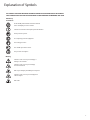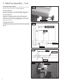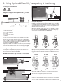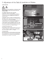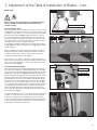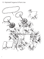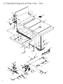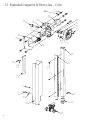
1
Original Instruction Manual
BS400 Premium
16" Bandsaw
Version 3.0
January 2013
To register this product please visit
www.recordpower.info
It is important to register your product as soon as possible in order to receive efficient after sales
support and be entitled to the full 5 year guarantee. Your statutory rights are not affected.
Please see back cover for contact details.
Kg
i
Always wear safety glasses when
using woodworking equipment.
Always read the instructions
provided before using
woodworking equipment.
Kg
Important
For your safety read instructions carefully
before assembling or using this product.
Save this manual for future reference.
1
Contents
Terms & Conditions of Usage
Explanation of Symbols
General Health & Safety Guidance
Additional Health & Safety for Bandsaws
Record Power Guarantee
User Manual
1.
Getting to Know Your Bandsaw
2.
Machine Specification
3.
Machine Assembly
4.
Fitting Optional Wheel Kit, Transporting & Positioning
5.
Adjustment of the Table and Installation of Blades
6.
Adjustment of Guides & Further Operations
7.
Operation and Bandsawing Practice
8.
Dust Extraction
9.
Maintenance
10.
Electrical Connection & Wiring Diagram
11.
Troubleshooting
12.
Diagrams and Parts Lists
EU Declaration of Conformity
Consumables & Spares Quick Find
2
Part Number Part Description
BB1331406
BB1336
BB1331206
BB1333403
BB133103
Blades
1/4” x 6TPI Bandsaw Blade
3/8” x 6TPI Bandsaw Blade
1/2” x 6TPI Bandsaw Blade
3/4” x 3TPI Bandsaw Blade
1” x 3TPI Bandsaw Blade
SBS300-127
Table Insert
SBS400-46
SBS400-56
SBS400-58
SBS400-63
Bandwheels
Drive belt Bandwheel tyre
Wheel Bearing
Brush
SBS400-203
SBS400-262
SBS400-263
SBS400-264
SBS400-265
SBS400-266
Upper Blade Guides
Upper Guide Support Block
Upper Blade Guide Support*
Rear Blade Guide Assembly*
Rear Blade Guide Assembly*
Hex Socket Screw M6 x 12*
Hex Socket Screw M8 x 10*
SBS400-160
SBS400-147
SBS400-151
SBS400-148
SBS400-137
SBS400-131
Lower Blade Guides
Left Cover*
Lower Blade Guide Support
Right Cover*
Insert
Bearing 6021
Tapped Bar
* Not shown in parts diagram.
Explanation of Symbols
THE SYMBOLS AND THEIR MEANINGS SHOWN BELOW MAY BE USED THROUGHOUT THIS MANUAL.
PLEASE ENSURE THAT YOU TAKE THE APPROPRIATE ACTION WHEREVER THE WARNINGS ARE USED.
Mandatory
Instructions
i
Read and fully understand the instruction manual
before attempting to use the machine.
Indicates an instruction that requires particular attention
Wear protective eyewear
iii Use respiratory protective equipment
ii
Use hearing protection
Use suitable protective footwear
Use protective work gloves
Warning
Indicates a risk of severe personal injury or
damage to the machine
Indicates a risk of severe personal injury
from electrical shock
Kg
i
Risk of personal
injury from lifting of heavy items
Kg
Kg
Kg
Indicates a risk of severe
i personal injury from
i
airborne objects
Risk of fire
Kg
i
3
General Health & Safety Guidance
Ensure that you carefully read and fully understand the
instructions in this manual before assembly, installation and
use of this product. Keep these instructions in a safe place for
future reference.
•If the machine is suitable to be used on a workbench, ensure that the
workbench is well constructed and capable of withstanding the weight
of the machine. The machine should always be securely fastened to the
workbench with appropriate fixings.
WARNING: for your own safety, do not attempt to operate this machine
until it is completely assembled and installed according to
these instructions.
•Where possible, floor standing machines should always be secured to the
floor with fixings appropriate to the structure of the floor.
WARNING: When using any machine, basic safety precautions should
always be followed to reduce the risk of fire, electric shock and
personal injury.
Safe Operation
1. Use Personal Protective Equipment (PPE)
•The operation of any machine can result in foreign objects being thrown
into your eyes, which can result in severe eye damage. Protective
eyewear or other suitable eye protection or face shield should be used at
all times. Everyday spectacles only have impact resistant lenses. They are
not protective eyewear and do not give additional lateral protection.
•Use respiratory protective equipment (dust mask etc.) if the machining
operation creates dust. Exposure to high levels of dust created by
machining hardwoods, softwoods and man made composite boards can
result in serious health problems. Some imported hardwoods give off
highly irritating dust, which can cause a burning sensation. The use of
respiratory protective equipment should not be seen as an alternative to
controlling the risk of exposure at source by using adequate dust
extraction equipment.
•The use of ear plugs or ear defenders is recommended when the machine
is in use, particularly if the noise level exceeds 85 dB.
•Wear suitable protective gloves when handling cutting tools or blades.
Gloves should NOT be worn when using the machine as they can be
caught in moving parts of the machine.
•Non-slip safety footwear is recommended when using the machine and
handling large work pieces.
2. Dress appropriately
•Do not wear loose clothing, neckties or jewellery; they can be caught in
moving parts of the machine.
• Roll up long sleeves above the elbow.
• Wear protective hair covering to contain long hair.
3. Safety warnings
• Find and read any warning labels on the machine.
•It is important that any labels bearing health and safety warnings are
not removed, defaced or covered. Replacement labels can be obtained by
contacting our Customer Service Department.
4. Familiarise yourself with the machine
•If you are not thoroughly familiar with the operation of this machine,
obtain advice from your supervisor, instructor, or other qualified person or
contact your retailer for information on training courses. Do not use this
machine until adequate training has been undertaken.
5. Take care when moving or positioning the machine
•Some machines can be very heavy. Ensure the floor of the area in which
the machine is to be used is capable of supporting the machine.
•The machine and its various components can be heavy.
Always adopt a safe lifting technique and seek assistance when lifting
heavy components. In some cases it may be necessary to use mechanical
handling equipment to position the machine within the work area.
•Some machines have optional wheel kits available to allow them to be
manoeuvred around the workshop as required. Care should be taken to
install these according to the instructions provided.
•Due to the nature of the design of some machines the centre of gravity
will be high making them unstable when moved. Extreme care should be
taken when moving any machine.
6. The machine should be level and stable at all times
•When using a leg stand or cabinet base that is designed to be fitted to
the machine, always ensure that it is securely fastened to the machine
using the fixings provided.
4
•The floor surface should be sound and level. All of the feet of the
machine should make contact with the floor surface. If they do not, either
re-locate the machine to a more suitable position or use packing shims
between the feet and the floor surface to ensure the machine is stable.
7. Remove adjusting keys and wrenches
•Ensure that all adjusting wrenches and keys are removed before
switching the machine ‘ON’. There is a risk of severe personal injury or
damage to the machine from airborne objects.
8. Before switching the machine ‘ON’
• Clear the machine table of all objects (tools, scrap pieces etc.)
•Make sure there is no debris between the work piece and the
table / work support.
•Ensure that the work piece is not pressed against, or touching the saw
blade or cutting tool.
•Check all clamps, work holding devices and fences to ensure that they
are secure and cannot move during machining operations.
•Plan the way that you will hold and feed the work piece for the entire
machining operation.
9. Whilst machining
•Before starting work, watch the machine while it runs. If it makes
an unfamiliar noise or vibrates excessively, switch the machine ‘OFF’
immediately and disconnect it from the power supply. Do not restart until
finding and correcting the source of the problem.
10. Keep the work area clear
•Working clearances can be thought of as the distances between
machines and obstacles that allow safe operation of every machine
without limitation. Consider existing and anticipated machine needs,
size of material to be processed through each machine and space for
auxiliary stands and/or work tables. Also consider the relative position of
each machine to one another for efficient material handling. Be sure to
allow yourself sufficient room to safely operate your machines in any
foreseeable operation.
•Cluttered work areas and benches create the risk of accidents. Keep
benches clear and tidy away tools that are not in use.
•Ensure that the floor area is kept clean and clear of any dust and debris
that may create trip or slip hazards.
11. Consider the work area environment
• Do not expose the machine to rain or damp conditions.
•Keep the work area well lit and ensure that there is artificial lighting
available when there is insufficient natural light to effectively light the
work area. Lighting should be bright enough to eliminate shadow and
prevent eye strain.
•Do not use the machine in explosive environments eg. in the presence of
flammable liquids, gases or dust.
•The presence of high levels of dust created by machining wood can
present a risk of fire or explosion. Always use dust extraction equipment
to minimise the risk.
12. Keep other persons away (and pets)
• The machine is designed to be used by one person only.
•Do not let persons, especially children, touch the machine or extension
cable (if used) and keep visitors away from the work area.
•Never leave the machine running unattended. Turn the power supply off
and do not leave the machine unattended until it comes to a
complete stop.
•If the work area is to be left unattended, all machinery should be
switched ‘OFF’ and isolated from the mains power supply.
13. Store machines safely when not in use
•When not in use, machines should be stored in a dry place, out of reach
General Health & Safety Guidance - cont.
of children. Do not allow persons unfamiliar with these instructions or
with the machine to operate it.
14. Do not overreach
•Choose a working position that allows your body to remain balanced
and feed the work piece in to the machine without overreaching.
• Keep proper footing and balance at all times.
15. Electrical supply
•Electrical circuits should be dedicated to each machine or large enough
to handle combined motor amp loads. Power outlets should be located
near each machine so that power or extension cables are not obstructing
high-traffic areas. Observe local electrical guidelines for proper
installation of new lighting, power outlets, or circuits.
• The machine must be connected to an earthed power supply.
•The power supply must be equipped with a circuit breaker that provides
short circuit, overload and earth leakage protection.
•The voltage of the machine must correspond to the voltage of the mains
power supply.
•The mains plug fitted to the machine should always match the power
outlet. Do not modify the plug in any way. If a replacement plug is
required it should be fitted by a competent person and of the correct
type and rating for the machine.
•If you are unsure about any electrical connections always consult a
qualified electrician.
16. Avoid unintentional starting of the machine
•Most machines are fitted with a no-volt release (NVR) switch to prevent
unintentional starting. If in doubt always ensure the machine switch
is in the ‘OFF’ position before connecting it to the power supply. This
means the machine will not automatically start up after a power cut or
switching on of the power supply, unless you first reset the start switch.
17. Outdoor use
• Your machine should not be used outdoors.
18. Extension cables
•Whenever possible, the use of extension cables is not recommended.
If the use of an extension cable is unavoidable, then it should have
a minimum core cross section of 2.5 mm² and limited to a maximum
length of 3 metres.
•Extension cables should be routed away from the direct working area to
prevent a trip hazard.
19. Guard against electric shock
•Avoid body contact with earthed or grounded surfaces such as pipes
and radiators. There is an increased risk of electric shock if your body is
earthed or grounded.
20. Always work within the machine’s intended capacities
•Operator safety and machine performance are seriously adversely
affected if attempts to make the machine perform beyond its limits
are made.
21. Do not abuse the power cable
•Never pull the power cable to disconnect it from the power socket.
Always use the plug.
• Keep the power cable away from heat, oil and sharp edges.
• Do not use the power cable for carrying or moving the machine.
22. Secure the work piece
•Ensure that the work piece is securely held before starting to machine it.
•When working within 300 mm of the machining area, always use a push
stick to feed the work piece in to the blade or cutting tool. The push stick
should have a minimum length of 400 mm. If the push stick becomes
damaged, replace it immediately.
•Use extra supports (roller support stands etc.) for any work pieces large
enough to tip when not held down to the table top.
•Do not use another person as a substitute for a table extension, or as
additional support for a work piece that is longer or wider than the basic
table, or to help feed, support, or pull the work piece.
• Do not attempt to machine more than one work piece at a time.
•When feeding the work piece towards the blade or cutting tool never
position your hands in direct line of the cutting path. Avoid awkward
operations and hand positions where a sudden slip could cause your
hand or fingers to move into the machining area.
23. Stay alert
•Safety is a combination of operator common sense and alertness at all
times when the machine is being used.
•Use all machines with extreme care and do not use the machine when
you are tired or under the influence of drugs, alcohol or medication.
24. Use the correct tool for the job
•Do not use the machine for any purpose other than which it
was designed.
•When selecting replacement cutting tools and blades, always ensure that
they are designed to cut the material that you intend to use them for. If
in any doubt seek further advice from the manufacturer.
25. Connect dust extraction equipment
•Always use dust extraction equipment. The dust extractor should be of
suitable size and capacity for the machine that it is connected to and
have a filtration level appropriate to the type of waste being collected.
Refer to the relevant section of the manual for details of the specific dust
extraction requirements for this machine.
•The dust extractor should be switched ‘ON’ before starting the machine
that it is connected to. The dust extractor should be left running for 30
seconds after the last machining operation is complete in order to clear
any residual waste from the machine.
26. Ensure that the machine is correctly guarded
•Never use the machine if any of the standard safety guards and
equipment are removed or damaged.
•Some machines incorporate safety interlocks to prevent the machine
from being used without the guards in place. Never attempt to bypass
or modify the interlocks to allow the machine to be used without the
guards in place.
27. Maintain your machine with care
•This manual gives clear instructions on installation, set up and
operation of the machine and also details any routine and preventative
maintenance that should be performed periodically by the user.
•Remember always to switch off and unplug the machine from the power
supply before carrying out any setting up or maintenance operations.
•Follow any instructions for the maintenance of accessories
and consumables.
•Do not use compressed air to clean the machine. Always use a brush to
dislodge dust in places that are awkward to reach and a dust extractor
to collect the waste.
•Inspect electric cables periodically and, if damaged, have them replaced
by an authorised service facility or qualified electrician.
•Inspect extension cables (if used) periodically and replace if damaged.
28. Keep cutting tools sharp and clean
•Correctly maintained cutting tools are easier to control and less likely
to bind.
•Cutting tools and blades can become hot during use. Take extreme care
when handling them and always allow them to cool before changing,
adjusting or sharpening them.
29. Disconnect the machine from the power supply
•When not in use, before servicing, changing blades etc. always
disconnect the machine from the power supply.
30. Check for damaged parts
•Before each use of the machine, it should be carefully checked to
determine that it will operate properly and perform its
intended function.
•Check for alignment of moving parts, binding of moving parts, breakage
of parts and any other conditions that may affect the operation of
the machine.
•A guard or other part that is damaged should be properly repaired
or replaced by a qualified person unless otherwise indicated in this
instruction manual.
5
General Health & Safety Guidance - cont.
•Do not use the machine if the switch does not turn the machine ‘ON’
and ‘OFF’.
• Have defective switches replaced by a qualified person.
31. Warning!
•The use of any accessory or attachment, other than those recommended
in this instruction manual, or recommended by our Company may present
a risk of personal injury or damage to the machine and invalidation of the
warranty.
appropriate to its type when used in accordance with these instructions
and with all of the standard safety guards and equipment in place. Only
qualified persons using original spare parts should carry out repairs.
Failure to do this may result in considerable danger to the user and
invalidation of warranty.
33. Caution! Motor may become hot during use
• It is normal for motors on some machines to become hot to the touch
during use. Avoid touching the motor directly when in use.
32. Have your machine repaired by a qualified person
•This machine complies with the relevant safety rules and standards
Additional Health & Safety for Bandsaws
Safe Operation
1. Familiarise yourself with the machine
• Machining operations using bandsaws have a history of serious accidents.
Most result from contact with the moving blade while presenting material
to the blade or moving it from the table. Other minor accidents can occur
whilst setting, cleaning, adjusting or maintaining the machine.
• The machine is designed for cutting wood and composite board (plywood,
MDF etc.). Certain plastics can also be cut using a suitable blade.
2. Before switching the machine ‘ON’
• Ensure that the blade is correctly tensioned and aligned on the
bandwheels and the blade guides are correctly adjusted.
• Ensure that the teeth of the blade are pointing downwards.
• Check the condition of the blade to ensure that no teeth are missing,
damaged or deformed and the blade is not cracked or split. If any of
these conditions apply, replace the blade immediately.
• Ensure that the saw blade type and width are suitable for the material to
be cut.
• Check that the blade width is within the minimum and maximum
permitted on the machine and that the thickness of the blade is suitable
for the diameter of the wheel.
• Some machines have more than one cutting speed. For most wood
cutting applications the faster of the speeds should be used.
• Check the condition of the table insert. Replace it immediately if it is
damaged or showing signs of wear.
• Adjust the guard as close as possible to the work piece being cut.
• Check that access doors are fully closed and that the latches are secure.
6
3. Whilst machining
• Never apply sideways pressure to the blade as this may cause the blade
to break.
• Care must be taken when cutting wood with knots, nails or cracks in
it and / or dirt on it, as these can cause the blade to get stuck. If this
happens, switch the machine ‘OFF’ immediately and follow the procedure
detailed in the manual to remove the blade from the work piece.
•If cutting cylindrical timber use a suitable jig to prevent twisting of the
work piece.
4. This machine falls under the scope of the ‘Health & Safety at Work etc.
Act 1974’, and the ‘Provision & Use of Work Equipment Regulations 1998’.
In addition the elimination or control of risks from wood dust is included in
the above regulations and the ‘Control of Substances Hazardous to Health
(COSHH) Regulations 2002’. We recommend that you study and follow
these regulations.
Further guidance can be found in the ‘Safety in the use of narrow
bandsaws – Woodworking sheet No. 31’ and the ‘Safe use of woodworking
machinery’ code of practice booklet (L114) published by Health & Safety
Executive and available from their website www.hse.gov.uk.
Record Power Guarantee
“Products” means the Products sold by Record Power subject to these
terms and conditions;
“Record Power” is Record Power Limited, whose company registration
number is 4804158 and registered office address is Centenary House, 11
Midland Way, Barlborough Links, Chesterfield, Derbyshire S43 4XA and sells
through a network of Authorised Dealers;
“Authorised Distributor” is the nominated importer for your region
who will generally sell through a network of Authorised Dealers. Details of
Authorised Distributors for specific countries can be found in the Product
manual or at www.recordpower.info;
“Authorised Dealer” is a retailer or business authorised to sell Record
Power Products to end users.
Guarantee
1
1.1 Record Power guarantees that for a period of 5 years from the date
of purchase the components of qualifying Products (see clauses 1.2.1
to 1.2.9) will be free from defects caused by faulty construction
or manufacture.
1.2 During this period Record Power, its Authorised Distributor or
Authorised Dealer will repair or replace free of charge any parts
which are proved to be faulty in accordance with paragraphs 1.1
above provided that:
1.2.1 you follow the claims procedure set out in clause 2 below;
1.2.2 Record Power, our Authorised Distributor or Authorised Dealer are
given a reasonable opportunity after receiving notice of the claim to
examine the Product;
1.2.3if asked to do so by Record Power, its Authorised Distributor or
Authorised Dealer, you return the Product, at your own cost, to
Record Power’s premises or other approved premises such as those
of the Authorised Distributor or supplying Authorised Dealer, for the
examination to take place;
1.2.4the fault in question is not caused by industrial use, accidental
damage, fair wear and tear, wilful damage, neglect, incorrect
electrical connection, abnormal working conditions, failure to follow
our instructions, misuse, or alteration or repair of the Product without
our approval;
1.2.5the Product has been used in a domestic environment only;
1.2.6 the fault does not relate to consumable Products such as blades,
bearings, drive belts or other wearing parts which can reasonably
be expected to wear at different rates depending on usage (for full
details contact Record Power or your local Authorised Distributor);
2
Claims Procedure
2.1 In the first instance please contact the Authorised Dealer who
supplied the Product to you. In our experience many initial problems
with machines that are thought to be due to faulty parts are actually
solved by correct setting up or adjustment of the machines. A good
Authorised Dealer should be able to resolve the majority of these
issues much more quickly than processing a claim under
the guarantee.
2.2 Any damage to the Product resulting in a potential claim under the
guarantee must be reported to the Authorised Dealer from which it
was purchased within 48 hours of receipt.
2.3If the Authorised Dealer who supplied the Product to you has been
unable to satisfy your query, any claim made under this Guarantee
should be made directly to Record Power or its Authorised Distributor
(for details of the Authorised Distributor in your country please see
your Product manual or check www.recordpower.info for details).
The claim itself should be made in a letter setting out the date and
place of purchase, and giving a brief explanation of the problem
which has led to the claim. This letter should then be sent with
proof of the purchase date (preferably a receipt) to Record Power or
its Authorised Distributor. If you include a phone number or email
address this will help to speed up your claim.
2.4Please note that it is essential that the letter of claim reaches Record
Power or its Authorised Distributor on the last day of this Guarantee
at the latest. Late claims will not be considered.
Limitation of Liability
3
3.1 We only supply Products for domestic and private use. You agree not
to use the Product for any commercial, business or re-sale purposes
and we have no liability to you for any loss of profit, loss of business,
business interruption or loss of business opportunity.
3.2This Guarantee does not confer any rights other than those expressly
set out above and does not cover any claims for consequential loss
or damage. This Guarantee is offered as an extra benefit and does
not affect your statutory rights as a consumer.
Notice
4
This Guarantee applies to all Products purchased from an Authorised
Dealer of Record Power within the United Kingdom of Great
Britain and Northern Ireland. Terms of Guarantee may vary in other
countries – please check with the Authorised Distributor in your
country (details of the Authorised Distributor for your country can be
found in the manual or at www.recordpower.info).
1.2.7the Product has not been used for hire purposes, by you or by a
previous owner;
1.2.8 the Product has been purchased by you as the guarantee is not
transferable from a private sale.
1.2.9where the Product has been purchased from a retailer, the 5 year
guarantee is transferable and begins on the date of the first purchase
of the Product and in the event of a claim under this guarantee
proof of the original purchase date will be required to validate the
warranty period.
7
1. Getting to Know Your Bandsaw
A
J
H
B
C
K
O
G
D
E
N
F
M
L
A. Lifting Ring
B. Tension Indicator Window
C. Blade Tension Wheel
D. Switch Unit
E. Rip Fence Assembly
F. Belt Tension & Speed Change
Handwheel
G. Blade Guide
2. Machine Specification
Maximum depth of cut:
Throat width:
Blade length:
Blade width:
Blade tilt:
Table size:
Saw blade speed:
Motor:
Full load current:
Noise Emission:
8
305 mm
416 mm
3378 mm
6 - 25 mm
-10º to 45º
535 x 485 mm
480 & 820 M/min
230 V / 50 Hz / 2 hp / 1500 W
8.4 A
Sound power level < 85dB (A)
Sound pressure level < 85dB (A)
H. Rise & Fall Hand wheel
J. Blade Tension Cam Handle
K. Rise & Fall Lock Knob
L. Extraction Port
M. Motor
N. Table Tilting Knob
O. Blade Tracking Knob
3. Machine Assembly
Fig. 3.1
Kg
Kg
CAUTION!
i suitable lifting
The machine is heavy. Additional help or a
device or support will be required for placing the machine
in the workshop.
i
3.1 Unpacking and components included
The machine is supplied partly assembled.
When unpacking the machine the following components are included
for the initial assembly Fig. 3.1:
1. 1 Large crank handle
2. 1 Small crank handle
3. Table stop screw and nut
4. 1 Lifting ring
5. 4 Table bolts, washers and spring washers
6. Tool kit
7. BS400 Bandsaw
8. Fence bar and scale
9. Extraction hose
10. Rise and fall hand wheel
11. Mitre fence
12.2x jubilee clips
13.Fence assembly
14.Belt tensioner hand wheel
15. Table
16. Fence
1
2
3
4
5
7
6
8
9
10
12
13
11
3.2 Rise & fall handle
Attach the rise and fall hand wheel to the rise and fall shaft and
tighten the socket head bolt with a 5 mm hex key. Then attach the
handle and tighten with a 10 mm wrench. See Fig. 3.2.
3.3 Belt tensioner handle
Attach the belt tension hand wheel to the tension shaft and tighten
the socket head bolt with a 5 mm hex key. Then attach the handle and
tighten with a 10 mm wrench. See Fig. 3.3.
Fig. 3.2
Rise & fall
15
Fig. 3.3
14
16
Belt tension & speed change
9
3. Machine Assembly - Cont.
Fig. 3.4
Trunnion
Note: When assembling this Bandsaw, DO NOT fully tighten the
nuts and bolts until the assembly is complete.
3.4 Fitting the table
i - 13 mm wrench
Tools Required:
With the help of another person, lift the working table onto the trunnion.
Mount the working table on the trunnion using the supplied 4 x hex bolts
and 4 x washers See Fig. 3.4.
3.4 Fitting the fence bar
Attach the fence bar to the table as shown in Fig. 3.5, ensuring 2 washer
are placed next to the fixing nuts. Use the 2 remaining nuts and washer to
secure the fence bar from the underside of the table, Fig. 3.6. Do not fully
tighten yet as adjustment may be necessary.
3.5 Fitting the fence scale
Place fence scale onto the table, Fig. 3.7 and fix with the two hex
socket screws.
Hexagon screw & washer
Fig. 3.5
Fixing nuts
& washers
Fence bar
Fig. 3.6
Fig. 3.7
Fixing nuts &
washers
Hex socket screw
10
3. Machine Assembly - Cont.
3.6 Assembling the mitre fence
1. Unscrew the locking nuts from the mitre fence Fig. 3.8.
Fig. 3.8
Mitre fence
2. Place the protractor with the flat edge running parallel to the mitre fence.
3. Position it in such a way that the fence screws slot into the holes on the
protractor Fig. 3.9.
Fence screws
4. Replace and re-tighten the locking nuts.
5. Position the slide underneath the protractor so that the threaded bar sits
in the angle slide and the pivot pin inserts into the pivot hole Fig. 3.10 and
Fig. 3.11.
Locking nuts
6. Tighten the ratchet handle onto the threaded bar Fig. 3.11.
Fig. 3.9
Protractor
Fig. 3.10
Slide
Angle slide
Threaded bar
Pivot pin
Ratchet handle
Fig. 3.11
Ratchet handle
11
3. Machine Assembly - Cont.
3.7 Fitting the fence assembly
Place the fence assembly onto the fence bar. Position the fence on to the
table and lock in place using fence Locking knob, Fig. 3.12.
Fig. 3.12
3.8 Fence alignment 1
Align the fence assembly in or out until parallel with the side of the mitre
guide slot by adjusting the fence bar nuts accordingly, see Fig. 3.13.
3.9 Fence alignment 2
Check that the fence is 90º to the table using a suitable square. If no
adjustment is needed fully tighten the fence bar nuts. If adjustment is
required this is achieved by raising or lowering either side of the fence rail
until the fence itself is 90º to the table, Fig. 3.14. Once set at 90º, fully
tighten the fence bar nuts.
3.10 Dust Extraction Hose
To install the dust extraction hose, attach it to the outlet near the top of the
lower band wheel box and the inlet at the rear of the base of the bandsaw,
Fig. 3.15.
Locking knob
Fig. 3.13
Mitre guide slot
Fence
Adjustment
Fence bar
Fig. 3.14
Fence
Adjustment
Fence bar
Fig. 3.15
Jubilee clips
Hose
12
4. Fitting Optional Wheel Kit, Transporting & Positioning
4.1 Fitting the optional wheel kit
Fig. 4.4
Kg
Kg
CAUTION! The machine is heavy. Additional help or a suitable
i fitting wheels.
lifting device or support will be required for
Fig. 4.1
i
1
Jockey bar
4
Hexagon bolts & split pin
2
6
5
3
4.3 Moving the machine
Damage caused by incorrect handling, transportation or installation may
invalidate the guarantee. Consequently if in doubt about the safe handling
or installation of the machine obtain the services of a competent technician,
contact Record Power customer services, or contact the organisation from
which the machine was purchased.
When transporting this machine do not strap across the table or over the
top of the machines, Fig 4.5a and 4.5b. Always locate retaining straps
over the lower wheel box beneath the table Fig. 4.5c.
Contents of the packages
1. Jockey support bracket
2. Axle
3. 4 x split pins and washer
4. 4 x wheels
5. 2 x nuts, bolts and washers
6. Jockey bar
Fig. 4.5a
Fig. 4.5b
Fig. 4.5c
The jockey support bracket is held in place by 2 bolts. The jockey support
bracket also levels the machine after the rear wheels have been fitted.
• First lift up the front (table end) of the machine with a suitable lifting
device. Do not lift the machine using the table. Now fit the jockey support
bracket to the base, bolt the bracket through the pre-drilled hole at either
end of the base and fully tighten, Fig.4.2.
• Again using a suitable support, lift the rear (spine end) of the machine up
and slide the axle through the base. Fit a wheel to either end of the axle and
secure them with a washer each side of the wheel and split pin, Fig.4.3.
4.2 Using The Jacking Bar
The wheel kit is now fitted. Attach the wheels to the jockey bar using
the hexagon bolts and split pin, this jacking bar is now used to lift and
manoeuvre the front of the machine, Fig.4.4.
CAUTION! This wheel kit is only to be used on a level surface.
When moving and positioning this machine do not hold the table and drag
it, always hold the spine or lower wheel box, see Fig 4.6a and 4.6b. If
moving long distances position the machine on a trolley before moving, see
Fig 4.6c.
Fig. 4.6a
Fig. 4.6b
Fig. 4.6c
Fig. 4.2
Bolt
Jockey support bracket
Fig. 4.3
Washers & split pin
4.4 Positioning the machine
The machine should not be located in a confined space. Ensure that the
working area is adequately lit. A cabinet located nearby is useful for the
safe and secure storage of tooIs, blades and accessories.
The machine should be located on a solid surface that is level. If the
machine is to be permanently located four mounting holes are provided in
the base so the machine can be bolted to the floor. Ensure that the anticorrosive coating is removed from the table and other working parts used
before use.
13
5. Adjustment of the Table & Installation of Blades
SETTING THE TABLE
CAUTION!
Before carrying out any adjustments or maintenance ensure
that the machine is isolated and disconnected from the
electricity supply.
i
i
5.1 Setting the table stop at 90º to saw blade
Tools Required:- Small 90º square (Not supplied)
The table can be set at 90º to the Bandsaw Blade see Fig. 5.1 by
adjusting the table stop screw see Fig. 5.2 underneath the table.
• First offer the square up to the blade to give an indication of
adjustment required.
• If the table is not at 90º to the blade use table tilting mechanism
see Fig. 5.3 to adjust the table until it is 90º to the blade. If the table
stop screw position is too high it may be necessary to wind this down
out of the way so 90º can be achieved see Fig. 5.2.
• Once the table is at 90º to the blade lock off the lock handle on the
table tilt mechanism to secure the table position see Fig. 5.3.
• Now set the table stop screw see Fig. 5.2, the table stop screw
should be adjusted so that the head of the screw makes contact with
the top surface of the lower bandwheel housing. Once the stop screw
is set to the correct length, it is secured by tightening the lock nut up
to the flat registration point on the underside of the table.
Kg
Fig. 5.1
Kg
5.2 Adjusting the table tilt scale
Once the table is set at 90º to the Bandsaw Blade it may be necessary
to adjust the angle pointer on the angle scale so any further angles
are accurate. To do this use a Phillips screwdriver to loosen the pan
head screw and adjust the pointer to 0º, see Fig. 5.3.
Fig. 5.2
Flat registration point
Table stop screw
Fig. 5.3
5.3 Tilting the table
The tilt mechanism will be used when squaring the table to the blade.
Tilt the table as follows: Loosen the lock handle on the table trunnion.
Turn the table tilting knob to adjust the table angle see Fig. 5.3. Use
the angle indicator scale on the trunnion bracket to find the desired
angle. Re-tighten the lock handle to secure the table.
Lock handle
Angle pointer
14
Tilting knob
5. Adjustment of the Table & Installation of Blades - Cont.
BLADE SETUP
Kg
CAUTION!
Before carrying out any adjustments or maintenance ensure
that the machine is isolated and disconnected from the
electricity supply.
i
i
5.4 Tensioning the blade
The blade tensioning wheel should be used to increase or decrease tension
see Fig. 5.4. The only truly accurate way to check a blade is with a tension
meter. These are very expensive so most users may need another method.
The blade tension indicator, Fig. 5.4 should be used first, as a guide to
the correct tension. We then suggest testing the tension by the amount
the blade will deflect sideways. First set the guides to 6 inches above the
table, making sure the saw is turned off push the blade sideways with a
reasonable amount of pressure using the push stick.
A correctly tensioned blade should not move more than a 1/4” sideways,
see Fig. 5.5, A. If the blade is over-tightened, as in Fig. 5.5 B, the blade
could be damaged.
Fig. 5.4
Kg
Blade tensioning wheel
Blade tension indicator
Fig. 5.5
A
B
3
7
However perhaps the most tried and tested way of blade tensioning is
simply: If the bandsaw is cutting accurately then the blade is tensioned
correctly, if the blade tends to wander and an accurate cut cannot be
achieved then the blade tension needs adjusting.
If the machine is to stand idle for a period it is good practice to slacken
tension and re-tension when next using. On the BS400 the simplest way to
release and re-tension the blade is to use the cam handle located on the
back on the machine. Fig. 5.6.
5.5 Tracking the Bandsaw blade
Isolate the machine from the supply by unplugging the mains plug. Set
the tracking of the blade before setting the blade guides. Once the blade
is tensioned, track the blade by turning the upper bandwheel by hand and
adjusting the tracking knob see Fig. 5.6. When viewed from back of the
machine turning the tracking knob clockwise the blade will move towards
the back of the bandwheel, by turning the tracking knob anti-clockwise
the blade will move to the front of the bandwheel. The blade should run
as close to the centre of the bandwheel as possible, as shown see Fig.
5.7. On 1/4”, 3/8” and 1/2” blades it may be necessary to run the blade
to rear of the bandwheel. After the blade is tracked in the desired position
on the bandwheel, rotate the band wheel several more times by hand
without any further adjustment ensuring that the blade remains in the
same position. Once this has been achieved lock the tracking knob with
the winged nut see Fig. 5.6.
The machine should then be run for a few seconds before any adjustment
of guides are carried out. It takes a few revolutions of the band wheel
for the effect of adjustment on the tracking knob to become apparent.
To avoid over adjusting, make small gradual adjustments on the tracking
knob and revolve the band wheel a few times to check the alignment of
the blade before making further adjustments.
Fig. 5.6
Winged nut
Cam Handle
Tracking knob
Fig. 5.7
15
6. Adjustment of Guides & Further Operations
Fig. 6.2
Thrust bearing
CAUTION!
Before carrying out any adjustments or maintenance ensure
that the machine is isolated and disconnected from the
electricity supply.
i
i
6.1 Adjusting the Upper Guides
To adjust the upper blade guides, first position the guide assembly relative
to the blade, by slackening off the hex screw - A Fig. 6.1 and moving the
guide carrier until the roller guides are just behind the gullets of the blade
see Fig. 6.3. Next set the roller guides as near as possible to the blade
without actually touching. This is done by unlocking the locking the nut
on each side of the guide adjustment see Fig. 6.1. Do not let the roller
guides actually touch the blade as this will adversely affect the life of the
blade. Finally adjust the thrust bearing to be just clear of the back of the
blade see Fig. 6.4.
Do this by unlocking the hex socket screw B Fig. 6.2. When the correct
adjustment is reached, lock the thrust bearing in position with hex socket
screw B Fig. 6.1.
Kg
Kg
Fig. 6.3
B
Fig. 6.5
C
B
Fig. 6.4
A
Roller guide
Thrust bearing
Fig. 6.6
Blade gullet
6.2 Adjusting Lower Guides
To adjust the lower blade guides, first slacken off the hex socket screw - A
see Fig. 6.5, move the guide carrier casting so the guides are just behind
the gullets of the blade. Next set the roller guides as near as possible to
the blade without actually touching. This is done by releasing the hex head
socket screw - B see Fig. 6.5 on each side of the blade. Finally adjust the
rear thrust bearing to be just clear of the back of the blade see Fig. 6.6.
To do this first unlock the Hex socket screw - C see Fig. 6.5 then using the
adjustment knob at the rear, position the thrust bearing Fig. 6.7.
Fig. 6.7
6.3 Adjusting the cutting height
Once the blade is set, the cutting height must be adjusted so there
is maximum guarding for the blade and so that the blade guides are
providing optimum support to the blade. To adjust the cutting height
loosen the rise and fall lock knob and turn the rise and fall handwheel to
raise or lower the guide post/upper blade guide assembly to the desired
height Fig. 6.8. The upper blade guide should provide approximately 5
mm clearance above the workpiece. After the desired position has been set
tighten the guide post lock knob. Always check the guide bearing for slight
adjustment when the height of cut is changed.
Fig. 6.1
A
Adjustment knob
Fig. 6.8
Lock knob
Guide carrier
Locking nut
Rise & fall handwheel
Roller guides
16
Guide adjustment
6. Adjustment of Guides & Further Operations - cont.
Fig. 6.9
Kg
CAUTION!
Before carrying out any adjustments or maintenance ensure
that the machine is isolated and disconnected from the
electricity supply.
i
i
6.4 Adjusting the drive belt tension
Use the crank handle, Fig. 6.9 to adjust the tension of the drive belt.
Rotate the handle anti-clockwise to increase the tension and clockwise
to decrease tension. As a guide the belt is adequately tensioned when
using the index finger to impart reasonable pressure on the belt - the belt
should not deflect more than 1/4”. But like tensioning a bandsaw blade,
this is very subjective and the best test is in operation, if the belt isn’t
slipping or wearing excessively then the drive belt is tensioned correctly.
Kg
6.5 Changing the Blade Speed
The BS400 has two blade speeds 820 m/min for wood and 480 m/min for
some plastics and acrylics. This machine is not suitable for cutting metals.
Crank handle
Fig. 6.10
The lower bandwheel has two integral multi vee form pulleys and the
motor shaft has a twin multi vee form pulley.
The vee belt passes around the bandwheel pulley, the motor pulley and
the plain tension roller. The belt tension is released and applied by using
the crank handle, this moves the tension roller and allows the speed to be
changed, see Fig. 6.9.
High Speed 820 m/min
Before changing the speed always make sure the machine has been
isolated from the mains supply.
For the high speed the belt should be fitted to the rear pulley on both the
motor and bandwheel, Fig. 6.10.
Fig. 6.11
Lower Speed 480 m/min
Before changing the speed always make sure the machine has been
isolated from the mains supply.
For the low speed the belt should be fitted to the front pulley on both the
motor and bandwheel, Fig. 6.11.
After any adjustment of the belt ensure the poly vees are correctly
located in the vee slots as failure to do so could damaged the belt
in use.
i
17
7. Operation and Bandsawing Practice
Basic Bandsawing Principles
• The blade cuts on a continuous down stroke.
• Slowly feed the workpiece towards the blade, using only light pressure
whilst letting the blade do the cutting. Always use a push stick and take
care.
• Firmly hold the workpiece and feed it towards the blade slowly, using the
push stick and keeping your hands well away from the blade.
• For best results the blade must be sharp. Damaged or worn blades should
always be replaced.
• Select the correct blade for the job, depending on the thickness of the
wood and the cut to be made (see blade selection).
• For straight cutting use the rip fence supplied.
• When cutting shapes, follow the design marked out by pushing and
turning the workpiece evenly. Do not attempt to turn the workpiece
without pushing it, as this may cause the workpiece to get stuck, or the
blade to bend.
CAUTION! Particular care should be taken towards the end of the cut as
there will be a sudden decrease in resistance and care must be taken to
stop hands from being thrown towards the blade. Always use a push stick.
i
Kg
Restarting
In the Event of a Blockage or if the Machine Stalls
If the bandsaw stalls due to the blade becoming trapped in the work piece,
switch it off immediately by pressing the emergency stop button and wait
for the machine to come to a complete stop before proceeding further.
If the blade is trapped within the work piece, it may be necessary to prize
the work piece apart slightly using a suitable lever in order to free the
blade. If it is not possible to free the blade using this method, then it may
be necessary to cut the blade using suitable side cutters or tin snips.
Replace the blade if necessary and ensure that it is correctly tracked and
tensioned and that both doors of the bandsaw are fully closed and secured
before attempting to re-start the machine.
To re-start the machine, press the green button marked ‘I’ on the switch.
In the Event of a Power Failure
The bandsaw is fitted with a no volt release (NVR) switch to protect the
user against automatic starting of the machine when power is restored
after a power failure.
In the event of a power failure, first locate and rectify the source of the
failure. If the fault is within the power circuit of the workshop, there may
be an underlying cause (circuit overload etc.) that should be investigated
by a qualified electrician, before attempting to restore the power source.
If a cutting operation was taking place when the power supply was
interrupted, then it may be necessary to free the blade from the work piece
before attempting to re-start the machine.
Once the power is restored, the machine can be re-started by pressing the
green button marked ‘I’ on the switch.
Always ensure that your machine is properly maintained and clean. Before
commencing work on an important project, it is advisable to familiarise
yourself with the operation of the equipment by practising on low value or
scrap materials.
Blade Selection (TPI)
Complicated Cutting
• Correct blade choice is primarily dependant on two factors: material
thickness and material type.
Very complicated cuts and small radius curves are the best accomplished
with the aid of pre-drilled holes combined with a few tangential or radial
cuts. This technique will achieve excellent results without putting undue
tension on the blade and blade guide assembly.
The selection of the best blade configuration (see the table below) is
necessary for optimum cutting performance.
• Greater TPI should be selected as material thickness decreases.
• However, if the TPI is too great, the tooth loading will be insufficient
to enable penetration; and cutting. The teeth will also rapidly lose their
sharpness.
• For thicker material a lower TPI should be used otherwise the gullet will
not be sufficient to clear the waste and the blade will stall or burn the
wood.
WARNING! In circumstances such as cutting deep or wet timber,
the work piece may close up behind the blade causing it to stall. In
the event that the blade stalls whilst cutting, ease the work piece
backwards slightly, to release
feed pressure from the blade. Allow the
i
blade to reach full speed before continuing to feed the work piece in
to the blade. If the blade fails to move when feed pressure is released,
immediately switch off the machine and disconnect the power supply
before attempting to free the blade from the work piece.
Kg
WARNING! If any component of the machine fails whilst in use or
if the blade should break whilst the machine is running, immediately
switch off the machine and disconnect from the power supply. Remove
i replace only with genuine Record Power
the faulty component and
replacement parts. Any electrical components should only be replaced
by a suitably qualified person. To replace a broken blade, please refer
to the section of this manual entitled “Band saw Blade Set Up”.
Always remember to fully release the blade tension mechanism before
attempting to fit a new blade. If you are in any doubt about using the
machine following a failure or if you need to order replacement spare
parts or blades, please contact customer services in your country.
Kg
18
• In general a minimum of 3 teeth should be in contact with the wood at all times during cutting.
The accompanying blade selection chart (see the table opposite) gives
guidance on the TPI that should give the best results when cutting a variety
of material types and thickness. The table below provides recommendations
on selecting the correct blade for a variety of commonly used materials. If
in doubt about any aspects of blade selection contact Customer Services in
your country.
The table provides a guide to selection only. Exact tooth configurations
are not always available, nor are all blade configurations covered, but the
principles remain the same. For special applications, custom blades can be
supplied please call Customer Services in your country and we can advise
you accordingly on your specific needs.
7. Operation and Bandsaw Practice - Cont.
Material
Perspex
Material Thickness
<6 mm
6-12 mm
16 TPI
14 TPI
12-25 mm
-
Chipboard
-
6 TPI
3-6 TPI
Fibre board
16 TPI
14 TPI
-
Hardboard
10 TPI
-
-
Plywood
10 TPI
8 TPI
6 TPI
>25mm
3-4 TPI
3-4 TPI
Strawboard
14 TPI
10 TPI
-
Cork
14 TPI
6 TPI
3 TPI Leather
14 TPI
-
-
-
Rubber
10 TPI
8 TPI
-
-
Wood -log
-
-
-
3-4 TPI
Wood -soft 6 TPI
3-6 TPI
3-4 TPI
3-4 TPI
Wood -hard
6 TPI
3-6 TPI
3-4 TPI
3-4 TPI
Wood -wet
-
-
-
3-4 TPI
Blade Selection (TPI) - Cont.
Having selected an appropriate blade for the particular thickness and type
of material to be sawn, it is essential that the saw blade is allowed to cut
freely by not applying too much pressure.
• The need for excessive pressure is likely to be a result of the incorrect
blade selection or a worn blade and will result in inaccurate cutting and
possibly blade breakage.
3-4 TPI
Blade Selection (Width)
• When cutting shapes, the width of the blade limits the minimum radius
that can be cut.
• If the blade is too wide for the cutting radius the blade will twist and
possibly jam or break.
• The smaller the radius the narrower the blade has to be.
The diagram below provides guidance on the minimum radius to be cut
with the most commonly used blade widths.
Blade width: 1/2”
Min radius: 31/4”
Blade width: 3/8”
Min radius: 21/2”
Blade width: 1/4”
Min radius: 11/16”
19
7. Operation and Bandsaw Practice - Cont.
Blade Selection Summary
Narrow Blade
Wide Blade
To see how TPI and width of the blade come
together, use the table opposite for reference.
• Regularly examine the blade for excessive
damage or cracking as a result of fatigue. If
such damage is present replace the blade.
Application
Coarse
Blade
The following range of blades are available for
the BS400:
BB1331406
BB1336
BB1331206
BB1333403
BB133103
BB133 - 3 PACK
20
1/4” x 6 TPI Blade
3/8” x 6 TPI Blade
1/2” x 6 TPI Blade
3/4” x 3 TPI Blade
1” x 3 TPI Blade
1/4 x 6 TPI,
3/8” x 4 TPI,
3/4” x 3 TPI
Fine
Blade
7.9 Record Power BS400 Blade Range
Record Power’s high performance bandsaw
blades are manufactured to the highest quality
tolerances using a specialist premium high carbon
steel strip. The extensive quality control program
which involves digital tooth profile checks, set
analysis, straightness testing, hardness testing
and micro structural analysis results in a blade
that cuts straighter and has harder, longer lasting
teeth. A premium British blade that can last up to
ten times longer than other blades on the market.
Application
TIGHT CONTOUR MEDIUM
CONTOUR
STRAIGHT CUT /
LARGE
CONTOUR
Blade Spec
Blade Spec
Blade Spec
width
widths
widths
1/4”
3/8”
1/2”
teeth
teeth
teeth
4 TPI
4 TPI
4 TPI
Material
Blade Spec
Blade Spec
Blade Spec
General
Timber
width
widths
widths
1/4”
3/8”
1/2”
teeth
teeth
teeth
4 - 6 TPI
4 - 6 TPI
4 - 6 TPI
Material
Blade Spec
Blade Spec
Blade Spec
Thin / Hard
Timber
width
widths
widths
1/4”
3/8”
1/2”
teeth
teeth
teeth
6 TPI
6 TPI
6 TPI
• It is important to use a sharp blade. Dull teeth
result in increased feed pressure producing a
poor quality finish and an inaccurate cut.
Note:
As well as the blades listed, we can also
supply bandsaw blades to almost any
specification iplease contact your preferred
stockist or call customer services in your
country.
Application
Material
Thick / Soft
Timber
7. Operation and Bandsaw Practice - Cont.
Custom Jigs & Work Support
A bandsaw is one of the most versatile machines in the workshop and with careful preparation many problems encountered on a job can be overcome.
By making and using custom jigs repetitive and accurate work can easily be achieved, the following illustrations are some examples of typical jigs and
supports used on a bandsaw.
Ex. 5. Jig for accurate repetitive wedges.
Ex. 2. Always support round pieces with a wedge or vee block. Take extreme
care as there is a danger that if the work is not secured properly the blade will
snatch the work piece, potentially causing it to spin or bounce back at you.
Ex. 6. By mounting a registration pin on a slide repetitive circles
can easily be achieved.
100
Ex. 1. Supporting large workpieces with roller stands or take off tables.
45
º
0
60
25
Ex. 3. Use a side pressure pad for accurate cutting of taller material.
Ex. 7. Angle cutting jig for accurate repetitive compound angles.
40
0
Ex. 4. Chamfered pieces can be cut squarely using an additional support jig
on the opposite side of the work piece to the fence.
180
100
12
20
0
21
8. Dust Extraction
The Importance Of Dust Extraction
DX4000 High Filtration Dust Extractor
Before the machine is started, ensure that adequate dust extraction
provisions have been installed. Dust extraction is extremely important not
only for health and safety but also for the correct upkeep of the machine.
Saw dust can cause the machine not to operate properly or even fail
completely. By keeping the machine free of large amounts of waste the
performance will be optimised. If a large amounts of MDF or toxic woods
are to be cut we recommend that there is a good ventilation system in place
and that in addition to proper extraction a mask or respirator be worn as
minimum protection.
Drum type extractor, 80 litre capacity, Twin 1 kW motor, suitable for heavy
usage ie if one motor is switched off for 20 minutes then the other can
be used thus enabling continuous usage. Or both motors can be used
simultaneously giving maximum suction but in this mode the extractor must
be switched off for 20 minutes every hour. 0.5 micron filtration
Record Power Extractors
Record Power offer a range of high quality dust extractors, we offer both
drum and bag type extractors which filter down 0.5 micron providing
protection from harmful fine dusts. All Record Power dust extractors & chip
collectors have 100 mm inlets and hoses.
DX1000 High Filtration Dust Extractor
Drum type extractor, 45 litre capacity, single 1 kW motor, suitable for
intermittent use ie must be switched off for 20 minutes every hour.
0.5 micron filtration
RSDE1 High Filtration Dust Extractor
DX5000 High Filtration Dust Extractor
Bag type extractor, 200 litre capacity, Twin 1 kW motor, suitable for heavy
usage ie if one motor is switched off for 20 minutes then the other can
be used thus enabling continuous usage. Or both motors can be used
simultaneously giving maximum suction but in this mode the extractor must
be switched off for 20 minutes every hour. 0.5 micron filtration
CX2600 Chip Collector
Large capacity chip collector, with a powerful 0.37 kW induction motor. An
extremely smooth running unit suitable for continuous usage. Very quiet
impeller system extracts dust and chippings.
Suitable for chip collection or finer dust using the optional
filter cartridge
CX3000 Chip Collector
Drum type extractor, 45 litre capacity, single 1 kW motor, suitable for
intermittent use ie must be switched off for 20 minutes every hour.
0.5 micron filtration
Larger capacity chip collector, with a more powerful 0.75 kW induction
motor and heavy duty construction. An extremely smooth running unit
suitable for continuous usage. Very quiet impeller system extracts dust
and chippings.
RSDE2 High Filtration Dust Extractor
Suitable for chip collection or finer dust using the optional
filter cartridge
Drum type extractor, 50 litre capacity, single 1 kW motor, suitable for
intermittent use ie must be switched off for 20 minutes every hour.
0.5 micron filtration
RSDE/2A High Filtration Dust Extractor
with Auto Switching
Drum type extractor, 50 litre capacity, single 1 kW motor, auto switching
allows the machine to be turned on and off as machines and power tools
are operated. Suitable for intermittent use ie must be switched off for 20
minutes every hour. Maximum auto switch capacity 1.1 kW.
0.5 micron filtration
Bandsaws
Circular saws
Sanders
Intermittent usage
DX1000
RSDE1
3
3
Recommended
Recommended
Bandsaws
Circular saws
Sanders
Heavy usage
Planer Thicknessers
Spindle Moulders
Universals
Intermittent usage
Planer Thicknessers
Spindle Moulders
Universals
Heavy usage
Dust Extraction
System
Intermittent usage
22
RSDE2
Air Cleaners
It is strongly advised to also use an air cleaner to remove the fine airborne
dust present in the workshop which cannot be removed using machine
extraction. Record Power offer a range of air cleaners suitable for all home
workshops. Please contact your preferred stockist or call customer services in
your country.
RSDE/2A
DX4000
DX5000
3
3
3
3
Recommended
Recommended
Recommended
Recommended
3
3
Recommended
Recommended
CX2600
CX3000
3
3
3
3
3
3
Recommended
Recommended
Can be used
Recommended
Recommended
Recommended
3
3
3
3
Can be used
Recommended
Recommended
Recommended
3
3
Can be used
Recommended
i
9. Maintenance
Fig. 9.1
Kg
Hex screw
CAUTION!
Before carrying out any adjustments or maintenance ensure that
the machine is isolated and disconnected from the
electricity supply.
i
i
9.1 Replacing the bandsaw blade
Kg
Keep plate
Kg
HAZARD! Take great care when unpacking the bandsaw blade as they are
usually folded and can spring out very suddenly with great force.
TIP: If the new blade being fitted is a different width to the one being
removed, it is advisable to move back and slacken off all blade guides
before fitting the new bladei as this will make fitting easier. Whenever a
different size blade is fitted the blade guides will always need re-setting.
1. Isolate the machine from the power supply.
2.Open the top and bottom bandwheel doors by turning the star handle,
Fig. 9.3 (14).
3.Remove the hex socket screw and keep plate from the underside of the
table, Fig 11.1.
4. Move the cam lever clockwise to release the blade tension.
Fig. 9.3 (17).
5.Remove the bandsaw blade by feeding it through the slot in the table,
upper blade guides & guard and slot in the spine of the machine taking
care not to cut yourself, wear gloves if necessary.
• Fit the new blade ensuring the blade teeth are pointing downwards and
towards you at the position where the blade passes through the table.
• Ensuring that the blade is fully in place on bandwheel. Simply re-apply
tension using the cam handle lever. • Adjust the blade tension further if required using the blade
tension wheel.
6.Check the blade tracking on the newly fitted blade by turning the
upper wheel by hand. The blade should run as close to the centre of
the bandwheel as possible. On 1/4", 3/8" and 1/2" blades it may be
necessary to run the blade to rear of the bandwheel, see section 5.5.
7.If required adjust the tracking using tracking knob (15) and lock knob
to the rear of the upper bandwheel housing. When the tracking is
correct lock the setting, see section 5.5.
8. Re-set the blade guides, see sections 6.1 & 6.2.
9.Close and lock both the bandwheel doors before reconnecting the
power supply.
The blade tension indicator is a guide only and may need re-calibrating
periodically. For further information on blade tensioning see section 5.4.
Fig. 9.2
Blade tension indicator
Blade tension wheel
Fig. 9.3
14
16
17
15
14
23
9. Maintenance - Cont.
Fig. 9.4
CAUTION!
Before carrying out any adjustments or maintenance ensure
that the machine is isolated and disconnected from the
electricity supply.
i
i
Kg
Kg
9.2 Replacing the drive belt
To replace the drive belt first remove the lower bandwheel by undoing
the 13 mm bolt on the hub. Then simply loosen the tension on the belt
using the tension handwheel, remove the old belt and fit the new one
Fig. 9.4. Once the drive belt is in place re-fit the lower bandwheel
and tighten the bolt. Now tension the drive belt using the tension
handwheel. For further information on tensioning the drive belt please
see section 6.
9.3 The blade guide system
In general usage it is advisable to carefully apply silicon spray to the
blade guides to ensure free movement of the rollers, do not use oil or
grease for lubrication as this will attract dust and cause the rollers to
jam. The blade guide system is a consumable item and depending on
usage will wear and need replacing.
When replacing components on the upper guide assembly first ensure
that the blade is removed. Undo socket head screws A & B then
remove the guard, Fig. 9.5. Once the guard is removed then the
various components can be accessed and replaced. Undo the relevant
socket head screw for either the guide rollers or rear thrust pad, Fig.
9.6. and fit the new parts. Once the new components are fitted. The
blade should be re-fitted as shown in section 9.1 and the guides
adjusted as shown in section 6.
13 mm hub bolt
Belt tension handwheel
Drive belt
Fig. 9.5
A
B
Guard
Fig. 9.6
Thrust roller socket head screw
When replacing components on the lower guide assembly first ensure
that the blade is removed. Undo socket head screws C & D and
remove the guard, Fig. 9.7. Once the guard is removed then the
various components can be accessed and replaced. The roller bearing
are shown in Fig. 9.7 and the thrust roller bearing at the rear in Fig.
9.8. This is done by simply undoing the relevant socket head screw
and replacing the part. Once the new components are fitted. The blade
should be re-fitted, Section 9.1 and the guides adjusted as shown in
section 6.
Guide roller socket head screw
Fig. 9.7
Side roller socket head screws
C
Guards
Roller bearing
D
Fig. 9.8
Thrust roller hex screw
24
9. Maintenance - Cont.
9.4 The table insert
The table insert on a bandsaw is a consumable item, Fig. 9.9 and will
therefore need replacing periodically. This procedure should be carried out
with the bandsaw blade removed. To replace the table insert simply push
the old insert out from underneath the table and fit the new one into
position.
9.5 The bandwheel tyres
The bandwheels on this machine have rubber tyres fitted to the outer rim
of the wheel Fig. 9.10 to protect the set of the blade when in use, also to
provide drive and to stop the blade slipping. As part of your regular service
schedule inspect the tyres for wear and damage and replace if necessary.
Again, this is a consumable part of the bandsaw and will need replacing
periodically, depending on usage.
Fig. 9.9
Table insert
Fig. 9.10
Hex head bolt
First remove the blade from the bandsaw, then remove the bandwheel by
undoing the hex head bolt Fig. 9.10. Gently ease the existing tyre from
the rim, taking care not to damage the bandwheel. When fitting the new
tyre it is a good idea to heat the tyre first in hot water, this softens the
rubber up and makes it easier to stretch it over the bandwheel. The tyres
before stretching are much smaller than the bandwheel and a good deal
of stretching is required to make them fit. It is advisable to get help from
a second person who can insert the wheel into the tyre while it is fully
stretched. It is easier to replace the tyre with the wheels removed.
9.6 The bandwheel bearings
The bandwheel bearings are sealed for life units which will need replacing
periodically depending on usage.
To replace the bearings; first ensure that there is no blade fitted. Remove
the hex head bolt from the hub and remove the bandwheel, you will notice
that there are two separate bearings fitted in the hub pressed up against
each other. Take a brass drift (or similar) and tap one of the bearings out,
the second bearing should now be able to be pushed out.
When fitting the new bearings; position by hand in the wheel hub and tap
in until the bearing seats against the ridge in the casting, Fig. 9.11.
9.7 Cleaning the table
The table is ground from cast iron and if cared for properly will provide
smooth, accurate performance. When machining wood a certain amount of
resin will be deposited on the surface, to ensure optimum performance the
table needs to be properly cleaned at regular intervals.
Firstly brush off all loose particles, then wipe clean with white spirit ensuring
that any resin build up is removed. Once the table has been thoroughly
cleaned it can now be treated with CWA195 silicone spray or wax. If these
guidelines are followed the timber will glide smoothly across the table.
9.8 The bandwheel brush
The purpose of this brush is to remove any excess sawdust and resin
from the bandwheel and tyre, Fig. 9.12. This brush will need adjusting
periodically depending on usage. Before each use inspect the brush and
make sure it is making sufficient contact with the bandwheel to remove
sawdust from the tyre. The brush should be touching but not applying
pressure to the wheel. If it isn’t; loosen the fixing and adjust accordingly so
it makes contact with the wheel. When the brush cannot be adjusted any
nearer the wheel due to the bristles being worn then it must be replaced.
Periodically the brush may also become clogged up with resin (this is
especially common when cutting a long run of soft wood) if this occurs this
resin must be scraped off, as performance of the brush will be reduced.
Bandwheel tyre
Fig. 9.11
Fig. 9.12
Bandwheel brush
25
10. Electrical Connection & Wiring Diagram
Machines supplied for use in the UK are fitted with a 3 pin plug conforming
to BS1363, fitted with a fuse conforming to BS1362 and appropriate to the
current rating of the machine.
machine. If replacing the original fuse, always fit a fuse of equivalent rating
to the original. Never fit a fuse of a higher rating than the original. Never
modify the fuse or fuse holder to accept fuses of a different type or size.
Machines supplied for use in other countries within the European Union are
fitted with a 2 pin Schuko plug conforming to CEE 7/7.
Where the current rating of the machine exceeds 13 A at 230 V, or if the
machine is designated for use on a 400 V 3 phase supply a connector
conforming to BS4343 (CEE17 / IEC60309) will be used.
Machines supplied for use in Australia & New Zealand are fitted with a 3 pin
plug conforming to AS/NZS3112.
In all cases, if the original plug or connector has to be replaced for any
reason, the wires within the mains power cable are colour coded as follows:
230 V machines will be fitted with a blue 3 pin connector. The wiring for this
type of this connector will be the same as shown above.
400 V, 3 phase machines will be fitted with a red 4 or 5 pin connector. The
wiring for this type of connector is as shown below:
230 V (Single Phase)
Brown:
Live (L)
400 V (3 phase)
Blue: Neutral (N)
Brown: Live (L1)
Black:
Live (L2)
Grey:
Live (L 3)
Blue:
Neutral (N)
Green and Yellow:
Earth (E)
Green and Yellow: Earth (E)
The wire coloured brown must always be connected to the terminal marked
‘L’ or coloured red.
The wire coloured blue must always be connected to the terminal marked ‘N’
or coloured black.
The wire coloured green and yellow must always be connected to the
terminal marked ‘E’ or with the earth symbol:
The wire coloured brown must always be connected to the terminal
marked ‘L1’.
The wire coloured black must always be fitted to the terminal
marked ‘L2’.
or coloured green / green and yellow.
The wire coloured grey must always be connected to the terminal
marked ‘L3’.
It is important that the machine is effectively earthed. Some machines will be
clearly marked with the double insulated logo:
The wire coloured blue must always be connected to the terminal
marked ‘N’ or coloured black.
The wire coloured green and yellow must always be connected to the
terminal marked ‘E’ or with the earth symbol
In this case there will not be an earth wire within the circuit.
In the case of the BS1363 plug for use in the UK, always ensure that it is
fitted with a fuse conforming to BS1362 appropriate to the rating of the
26
If in doubt about the connection of the electrical supply, always consult a
qualified electrician.
11. Trouble Shooting
WARNING: for your own safety, always turn off and unplug the machine before carrying out any troubleshooting.
Kg
Trouble
Probable Cause
Remedy
i when switched on.
The machine does not work
1. No power supply.
2. Defective switch.
3. Doors not closed fully.
Check the cable for breakage.
Contact your local dealer for repair.
Ensure both doors are closed fully.
The blade does not move with the motor running.
1. The quick release lever or blade tension wheel has not been tightened.
2. The blade has come off one of the wheels.
3. The saw blade has broken.
4. The drive belt has snapped.
Switch off the motor, tighten the quick
Release lever or blade tension handwheel.
Refit blade, track and tension.
Replace the blade.
Replace the belt.
The blade does not cut in a straight line.
1. Fence for cutting not used.
2. Too fast feed rate.
3. The blade teeth are dull or damaged
4. Blade guides not suitably adjusted
Use the fence.
Put light pressure on the workpiece & make sure
the blade does not bend.
Use a new blade.
Adjust the blade guides.
The blade does not cut, or cuts very slowly.
1. The teeth are dull, caused by cutting hard
material or long use.
2. The blade was mounted in the wrong direction.
Replace the blade, use a 6 TPI. blade for wood and soft materials. Use a 14 TPI. blade for harder materials. A 14 TPI. blade always cuts slower due to the finer teeth and the slower
cutting performance.
Fit the blade correctly.
Sawdust builds up inside the machine.
1. Occurs through normal use.
Clean the machine regularly. Open the hinged door and remove the sawdust with a dust extractor.
Sawdust inside the motor housing.
1. Excessive dust build-up on the machine exterior components.
Clean the ventilating slots of the motor
with a dust extractor. From time to time remove the sawdust to prevent it from being sucked into the housing.
The machine does not cut at 45º or 90º angles.
1. The table is not at right angles to the blade.
2. The blade is dull or too much pressure was put
on the workpiece.
Adjust the table.
Replace the blade or put less pressure on
the workpiece.
The blade cannot be properly positioned on the bandwheels.
1. The wheels are not in alignment. Defective bearing.
2. The blade tracking knob hasn’t been properly adjusted.
3. Poor quality blade.
Contact your local dealer for repair.
Adjust the knob.
Replace the blade.
27
12. Exploded Diagrams & Parts Lists
99
100
97
107
98
106
101
105
104
103
102
96
86
82
83
84
85
81
80 79
87
92
59
95 93
94
58
57
56
76
88
89
90
62
63
64
91
65
61
78
60
75
67
66
55
77
54
71
48
74
72
73
69
47
46
1
70
50
49
2
51
45
44
3
53
43
52
4 5
6
11
42
7
8
10
9
12
13
22
23
24
25
31
37 36
29
14
15
21
26
27
30
28
35 34
17
32
18
19
16
20
33
38
39
40
41
28
12. Exploded Diagrams & Parts Lists
Key No. 1
2
3
4
5
6
7
8
9
10
11
12
13
14
15
16
17
18
19
20
21
22
23
24
25
26
27
28
29
30
31
32
33
34
35
36
37
38
39
40
41
42
43
44
45
46
47
48
49
50
51
52
53
54
55
56
57
58
59
60
61
62
63
64
65
66
Part No. JMBS16001011000B
M12GB825Z
M4X30GB818Z
QKS8
M4GB6170Z
WSH4GB97D1Z
JL26010012
M4X10GB818Z
JL26030015-001S
JL26030016-001S
M6GB889Z
JL26010006-001S
M6X20GB70Z
1904011
JMBS160104009
M12GB6170B
JL26030005
M8X16GB5783Z
WSH8GB97D1Z
JL26030006
JL26030007
M8X16GB70Z
M8X25GB5783Z
M8GB6170Z
JMBS1601020004
JL20072101
1-M6X12GB818B
JL26010011
JL20072102
KH8023582-07
JMBS1601011111
JL26020014-001S
JL26020012-001S
M6X16GB70Z
CLP10GB884Z
M5X8GB78Z
JL26020013
JMBS1601013000A
JMBS1601014000
M6X15GB/T17880D3Z
M6X25GB70Z
JL27010016
M4GB889Z
JL26010009
M4X12GB818Z
JMBS1601020002
CLP12GB894D1B
BRG80101GB278
JMBS1601020006
CLP28GB893D1B
JL26020009
M8X16GB5783Z
WSH8GB93Z
M6X12GB80B
JMBS1601020001
JMBS1601020003
CLP47GB893D1B
BRG180204GB278D
JL26010018-001S
JMBS1601022100
M27X2GB6171Z
WSH27GB93Z
JL26010003
WSH6GB96Z
M6X25GB5781Z
M4X10GB823Z
Description
Frame Assembly
Ring Bolt
Pan Head Screw
Safety Switch
Hex Nut
Flat Washer
Switch Bracket
Pan Head Screw
Adjusting Knob
Adjusting Handle
Hex Nut
Handle
Hex Bolt
Knob
Rod
Hex Nut
Tension Shaft
Hex Bolt
Flat Washer
Tension Base
Tube
Screw
Bolt
Hex Nut
Lower Shaft
Strain Relief
Pan Head Screw
Cord Plate
Strain Relief Nut
Motor
Duct Pipe
Handle Assembly
Handle
Screw
Retainer Ring
Screw
Tension Shaft
Lower Door Assembly
Small Door Assembly
Rivet Nut
Bolt
Switch Bracket
Nut
Plate
Pan Head Screw
Belt
Retainer Ring
Bearing
Tension Wheel
Retainer Ring
Tension Wheel Shaft
Hex Bolt
Spring Washer
Screw
Motor Pulley
Tire
Retainer Ring
Bearing
Tube
Lower Wheel Assembly
Nut
Washer
Brush
Big Washer
Bolt
Pan Head Screw
Key No. 67
68
69
70
71
72
73
74
75
76
77
78
79
80
81
82
83
84
85
86
87
88
89
90
91
92
93
94
95
96
97
98
99
100
101
102
103
104
105
106
107
Part No. M5X12GB818Z
M5X12GB818Z
DZ07-16ZF/230V
JL26010008B
1905010
1502014-02
M5X12GB818B
JL27010005
M5X10GB818Z
JL26010004
JL26010010
JL26030017A
JMBS1601041000
JL26030001A
WSH8GB5287Z
M8X10GB70Z
M6X35GB70Z
PIN5X35GB879D1B
JMBS1601040011
JMBS1601040006A
JL26030002
JL26030010
PIN2D5X16GB879B
BRG51100GB301
JMBS1601040005A
PIN2D5X10GB879B
M6X12GB78B
JMBS1601040008-001S
JL26030011
JMBS1601021001
M8X16GB70Z
JMBS1601020005
RVT3X7GB12618A
JL26010001
JMBS1601012000A
M6X20GB70Z
JL26010007
M6GB8897
M4GB170Z
WSH4GB97D1Z
M4X10GB818Z
Description
Pan Head Screw
Pan Head Screw
Switch
Switch Plate
Rubber Ring
Cord Plate
Pan Head Screw
Position Plate
Pan Head Screw
Indicator
Indicator Screw
Support Tube
Tension Bracket Asm.
Support Shaft
Big Washer
Screw
Screw
Roll Pin
Slide Bracket
Upper Shaft
Spring Tube
Plate
Roll Pin
Bearing
Threaded Shaft
Roll Pin
Screw
Big Handwheel
Tension Spring
Upper Wheel
Screw
Blade
Rivet
Window
Upper Door Asm.
Screw
Tube
Lock Nut
Hex Nut
Flat Washer
Pan Head Screw
29
12. Exploded Diagrams & Parts Lists - Cont.
115
114
116
117
119
118
113
112
120
111
170
169
171
168
167
166
164
121
165
123
122
163
124
161
125
160
162
159
128
158
126
127
129
130
152
131
153
157
133
155
151
134
154
149
132
150
148
147
138
156
139
140
146
145
30
141
144
143
142
135
137
136
12. Exploded Diagrams & Parts Lists
Key No. 111
112
113
114
115
116
117
118
119
120
121
122
123
124
125
126
127
128
129
130
131
132
133
134
135
136
137
138
139
140
141
Part No. JL28060017
JMBS1601060003
JMBS1601060002
JMBS1601060001A
M8X16GB5781Z
WSH8GB93Z
WSH8GB97D1Z
JMBS1601030003
JL26050008-001S
JMBS1601030001A
M8X20GB5783Z
ST2D9X6D5GB845Z
JL26050005A
JL26050002B
JL26040015-001S
M10GB6170B
JL26054003
JL26054002
JL26054001
PIN4X18GB879B
JL26052002A001S
JL26052003
M6GB6172B
JL26052001A
M8X25GB70Z
JL26041006
BRG180201GB278
M5X12GB70Z
M6X60GB70Z
M6X10GB947B
JL4031102
Description
Handle
Handle Base
Lock Plate
Fence
Bolt
Spring Washer
Flat Washer
Table Extension
Table Insert
Table
Screw
Tapping Screw
Indicator
Trunnion
Lock Handle
Hex Nut
Hex Collar
Gear
Gear Shaft
Roll Pin
Handle
Tube
Hex Nut
Rod
Screw
Bearing Tube
Bearing
Bolt
Screw
Screw
Spring
Key No. 142
143
144
145
146
147
148
149
150
151
152
153
154
155
156
157
158
159
160
161
162
163
164
165
166
167
168
169
170
171
Part No. JL41031101
JL26053001A
WSH12GB97D1Z
M12X90GB801Z
M6X12GB70D1Z
JL26051001C
JL26043006A
JL27051004
JL26051002C
JL26051003C
WSH6GB97D1Z
M6X10GB70Z
M10GB889Z
WSH10GB97D1Z
M6X12GB77Z
JL26050004C
JL26050011
WSH6GB96Z
M8X20GB70Z
JL2705009
M8X85GB801Z
JMBS1601060004A
WSH5GB97D1
M5X16GB818Z
M8GB6170Z
JL28060005A
JMBS1601030002A
JMBS1601030004
M4X4GB823Z
M6X20GB70Z
Description
Lock Handle
Hex Thread Rod
Flat Washer
Carriage Bolt
Screw
Lower Guide
Plate
Lower Guide Tube
Left Guard
Right Guard
Flat Washer
Screw
Lock Nut
Flat Washer
Screw
Trunnion Seat
Guide Shaft
Big Washer
Screw
Mounting Plate
Screw
Guide Bar
Flat Washer
Pan Head Screw
Hex Nut
Support Shaft
Scale Bracket
Scale
Pan Head Screw
Screw
31
12. Exploded Diagrams & Parts Lists - Cont.
191
190
189
188
186
192
187
193
194
185
182
195
184
181
197
196
183
198
209
199
208
200
207
206
201
205
202
204
203
32
12. Exploded Diagrams & Parts Lists
Key No. 181
182
183
184
185
186
187
188
189
190
191
192
193
194
195
196
197
198
199
200
201
202
203
204
205
206
207
208
209
Part No. M8X16GB70Z
JL26040002
JL26040006
1501006
JL26040007
JL26040004
M6X12GB77Z
JL26040008
JL26040015-001S
WSH8GB96Z
M8X16GB5783Z
JL26040003
CLP12GB884B
JL26020012C-001S
JL26020014-001S
M6X16GB70Z
M5X8GB78Z
JMBS1601050001A
JMBS1601050005
M4X10GB819Z
M6X12GB70Z
JL26041005
JMBS1601052000A
JMBS1601051000
WSH5GB97D1Z
M5X10GB70Z
JMBS1601050002
JL26040011
M5X10GB81B
Description
Screw
Cover
Screw
Helical Gear
Plate
Worm
Screw
Gear Bracket
Lock Handle
Big Washer
Hex Bolt
Shaft Tube
Retainer Ring
Small Handwheel
Small Handle Asm.
Screw
Screw
Guide Rod
Rack
Screw
Screw
Bracket
Upper Guide Asm.
Blade Guide
Flat Washer
Screw
Slide Plate
Flat Washer
Screw
33
EU Declaration of Conformity
Cert No: EU / BS400 / 1
RECORD POWER LIMITED,
Centenary House, 11 Midland Way, Barlborough Links,
Chesterfield, Derbyshire S43 4XA
declares that the machinery described: 1.
2.
3. Type: Bandsaw
Model No: BS400
Serial No .........................................................................
Conforms with the following directives:
MACHINERY DIRECTIVE
(repealing / replacing Directives) 2006/42/EC
LOW VOLTAGE DIRECTIVE
2006/95/EC
ELECTROMAGNETIC
COMPATIBILITY DIRECTIVE
2004/108/EC
EN 55014-1:2006
EN 61000-3-2:2006
EN 61000-3-3:1995+A1+A2
EN 55014-2:1997+A1
and conforms to the machinery example for which the
EC Type-Examination Certificate No. AN50154095, BM50162639, AE50172471
at: Am Grauen Stein, D-51105. Cologne, Germany and complies with the relevant essential health and safety requirements.
Signed..........................................................Dated: 01/01/2013
Andrew Greensted
Managing Director
34
35
Woodworking Machinery & Accessories
United Kingdom
Eire
Australia
New Zealand
Record Power Ltd
Record Power Ltd
Tools 4 Industry
Tools 4 Industry
Centenary House, 11 Midland Way
Barlborough Links, Chesterfield
Derbyshire S43 4XA
Centenary House, 11 Midland Way
Barlborough Links, Chesterfield
Derbyshire S43 4XA
Po Box 3844
Parramatta 2124
Po Box 276079
Manukau City 2241
Tel: 01246 571 020
Fax: 01246 571 030
Tel: 01246 571 020
Fax: 01246 571 030
Tel: 1300 124 422
Fax: 1800 262 725
Tel: 0800 142 326
Fax: 09 2717 237
www.recordpower.co.uk
www.recordpower.co.uk
www.recordpower.com.au
www.recordpower.co.nz
Made in China