1
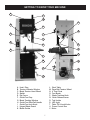
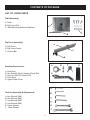
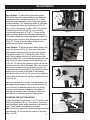
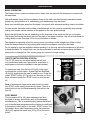
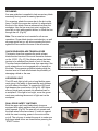
10-351
14” Professional Bandsaw
4001824
Operator’s Manual
Record the serial number and date of purchase in your manual for future reference.
Serial Number: _________________________
Date of purchase: _________________________
For technical support or parts questions, email [email protected] or call toll free at (877)884-5167
10-351M1
www.rikontools.com
TABLE OF CONTENTS
Specifications.....................................................................................................................2
Safety Instructions ........................................................................................................3 - 6
Getting To Know Your Machine .........................................................................................7
Contents of Package ....................................................................................................8 - 9
Assembly .........................................................................................................................10
Adjustments...............................................................................................................11 - 15
Operation ..................................................................................................................16 - 17
Maintenance....................................................................................................................18
Wiring Diagram ................................................................................................................18
Notes ...............................................................................................................................20
Troubleshooting ........................................................................................................19 - 23
Parts Explosions & Parts Lists ..................................................................................24 - 33
How To Guide for all Band Saw Blades ..........................................................................................34
Warranty ..........................................................................................................................35
SPECIFICATIONS
Motor .....................................................................................3 HP, TEFC
Motor Speed (no load).............................................................1700 RPM
Volts ............................................................................................... 220 V
Amps, Hertz .......................................................................12.9 A, 60 Hz
Blade Length ..................................................................124” (3150 mm)
Blade Width .............................................................1/4” - 1” (6 - 25 mm)
Blade Speeds (2) ............................................2132 ft/min or 4101 ft/min
Table Size .................................................21” x 19” (535 mm x 485 mm)
Table Tilt ................................................................. Left -100 , Right 450
Maximum Cutting Width (throat) ................................13-9/16” (345 mm)
Maximum Cuttng Depth (height) .............................. 13-15/16” (356 mm)
Table Height .................................................................36-1/4” (921 mm)
Fence Height ................................................................. 4-1/2” (115 mm)
Fence Length .............................................................. 19-3/4” (502 mm)
Dust Ports (2) ...................................................... 4” Diameter (100 mm)
Overall Size ......................... 75” x 30” x 29-5/8” (1905 x 762 x 752 mm)
2
SAFETY INSTRUCTIONS
IMPORTANT! Safety is the single most important consideration in the operation of this equipment. The following
instructions must be followed at all times. Failure to follow all instructions listed below may result in electric shock, fire,
and/or serious personal injury.
There are certain applications for which this tool was designed. We strongly recommend that this tool not be modified and/
or used for any other application other than that for which it was designed. If you have any questions about its application,
do not use the tool until you have contacted us and we have advised you.
SAFETY SYMBOLS
SAFETY ALERT SYMBOL: Indicates DANGER, WARNING, or CAUTION. This symbol may be used in
conjunction with other symbols or pictographs.
Indicates an imminently hazardous situation, which, if not avoided, could result in death or serious injury.
Indicates a potentially hazardous situation, which, if not avoided, could result in death or serious injury.
Indicates a potentially hazardous situation, which, if not avoided, could result in minor or moderate injury.
NOTICE: Shown without Safety Alert Symbol indicates a situation that may result in property damage.
GENERAL SAFETY
KNOW YOUR POWER TOOL. Read the owner’s manual
carefully. Learn the tool’s applications, work capabilities,
and its specific potential hazards.
4. AVOID A DANGEROUS WORKING ENVIRONMENT.
DO NOT use electrical tools in a damp environment or
expose them to rain.
BEFORE USING YOUR MACHINE
5. DO NOT use electrical tools in the presence of
flammable liquids or gasses.
To avoid serious injury and damage to the tool, read and
follow all of the Safety and Operating Instructions before
operating the machine.
6. ALWAYS keep the work area clean, well lit, and
organized. DO NOT work in an environment with floor
surfaces that are slippery from debris, grease, and wax.
1. Some dust created by using power tools contains
chemicals known to the State of California to cause cancer,
birth defects, or other reproductive harm.
Some examples of these chemicals are:
• Lead from lead-based paints.
• Crystalline silica from bricks, cement, and other
• masonry products.
• Arsenic and chromium from
chemically treated lumber.
Your risk from these exposures varies, depending on how
often you do this type of work. To reduce your exposure to
these chemicals: work in a well ventilated area and work
with approved safety equipment, such as those dust masks
that are specially designed to filter out microscopic
particles.
7. KEEP VISITORS AND CHILDREN AWAY. DO NOT
permit people to be in the immediate work area, especially
when the electrical tool is operating.
8. DO NOT FORCE THE TOOL to perform an operation
for which it was not designed. It will do a safer and higher
quality job by only performing operations for which the tool
was intended.
9. WEAR PROPER CLOTHING. DO NOT wear loose
clothing, gloves, neckties, or jewelry. These items can get
caught in the machine during operations and pull the
operator into the moving parts. The user must wear a
protective cover on their hair, if the hair is long, to prevent it
from contacting any moving parts.
2. READ the entire Owner’s Manual. LEARN how to use
the tool for its intended applications.
10. CHILDPROOF THE WORKSHOP AREA by removing
switch keys, unplugging tools from the electrical
receptacles, and using padlocks.
3. GROUND ALL TOOLS. If the tool is supplied with a 3
prong plug, it must be plugged into a 3-contact electrical
receptacle. The 3rd prong is used to ground the tool and
provide protection against accidental electric shock. DO
NOT remove the 3rd prong. See Grounding Instructions on
the following pages.
11. ALWAYS UNPLUG THE TOOL FROM THE
ELECTRICAL RECEPTACLE when making adjustments,
changing parts or performing any maintenance.
3
SAFETY INSTRUCTIONS
12. KEEP PROTECTIVE GUARDS IN PLACE AND IN
WORKING ORDER.
25. ALWAYS WEAR A DUST MASK TO PREVENT
INHALING DANGEROUS DUST OR AIRBORNE
PARTICLES, including wood dust, crystalline silica dust
and asbestos dust. Direct particles away from face and
body. Always operate tool in well ventilated area and
provide for proper dust removal. Use dust collection
system wherever possible. Exposure to the dust may cause
serious and permanent respiratory or other injury, including silicosis (a serious lung disease), cancer, and death.
Avoid breathing the dust, and avoid prolonged contact with
dust. Allowing dust to get into your mouth or eyes, or lay
on your skin may promote absorption of harmful material.
Always use properly fitting NIOSH/OSHA approved respiratory protection appropriate for the dust exposure, and wash
exposed areas with soap and water.
13. AVOID ACCIDENTAL STARTING. Make sure that the
power switch is in the “OFF” position before plugging in the
power cord to the electrical receptacle.
14. REMOVE ALL MAINTENANCE TOOLS from the
immediate area prior to turning “ON” the machine.
15. USE ONLY RECOMMENDED ACCESSORIES. Use
of incorrect or improper accessories could cause serious
injury to the operator and cause damage to the tool. If in
doubt, check the instruction manual that comes with that
particular accessory.
16. NEVER LEAVE A RUNNING TOOL UNATTENDED.
Turn the power switch to the “OFF” position. DO NOT
leave the tool until it has come to a complete stop.
26. USE A PROPER EXTENSION CORD IN GOOD
CONDITION. When using an extension cord, be sure to
use one heavy enough to carry the current your product
will draw. The table on the following page shows the correct size to use depending on cord length and nameplate
amperage rating. If in doubt, use the next heavier gauge.
The smaller the gauge number, the larger diameter of the
extension cord. If in doubt of the proper size of an extension cord, use a shorter and thicker cord. An undersized
cord will cause a drop in line voltage resulting in a loss of
power and overheating.
USE ONLY A 3-WIRE EXTENSION CORD THAT HAS
A 3-PRONG GROUNDING PLUG AND A 3-POLE
RECEPTACLE THAT ACCEPTS THE TOOL’S PLUG.
17. DO NOT STAND ON A TOOL. Serious injury could
result if the tool tips over, or you accidentally contact the
tool.
18. DO NOT store anything above or near the tool where
anyone might try to stand on the tool to reach it.
19. MAINTAIN YOUR BALANCE. DO NOT extend
yourself over the tool. Wear oil resistant rubber soled
shoes. Keep floor clear of debris, grease, and wax.
20. MAINTAIN TOOLS WITH CARE. Always keep tools
clean and in good working order. Keep all blades and tool
bits sharp, dress grinding wheels and change other
abrasive accessories when worn.
27. ADDITIONAL INFORMATION regarding the safe and
proper operation of this product is available from:
•
Power Tool Institute
1300 Summer Avenue
Cleveland, OH 44115-2851
www.powertoolinstitute.org
•
National Safety Council
1121 Spring Lake Drive
Itasca, IL 60143-3201
www.nsc.org
•
23. SECURE ALL WORK. Use clamps or jigs to secure
the workpiece. This is safer than attempting to hold the
workpiece with your hands.
American National Standards Institute
25 West 43rd Street, 4th Floor
New York, NY 10036
www.ansi.org
•
24. STAY ALERT, WATCH WHAT YOU ARE DOING,
AND USE COMMON SENSE WHEN OPERATING A
POWER TOOL.
A moment of inattention while operating power tools may
result in serious personal injury.
ANSI 01.1 Safety Requirements for
Woodworking Machines and the
U.S. Department of Labor regulations
www.osha.gov
28. SAVE THESE INSTRUCTIONS. Refer to them
frequently and use them to instruct others.
21. EACH AND EVERY TIME, CHECK FOR DAMAGED
PARTS PRIOR TO USING THE TOOL. Carefully check all
guards to see that they operate properly, are not damaged,
and perform their intended functions. Check for alignment,
binding or breaking of moving parts. A guard or other part
that is damaged should be immediately repaired or
replaced.
22. DO NOT OPERATE TOOL WHILE TIRED, OR
UNDER THE INFLUENCE OF DRUGS, MEDICATION
OR ALCOHOL.
4
SAFETY INSTRUCTIONS
ELECTRICAL SAFETY
EXTENSION CORDS
Keep the extension cord clear of the
working area. Position the cord so that it will not get
caught on lumber, tools or other obstructions while
you are working with a power tool.
THIS TOOL REQUIRES THE INSTALLATION OF
A 220V PLUG (NOT INCLUDED), AND MUST BE
GROUNDED WHILE IN USE TO PROTECT THE
OPERATOR FROM ELECTRIC SHOCK.
Check extension cords before each
use. If damaged replace immediately. Never use a tool
with a damaged cord, since touching the damaged
area could cause electrical shock, resulting in serious
injury.
IN THE EVENT OF A MALFUNCTION OR BREAKDOWN, grounding provides the path of least resistance
for electric current and reduces the risk of electric
shock. This tool is equipped with an electric cord that
has an equipment grounding conductor and requires
a grounding plug (not included). The plug MUST be
plugged into a matching electrical receptacle that is
properly installed and grounded in accordance with
ALL local codes and ordinances.
Use a proper extension cord. Only use cords listed by
Underwriters Laboratories (UL). Other extension cords can
cause a drop in line voltage, resulting in a loss of power
and overheating of tool. When operating a power tool
outdoors, use an outdoor extension cord marked “W-A” or
“W”. These cords are rated for outdoor use and reduce the
risk of electric shock.
DO NOT MODIFY ANY PLUG. If it will not fit the electrical
receptacle, have the proper electrical receptacle installed
by a qualified electrician.
IMPROPER ELECTRICAL CONNECTION of the
equipment grounding conductor can result in risk of
electric shock. The conductor with the green insulation
(with or without yellow stripes) is the equipment grounding
conductor. DO NOT connect the equipment grounding
conductor to a live terminal if repair or replacement of the
electric cord or plug is necessary.
CHECK with a qualified electrician or service personnel if
you do not completely understand the grounding
instructions, or if you are not sure the tool is properly
grounded when installing or replacing a plug.
THIS SYMBOL DESIGNATES THAT
THIS TOOL IS LISTED BY THE
INTERTEK TESTING SERVICES,
TO UNITED STATES AND
CANADIAN STANDARDS.
USE ONLY A 3-WIRE EXTENSION CORD THAT HAS A
3-PRONG GROUNDING PLUG AND A 3-POLE
RECEPTACLE THAT ACCEPTS THE TOOL’S PLUG. *
REPLACE A DAMAGED OR WORN CORD
IMMEDIATELY.
Sample of 220 volt plug required for this machine.
This tool is intended for use on a circuit that has a 220
volt electrical receptacle. FIGURE 1 shows the type of the
220v, 3-wire electrical plug and electrical receptacle that
has a grounding conductor that is required.
Consult a qualified
electrician if the
distance of the
machine from the
electrical panel is
greater than 30 feet.
* Canadian electrical codes require extension cords to
be certified SJT type or better.
** The use of an adapter in Canada is not acceptable.
Figure 1
5
SAFETY INSTRUCTIONS
SPECIFIC SAFETY INSTRUCTIONS FOR BAND SAWS
1. Always allow the bandsaw blade to stop before removing scrap pieces from table.
2. Always keep hands and fingers away from the blade.
3. Never attempt to saw stock that does not have a flat surface, unless a suitable support is used.
4. Always hold material firmly and feed it into the blade at a moderate speed.
5. Always turn off the machine if the material is to be backed out of an uncompleted cut.
6. Adjust the upper guide about 1/8” to 1/4” above the material being cut.
7. Check for proper blade size and type for thickness and type of material being cut.
8. Make sure that the blade tension and blade tracking are properly adjusted.
9. Make “relief” cuts before cutting long curves.
10. Release blade tension when the saw will not be used for a long period of time.
California Proposition 65 Warning
WARNING: Some dust created by power sanding, sawing, grinding, drilling, and other construction
activities contains chemicals known to the State of California to cause cancer and birth defects or
other reproductive harm.Your risk from exposure to these chemicals varies, depending on how
often you do this type of work. To reduce your exposure, work in a well-ventilated area and with
approved safety equipment, such as dust masks that are specially designed to filter out microscopic
particles.
For more detailed information about California Proposition 65 log onto rikontools.com.
This owner’s manual is not a teaching aid. Use of this owner’s manual is intended to
show assembly, adjustments, and general use.
SAVE THESE INSTRUCTIONS.
Refer to them often.
NOTE: The specifications, photographs, drawings and information in this manual represent the current
model when the manual was prepared. Changes and improvements may be made at any time, with no
obligation on the part of Rikon Power Tools, Inc. to modify previously delivered units. Reasonable care
has been taken to ensure that the information in this manual is correct, to provide you with the guidelines
for the proper safety, assembly and operation of this machine.
6
GETTING TO KNOW YOUR MACHINE
A
F
G
P
B
H
Q
C
I
J
D
R
K
S
E
T
L
M
U
N
V
O
A. Hoist Ring
B. Tension Indicator Window
C. Blade Tension Hand Wheel
D. Switch
E. Rip Fence
F. Guide Post Cap
G. Blade Tracking Window
H. Guide Post Rise/Fall Handle
I. Guide Post Lock Knob
J. Hinged Blade Guard
K. Blade Guides
L. Work Table
M. Drive Belt Tension Wheel
N. 4” Dust Ports
O. Foot Break
P. Blade Tracking Knob
Q. Quick Release Lever
R. Tool Holder
S. LED Light
T. Table Tilt & Lock Knobs
U. Power Control Box
V. Motor
7
CONTENTS OF PACKAGE
Model 10-351 14” Professional Bandsaw is shipped complete in one crate.
Unpacking and Checking Contents
a. Separate all “loose parts” from packaging materials and check each item with “Table of Loose
Parts” to make sure all items are accounted for, before discarding any packaging material.
b. Thread hoist ring into threading hole on top of Bandsaw frame. This allows the user to connect
a properly secured hoist mechanism to lift the Bandsaw.
c. With the help of another person or by installing hoist ring, unbolt the Bandsaw from the packing
pallet. Properly lift the Bandsaw off the packing pallet and place on level floor.
d. Remove protective oil that is applied to the table. Use any ordinary house hold type grease or
spot remover.
e. Apply a coat of paste wax to the table to prevent rust. Wipe all parts thoroughly with a clean
dry cloth.
TABLE OF LOOSE PARTS
ItemPart Name
A
B
C
D
E
Bandsaw Assembly
Table with Insert & Fence Rail
Owner’s Manual
Parts Package 1
Parts Package 2
A
B
D
E
C
8
CONTENTS OF PACKAGE
LIST OF LOOSE PARTS
Table Assembly:
A. Table
B. Rip Fence Rail
C. Table Mounting Bolts and Washers
A
C
B
Rip Fence Assembly:
A
A. Rip Fence
B. Rip Fence Carrier
C. Re-saw Bar
C
B
A
Bandsaw Accessories:
A. Hoist Ring
B. Hex Screw & Nut for Hanging Push Stick
C. Keys for ON/OFF Switch Lock
D. Push Stick
E. Upper Guide Cover
D
A
Tools for Assembly & Adjustments:
B
C
A. Hex Wrench 3MM
B. Hex Wrench 4MM
C. Hex Wrench 5MM
D. Hex Wrench 6MM
E. 10mm Wrench
F. 13mm Wrench
D
E
F
9
B
C
E
ASSEMBLY
INSTALLING THE WORK TABLE
NOTE: The table leveling bar is pre-installed at the
factory to hold table steady during shipping. It must be
removed before assembling the work table to the saw.
The work table is fastened to the upper table trunnion
with four M8x20 hex bolts and four M8 flat washers.
With the help of another person lift the work table onto
the upper trunnion. Slide the blade through the blade
slot until the threaded holes of the table align with the
through holes in the upper table trunnion. Tighten table
in place (Circled, Fig.1) with supplied fasteners using
the 13mm wrench provided.
Underside of Table
B
Figure 1
INSTALLING THE TABLE LEVELING BAR
Locate the table leveling bar, two wing knobs and two
washers (A-Fig.2 Inset).
Insert a wing knob and washer through the left hole of
the table leveling bar and into the threaded hole on the
left side of the blade slot (B-Fig.1). Make sure that the
opening of the slot on the right side of the table leveling
bar faces toward the table trunnion. This will allow the
table leveling bar to open outward from the bandsaw.
Table Leveling Bar
图1
Underside of Table
A
Figure 2
图1
RIP FENCE RAIL
The Rip Fence Rail has been pre-assembled to the
work table for shipping. After mounting the work table
to the trunnions (see above instructions), the rail should
be checked to ensure that it is still properly tightened
in place to the table. If adjustments are needed, loosen
and/or re-tighten the four hex nuts on the fence bar
support shafts that extend through the table’s front skirt
edge (A-Fig.3 ). The four nuts will also be used for drift
adjustments, described on page 15.
NOTE: It may be necessary to open the table leveling
bar to gain access to the right side fence bar stud.
A
A
Fence Rail
Figure 3
UPPER GUIDE RAIL COVER
Guide Rail Cover
Install the plastic Guide Rail Cover (#88) into the square
hole on the top of the upper frame. This cap protects the
guide post (#195) when it raises above the saw.
10
Bandsaw
Figure 4
ADJUSTMENTS
TOOL STORAGE
Tool Holder
Storage for the “L” Hex Wrenches is provided for quick
access when adjustments are needed. Place the (4)
wrenches (3mm, 4mm, 5mm and 6mm) in the tool
holder on the rear column support (Fig.5).
A Hex Socket Screw and Nut (#34, 35) are provided
to hang the push stick. Install this hardware on the left
side of the column, in the prepared threaded hole.
Figure 5
SETTING THE TABLE SQUARE TO SAW BLADE
The table may be set at 90° to the saw blade sides
by adjusting the table stop screw (A-Fig.6) under the
table. The table stop screw rests on the top of the
quick release adjustment stop (B-Fig.6). First loosen
the locking nut (C-Fig.6) and set a square between
the blade and the work table. Adjust the table stop
screw (A-Fig.6) until the table and blade are set at 90°.
Retighten the locking nut (A-Fig.6) making sure that the
setting is maintained.
The table may also be set at 90° to the back of the saw
blade by adjusting the four trunnion micro adjustment
screws found in the base of the lower trunnion (A-Fig.7).
Slightly loosen part #134 mounting bolt (refer to parts
explosion on page 28 of this manual). Using the 3mm
“L” wrench provided, turn the trunnion micro adjusting
screws #266, as needed, to achieve desired setting.
Turning the screws clockwise will raise the trunnion;
counterclockwise will lower. Check table for 90° and
tighten part #134.
C
A
B
Figure 6
Mounting Bolt
Location
A
Underside of Table
Figure 7
NOTE: The Trunnion (Fig. 7) is shown removed from
bandsaw for clarity. Micro adjusting screws are raised
to exaggerate their location. Only two of the four micro
adjusting screws are shown.
B
TILTING THE TABLE
Loosen the lock handle (A-Fig.8) on the table trunnion.
Turn the table tilting knob (B-Fig.8) to adjust the table to
the desired angle. Use the angle indicator scale on the
trunnion bracket to find the desired angle. Retighten the
lock handle to secure the table.
11
A
Figure 8
ADJUSTMENTS
TRACKING THE BANDSAW BLADE
Unplug the bandsaw. Make sure the upper
and lower blade guides are adjusted away from the blade
and the tension scale is set to correspond to the width of
the blade you are using.
Open both doors. Loosen the lock lever (A-Fig.9) by
turning it counter clockwise and turn the blade tracking
knob (B-Fig.9) clockwise/counterclockwise while turning
the upper wheel by hand at least three rotations or until the
blade tracks centered on the wheel. Finally, tighten the lock
lever and close the doors.
A
B
Figure 9
Quick Release
ADJUSTING THE BLADE TENSION
The 10-351 has a Quick Release blade function which
allows for fast blade changing and tensioning. The Quick
Release Lever is shown in Figure 10.
To loosen the tension of the blade, turn the blade tension
hand wheel, or lever, (A-Fig.11) counter clockwise. To
tighten the tension of the blade, turn the blade tension
hand wheel clockwise. Tension the blade until the tension
readings correspond to the width of blade you are using by
viewing through the tension indicator window (B-Fig.11).
Quick Release Lever
Off
Off
Figure 10
Note: The blade tension scale may read differently due to
cut specifications of the blade manufacturer. It might be
necessary to increase/decrease tension up/down one size
on blade tension scale to achieve proper blade tension.
Always tension the blade with the quick
release lever in the “On” position. Failure to do so could
result in lack of blade tension or tension failure.
On
On
B
A
Figure 11
BLADE TENSION INDICATOR ADJUSTMENT
The Blade Tension Indicator arrow should be checked
and adjusted the first time the saw is set up and run, and
whenever a new blade is installed. The blade tension
indicator can also be adjusted for blades made from
thicker steel, or cut over/under in length by different
manufacturers.
With moderate tension on the blade loosen the two
adjusting screws with a Phillips-head screw driver
(A-Fig.12). Adjust the blade indicator up/down as needed
(B-Fig.12) and re-tighten the two adjusting screws.
12
A
B
Figure 12
ADJUSTMENTS
CHANGING THE BANDSAW BLADE
A
Unplug the machine from the electrical
supply. This ensures that the Bandsaw will not
accidentally turn on if the ON/OFF switch is bumped.
a) Open the top and bottom wheel doors by turning
the door locking knobs. (A-Fig.13)
Figure 13
b) Release the blade tension by moving the quick
release lever (Fig.14) from right to left. Open the
hinged door on the blade guard by loosening the
wing screw (A-Fig.15). Loosen then open the
table leveling bar (A-Fig.16).
c) Remove the saw blade by feeding it through the
slot in the table (B-Fig.16), upper and lower blade
guides and the slot in the spine of the machine.
Be careful not to cut yourself. Wear gloves for
protection.
d) When installing the new blade, ensure the blade
teeth are pointing downwards and towards you at
the position where the blade passes through the
table.
A
Off
On
图13
Quick Release Lever
Off
On
Figure 14
A
图14
e) Center the blade on both wheels.
f) Re-tension the new blade by moving the quick
release lever (Fig.14) left to right and check the
blade tracking. With your hand, slowly spin the
upper wheel clockwise three times. The blade
should run in the center of both wheels. Refer to
“Tracking the Saw Blade” on the previous page
for more details.
Hinged Door
Figure 15
g) Set the blade guides as described in the section
“Adjusting the Blade Guides” on the next page.
h) Close the hinged door on the blade guard
and tighten the wing screw (A-Fig.15). Close the
table leveling bar and tighten (A-Fig.16).
i) Close and lock both the wheel doors (A-Fig.14)
before reconnecting the power supply.
13
A
Figure 16
图16
ADJUSTMENTS
ADJUSTING THE BLADE GUIDES
A
Upper Guides: To adjust the upper blade guides,
first position the roller guides relative to the blade by
loosening the Allen cap head screw (A-Fig.17) and
sliding the guide assembly until the side roller guides
are approximately 1/16” behind the gullet of the blade,
then re-tighten the Allen cap head screw (A-Fig.17).
Next, set the roller guides to within 1/32” of the blade
by releasing the lock knob (B-Fig.17) and turning
the micro-adjusting knob (C-Fig.17). Do not set the
guides too close, as this will adversely affect the life
of the blade. When the correct adjustment is reached,
lock the guides in position by tightening the lock knob
(B-Fig.17). Finally, follow the same steps above to
position the rear thrust roller guide.
Lower Guides: To adjust the lower blade guides, first
loosen the hex nut (A-Fig.18), then move the lower
guide support casting to allow the side roller guides
to be approximately 1/16” behind the gullets of the
blade, and re-tighten the hex nut. Next set the roller
guides to within 1/32” of the blade by releasing the lock
knob (B-Fig.18) and turning the micro-adjusting knob
(C-Fig.18). Do not set the guides too close, as this will
adversely affect the life of the blade. When the correct
adjustment is reached, lock the guides in position by
re-tightening the lock knob (B-Fig.18). Adjust the thrust
bearing to be just clear of the back of the blade by
unlocking the hex nut (D-Fig.18), and turning adjusting
knob on rear of the trunnion. Finally, re-tighten the hex
nut (D-Fig.18).
Make sure the doors are closed, turn the bandsaw on
and inspect that the upper, lower and thrust bearings
are not turning. All bearings should not turn unless
pressure from workpiece is applied to the blade. If
bearings are turning under no pressure, repeat the
steps above to correctly adjust the blade guides.
ADJUSTING THE CUTTING HEIGHT
Loosen the guidepost lock knob (A-Fig.19) and turn the
guidepost handwheel (B-Fig.19) to raise or lower the
guide post/upper blade guide assembly to the desired
height. Then tighten the guidepost lock knob.
Note: The bottom edge of the guide bearings should be
approximately 1/4” above the top surface of the work
piece. (Fig.20)
14
B
C
Figure 17
D
B
A
C
Figure 18
B
A
Figure 19
Approximately
1/4”
Figure 20
ADJUSTMENTS
CHANGING THE BLADE SPEED PULLEY SETTING
Before changing the speed, always
make sure the machine has been unplugged from the
electrical supply.
A
The 10-351 has two pulley speed ranges, low speed
(2132 ft/min) and high speed (4101 ft/min).
The lower wheel (A-Fig.21) and the motor shaft have
twin multi-vee pulleys (B-Fig.21). A flat ribbed “J” belt
(C-Fig.21) passes around the wheel pulley, motor pulley
and belt tension pulley. The belt tension is released and
applied by using the handwheel (D-Fig.21).
For the high speed, the belt should be fitted to the rear
pulley on both the motor and the wheel (A-Fig.22).
(Large pulley on the motor, small pulley on the wheel)
C
D
B
Tension
Pulley
Figure 21
For the low speed, the belt should be fitted to the front
pulley on both the motor and wheel (B-Fig.22).
(Small pulley on the motor, large pulley on the wheel)
SETTING THE DRIVE BELT TENSION
A
To properly adjust belt tension, turn the hand-wheel
(D-Fig.21) until there is 3/8” to 1/2” deflection in the flat
ribbed “J” belt.
ADJUSTING THE RIP FENCE FOR DRIFT
B
Figure 22
Align the fence assembly, in or out, until it is parallel
with the side of the blade by turning the adjustment
collars and the fence bolts accordingly (A-Fig.23). If the
mounting bolts have been tightened, these will need
loosened off before this adjustment can be made.
The same adjustment can be made to compensate for
blade drift.
Check that the fence is 90 degrees to the table using
a suitable square. If no adjustments are needed, fully
tighten the nuts that secure the fence rail (bar).
If an adjustment is required, raise or lower either side of
the fence rail until the fence body is 90 degrees to the
table. Once set at 90 degrees, fully tighten the fence rail
(bar) nuts.
15
A
Movement
Top View of Table and Fence Rail
End View
Adjustment
Figure 23
OPERATION
BASIC OPERATION
The blade cuts on a continuous down-stroke. Never start the saw with the workpiece in contact with
the saw blade.
With both hands, firmly hold the workpiece down on the table, and feed it slowly towards the blade,
putting only light pressure on it, and keeping your hands away from the blade.
Keep your hands/fingers away from the blade. Use a push stick whenever working close to the blade.
For best results the blade must be sharp. A dull blade will not cut correctly, especially when straight
cutting, and causes excess pressure to be applied on the rear guide bearings.
Select the right blade for the job, depending on the thickness of the wood and the cut to be made.
The thinner and harder the wood, the finer the teeth of the blade should be. Use a fine tooth blade for
cutting sharp curves. See page 34 for more information on blades.
The machine is especially suited for cutting curves, but will also make straight cuts. When cutting,
follow the design marked out by pushing and turning the workpiece evenly into the blade.
Do not attempt to turn the workpiece without pushing it, as this may cause the workpiece to get stuck,
or bend the blade. For straight cuts, use the fence provided to feed the workpiece along the blade
slowly and in a straight line. Use a miter gauge for cross-cut or angle cutting.
ON/OFF SWITCH CONTROL STATION
The 10-351 has a key-on safety feature that will lock
out unauthorized users such as students, coworkers or
employees not trained or qualified to use the bandsaw.
To operate the saw, turn the key (A-Fig.24) to the right
to activate the control station. A green light will illuminate
(B-Fig.24) showing that the saw is ready for use. Press the
green “START” button (C-Fig.24) to turn the saw on. Once
work is finished, press the “STOP” button to turn the saw
off.
A
C
16
D
Figure 24
Note: If working with large pieces and not able to reach
the “STOP” button simply press the foot brake. There is a
switch built into the foot break assembly that will turn the
saw off.
FOOT BRAKE
The foot brake (A-Fig. 25), when depressed will slow
the blade to a stop, and will also shut off the bandsaw,
simultaneously. This is an added safety feature that allows
you to handle large workpieces without having to reach back
to the switch control station to the main “STOP” button. The
foot brake’s lever, when depressed, pivots the break pad
(B-Fig.25) against the break disc (C-Fig.25) on the motor
pulley.
B
C
B
A
Figure 25
OPERATION
RE-SAWING
A re-saw guide bar is supplied to help correct any blade
wandering during certain re-sawing operations.
For re-sawing, attach the re-saw bar to the slot on the
fence. Position the re-saw bar so that it is aligned with
the front of the blade. Draw a reference line down the
workpiece. Use the bar as a pivot point, angling the
wood left or right while against the bar, to follow the line
through the cut. (Fig.26)
Pivot Workpiece
Note: The re-saw bar is not needed for all re-saw
operations. Proper blade tension and selection, as well
as proper guide set up, will allow re-sawing flat stock
against the fence without the use of the re-saw bar.
Figure 26
QUICK RELEASE BLADE TENSION LEVER
The tension lever that operates the quick release
blade function has two of the most innovative features
on the 10-351. (Fig. 27) One feature allows the blade
tension to be released from back or front of the saw.
The other feature disables the saw from operating if the
quick release lever is not engaged with no tension on
the blade. This prevents accidental starting while the
tension lever is off and will eliminate the possibility of
damaging a blade or the saw.
LED WORK LIGHT
The LED work light is built onto a long flexible goose
neck giving it the ability to illuminate the work surface
on both sides of the blade. To operate the LED work
light depress the round button (A-Fig.28). LED lights
are very bright and can wash out reference lines on
a workpiece. If the light is too bright, move the goose
neck away reducing the amount of light cast on the
workpiece.
DUAL DOOR SAFETY SWITCHES
Both the upper and lower blade wheel doors are
equipped with safety switches that will shut the saw off
when opened. (Fig.29) The saw will not operate until
the blade wheel doors are closed. If a door is opened
while the saw is running, power to the motor will be
cut off. The only way to restart the saw is to make sure
both band wheel doors are closed before pressing the
“START” button.
17
Operate Quick Release from
the Front or Back of the Saw
Figure 27
A
Figure 28
Figure 29
MAINTENANCE
BEFORE CLEANING OR CARRYING OUT MAINTENANCE WORK, DISCONNECT
THE MACHINE FROM THE POWER SOURCE (WALL SOCKET). NEVER USE WATER OR OTHER
LIQUIDS TO CLEAN THE MACHINE. USE A BENCH BRUSH. DO NOT USE COMPRESSED
AIR NEAR BEARINGS. REGULAR MAINTENANCE OF THE MACHINE WILL PREVENT
UNNECESSARY PROBLEMS.
1. Keep the table clean to ensure accurate cutting.
2. Keep the outside of the machine clean to ensure accurate operation of all moving parts and
prevent excessive wear.
3. Keep the ventilation slots of the motor clean to prevent it from overheating.
4. Keep the inside of the machine (near the saw blade, etc.) clean to prevent accumulation of dust. Use dust collection, if possible.
5. To prolong the life of the blade, when the bandsaw is not in use for extended periods, release
the blade tension. Before reusing the bandsaw, ensure that the blade is re-tensioned and tracking is checked.
6. Keep guide bearings free of dust, clean frequently.
WIRING DIAGRAM
This machine must be grounded. Replacement of the power supply cable should
only be done by a qualified electrician.
Green
brown
Black
blue
White
blue
brown
LED VFD
black
Key Switch
red
Motor
KM-1 Motor Controller
Power light
black
LED light
brown
pedal brake
micro switch
blue
tension sys upper door
micro switch micro switch
lower door
micro switch
18
KM
micro switch
wire harness
TROUBLESHOOTING
FOR YOUR OWN SAFETY, ALWAYS TURN OFF AND UNPLUG THE MACHINE BEFORE
CARRYING OUT ANY TROUBLESHOOTING.
TROUBLE
PROBABLE CAUSE
REMEDY
The machine does not
1. No power supply.
work when switched on. 2. Defective switch.
Check the cable for breakage.
Contact your local dealer for repair.
The blade does not
move with the motor
running.
1. The quick release lever or
blade tension handwheel has
not been tightened.
2. The blade has come off one
of the wheels.
3. The saw blade has broken.
4. The drive belt has snapped.
Switch off the motor, tighten the quick release
lever or blade tension handwheel.
1. Fence for cutting not used.
2. Too fast feed rate.
Use a fence.
Put light pressure on the workpiece & make
sure the blade does not bend.
Use a new blade.
The blade does not cut
in a straight line.
The blade does not cut,
or cuts very slowly.
3. The blade teeth are dull or
damaged.
4. Blade guides not suitably
adjusted.
1. The teeth are dull, caused by
cutting hard material or long
use.
2. The blade was mounted in
the wrong direction.
Sawdust builds up
inside the machine.
Sawdust inside the
motor housing.
The machine does not
cut at 45o or 90o angles.
The blade cannot be
properly positioned on
the bandwheels.
Open the hinged door and check.
Replace the blade.
Replace the belt.
Adjust the blade guides (see the section on
page 14 and 21).
Replace the blade, use a 6 T.P.I. blade for
wood and soft materials. Use a 14 T.P.I.
blade for harder materials. A 14 T.P.I. blade
always cuts slower due to the finer teeth and
the slower cutting performance.
Fit the blade correctly.
1. This is normal
Clean the machine regularly. Open the
hinged door and remove the sawdust with a
vacuum cleaner.
1. Excessive dust build-up
on the machine exterior
components.
Clean the ventilating slots of the motor with
a vacuum cleaner. From time to time remove
the sawdust to prevent it from being sucked
into the housing
1. The table is not at right
angles to the blade.
2. The blade is dull or too much
pressure was put on the
workpiece.
Adjust the table.
1. The blade tracking knob
hasn’t been properly adjusted.
2. Inferior blade.
3. The wheels are not in
alignment.
Adjust the tracking knob (see page 12).
Replace the blade.
Adjust the lower wheel (see pages 22 & 23)
Contact Technical Support @ 877-884-5167
or [email protected].
Replace the blade or put less pressure on
the workpiece.
For parts or technical questions contact: [email protected] or 877-884-5167.
19
NOTES
Use this section to record maintenance, service and any calls to Technical Support.
TROUBLESHOOTING
CHANGING THE MOTOR DRIVE BELT
(Refer to “Frame Assembly” parts diagram on page 24)
Before changing the belt, make sure that the bandsaw is unplugged from the power source.
Release the saw blade tension from the drive belt by turning the quick release blade tension lever.
Release the drive belt tension by using the blade tension hand wheel (Part #62).
Remove the lower wheel (Wheel Assembly, Part #98) by removing the hex head bolt and washer in
the middle of the wheel’s hub. Carefully slide the lower wheel off of the lower wheel shaft, and at the
same time remove the saw blade from this wheel.
Remove the old drive belt from the wheel’s pulley, and install the new belt. Make sure that the ribs in
the drive belt are seated correctly in the pulley before reassembling and tensioning the drive belt.
Reverse the procedure to re-assemble the saw parts. Tension the drive belt until there is 3/8” to 1/2”
of deflection.
20
TROUBLESHOOTING
ADJUSTING THE UPPER BLADE GUIDE BEARINGS PARALLEL TO THE BLADE
(Refer to “Guide Post Assembly” parts diagram on page 32).
This step may not be necessary, it is factory preset. If adjustment is needed follow the steps below.
First slightly loosen part #226 Hex Bolt M8X20 (4 each) on rear of upper bandsaw housing. This will
allow you to adjust the micro adjustment screws #227 in part #224 Gear Bracket.
Next place a 3mm “L” wrench through the sight holes in part #198 Cover. Turning clockwise on the
micro adjustment screws in left two holes will adjust the left bearings to the right. Turning clockwise
on the micro adjustment screws in the right two holes will adjust the right bearings to the left. Check
bearings for parallel.
Lastly tighten parts #226 Hex Bolt (4) on back of bandsaw housing. Repeat steps if the bearings are
still not parallel.
ADJUSTING THE UPPER SIDE BEARINGS WHICH WILL NOT TRACK CLOSE TO
THE BLADE
(Refer to “Guide Post Assembly” parts diagram on page 32).
If the right or left upper guide bearings do not adjust to within 1/32” of the blade, the Guide Post (part
#195) may need adjustment.
First lower the Guide Post (part #195) all the way to the table.
Second slightly loosen parts #226 Hex Bolt M8X20 (4) on the back of the upper bandsaw cabinet
housing.
Next, swing the Guide Post (part #195) right or left until side guide bearings are properly spaced on
each side of blade, making sure that the blade will strike the center of the rear thrust bearing. Tighten
part #226 Hex Bolt M8X20 (4) on the back of the upper bandsaw cabinet housing.
Raise the Guide Post (part #195) seven inches off the table and check alignment. If side guide
bearings travel out of alignment repeat steps above. Raise the Guide Post (part #195) to the top of
the travel and check final alignment. Repeat steps above if necessary.
CHANGING BANDSAW TIRES
Use a putty knife to get underneath the tire and pull it up and away from the wheel. Work the putty
knife all the way around the wheel to loosen the tire. Then, use the putty knife as leverage to flip the
tire over and off of the wheel. Clean the inside of the groove, removing any dirt, debris or cement with
lacquer thinner.
Soak the replacement tire in warm water to make it more flexible. Dry the tire, and while it is still
warm, lay it on top of the wheel. Start by setting the tire into the wheel groove at the top of the wheel.
Using a putty knife, work the new tire around the wheel, making sure not to slice the tire. If rubber
cement is to be used as a binder, make sure to distribute it evenly. Having high spots between the
wheel and the tire will cause a vibration and effect blade tracking.
21
TROUBLESHOOTING
LOWER WHEEL ADJUSTMENTS
The following instructions will correct common blade issues related to the lower wheel’s alignment in
relation to the upper wheel. These adjustments will correct the blade position on the lower wheel and
blade oscillation (wobble). These are critical adjustments which affect the performance and accuracy
of the bandsaw.
PLEASE READ AND UNDERSTAND THESE STEPS THOROUGHLY BEFORE
MAKING ANY ADJUSTMENTS. FAILURE TO DO SO COULD DAMAGE THE MACHINE.
Please contact a tech support representative if you have questions before attempting these
adjustments.
RIKON Tech Support 877-884-5167 [email protected]
Release the blade tension completely before making any lower wheel adjustments. Pressure must be
released on the lower wheel to allow proper adjustments and to avoid damaging the machine.
If the blade is not running true, or it is not running on center of the lower wheel but is correct on the
upper wheel, then an adjustment to the wheel hub on the rear of the bandsaw is required.
12
The numbers shown on the rear hub photo
represent the positions on a clock face.
9
3
If a blade is tracking forward on the lower wheel
toward the door, follow these correction steps:
1.)
2.)
3.)
4.)
5.)
6.)
7.)
6
De-tension the saw blade.
Loosen 9 o’clock shaft bolt to take pressure off the shaft.
Loosen 12 o’clock shaft bolt one half rotation.
Tighten the 6 o’clock shaft bolt until the shaft touches the 12 o’clock adjusting bolt.
Lock all three shaft bolts.
Re-tension the saw blade and set the upper wheel to plumb by adjusting the tracking knob. Spin the upper wheel by hand and track the blade.
Repeat if further adjustment is necessary.
Incorrect
Correct
22
TROUBLESHOOTING
If a blade is tracking on the rear of the lower wheel, away from the door, follow these steps:
1.)
2.)
3.)
4.)
5.)
6.)
7.)
De-tension the saw blade.
Loosen 9 o’clock shaft bolt to take pressure off the shaft.
Loosen 6 o’clock shaft bolt one half rotation.
Tighten the 12 o’clock shaft bolt until the shaft touches the 6 o’clock adjusting bolt.
Lock all three shaft bolts.
Re-tension the saw blade and set the upper wheel to plumb by adjusting the tracking knob. Spin the upper wheel by hand and track the blade.
Repeat if further adjustment is necessary.
Incorrect
Correct
If a blade is moving back and forth (wobbling) follow
these steps:
Adjustment to the wheel hub on the rear of the bandsaw
is required.
1.)
2.)
3.)
4.)
5.)
6.)
7.)
8.)
9.)
De-tension the saw blade.
Loosen 6 o’clock shaft bolt to take pressure
off of the shaft.
Loosen 9 o’clock shaft bolt one half rotation.
Back and forth
Tighten the 3 o’clock shaft bolt until the shaft
movement.
touches the 9 o’clock adjusting bolt.
Lock all three shaft bolts.
Re-tension the saw blade and set the upper wheel to plumb by adjusting the tracking knob. Spin the upper wheel by hand and track the blade.
Start the bandsaw and check blade movement.
If movement has diminished then continue with the adjustment.
If movement is worse, reverse the adjustments in steps 3 and 4.
23
PARTS DIAGRAM
FRAME ASSEMBLY
NOTE: Please reference the
Manufacturer’s Part Number
when calling for Replacement
Parts.
For Parts under Warranty, the
serial number of your
machine is required.
24
PARTS LIST
FRAME ASSEMBLY
KEY NO.
1
2
3
4
5
6
7
8
9
10
11
12
13
14
15
16
17
18
19
20
22
23
24
25
26
27
28
29
30
31
32
33
34
35
36
37
38
39
40
41
42
43
44
45
46
47
48
49
50
51
52
53
DESCRIPTION
Ring
Tap Screw
Washer
Micro-Switch Cap
Switch
Micro-Switch Cover
Frame
Rivet
Leaf Spring
Rivet
Clear Window
Upper Door Assembly
Locking Nut
Tube
Hex Socket Screw M6X25
Stop Switch Box
Button
Key Switch
Pan Head Screw
Switch Plate
Pointer Plate
Pan Head Screw
Pointer
Flat Washer
Pointer Screw
Lower Door Assembly
Pan Head Screw
Micro-Switch
Hex Socket Screw M6X16
Flat Washer
Micro-Switch Plate
Nut
Hex Socket Screw M6X30
Nut
Spring
Hex Socket Screw M8X16
Hex Socket Screw M6X20
Spring Washer
Flat Washer
Pedal
Lever
Brake Block
Locking Nut
Flat Washer
Knob
Side Cover
Plate
Washer
Bolt
M6X16
Locking Nut
Hex Bolt M6X25
Brush
QTY MFG. PART NO.
1
4
4
2
2
2
1
4
2
8
2
1
4
2
4
1
1
1
4
1
1
6
1
2
1
1
2
1
2
2
2
2
1
1
1
2
4
2
2
1
1
1
1
1
2
1
1
2
2
2
1
1
KEY NO.
P10-351-1
P10-351-2
P10-351-3
P10-351-4
P10-351-5
P10-351-6
P10-351-7
P10-351-8
P10-351-9
P10-351-10
P10-351-11
P10-351-12
P10-351-13
P10-351-14
P10-351-15
P10-351-16
P10-351-17
P10-351-18
P10-351-19
P10-351-20
P10-351-22
P10-351-23
P10-351-24
P10-351-25
P10-351-26
P10-351-27
P10-351-28
P10-351-29
P10-351-30
P10-351-31
P10-351-32
P10-351-33
P10-351-34
P10-351-35
P10-351-36
P10-351-37
P10-351-38
P10-351-39
P10-351-40
P10-351-41
P10-351-42
P10-351-43
P10-351-44
P10-351-45
P10-351-46
P10-351-47
P10-351-48
P10-351-49
P10-351-50
P10-351-51
P10-351-52
P10-351-53
54
55
56
57
58
59
60
61
62
63
64
65
66
67
68
69
69A
70
71
72
73
74
75
76
77
78
79
80
81
82
83
84
85
86
87
88
89
90
91
92
93
94
253
254
255
256
257
258
259
260
261
25
DESCRIPTION
Washer
Hex Nut
M6
Locking Nut M8
Seat Pad
Screw Shaft
Drive Belt
Motor Pulley
Hex Screw M8X10
Small Hand Wheel
Retaining Ring
Screw
M5X8
Thread Rod
Hex Screw M8X20
Flat Washer
Washer
3HP Motor
Capacitor (not shown)
Hex Screw M8X25
Hex Nut
M8
Lower Bearing Bolt
Retaining Ring
Bearing
Sliding Shaft
Tension Wheel
Retaining Ring
Retaining Ring
Spring Washer
Nut
M27X2
Relay
Bushing
Micro-Switch
Screw M4X30
Light
Screw M4X15
Bushing
Upper Guide Cover
Thread Handle
Adjusting Knob
Indicator Light
Hex Socket Screw M5X10
Nut M4
Small Hand Wheel
Tool Holder
Screw
Plate
Wire Connector
Pan Head Screw
Pan Head Screw
Hex Nut
Bracket
Pan Head Screw
QTY MFG. PART NO.
1
1
1
1
1
1
1
2
1
2
2
1
4
4
4
1
1
4
4
1
1
2
1
1
1
1
1
1
1
4
1
2
1
2
1
1
1
1
1
2
4
1
1
2
1
1
2
2
1
1
1
P10-351-54
P10-351-55
P10-351-56
P10-351-57
P10-351-58
P10-351-59
P10-351-60
P10-351-61
P10-351-62
P10-351-63
P10-351-64
P10-351-65
P10-351-66
P10-351-67
P10-351-68
P10-351-69
P10-351-69A
P10-351-70
P10-351-71
P10-351-72
P10-351-73
P10-351-74
P10-351-75
P10-351-76
P10-351-77
P10-351-78
P10-351-79
P10-351-80
P10-351-81
P10-351-82
P10-351-83
P10-351-84
P10-351-85
P10-351-86
P10-351-87
P10-351-88
P10-351-89
P10-351-90
P10-351-91
P10-351-92
P10-351-93
P10-351-94
P10-351-253
P10-351-254
P10-351-255
P10-351-256
P10-351-257
P10-351-258
P10-351-259
P10-351-260
P10-351-261
PARTS DIAGRAM
WHEEL ASSEMBLY
26
PARTS LIST
WHEEL ASSEMBLY
KEY NO. DESCRIPTION
95
96
97
98
99
Washer
Hex Socket Screw
Bandsaw Blade
Lower Wheel
Bushing
100
101
102
103
Tire
Retaining Ring
Bearing
Upper Wheel
QTY
M8X16
MFG. PART NO.
2
2
1
1
2
P10-351-95
P10-351-96
P10-351-97
P10-351-98
P10-351-99
2
4
4
1
P10-351-100
P10-351-101
P10-351-102
P10-351-103
NOTE: Please reference the Manufacturer’s Part Number when calling for Replacement Parts.
For Parts under Warranty, the serial number of your machine is required.
27
PARTS DIAGRAM
TABLE & FENCE ASSEMBLY
28
TABLE & FENCE ASSEMBLY
KEY NO. DESCRIPTION
104
105
106
107
108
109
112
113
114
115
116
117
118
119
120
121
122
123
124
125
126
127
128
129
130
131
132
133
134
135
136
137
138
139
140
141
Rip Fence
Locking Plate
Washer
Spring Washer
Hex Socket Screw M6X16
Adjusting Knob Cap
Clip
Fence Rail
Support Shaft
Washer
Spring Washer
Hex Nut M8
Support Plate
Washer
Wing Knob
Hex Socket Screw M8X25
Bearing Bushing
Bearing
Washer
Support Rod
Nut M6
Nut M6
Adjusting Handle
Carriage Bolt
M12x90
Hex Socket Screw M5X10
Hex Socket Screw M5X50
Locking Nut
Washer
Screw
M12X30
Washer
Spring Washer
Lower Table Trunnion
Locking Handle
Locking Handle
Hex Socket Screw M6X10
Washer
PARTS LIST
QTY MFG. PART NO.
1
1
2
2
2
1
1
1
2
4
4
4
1
2
2
1
1
1
1
1
1
1
1
1
1
1
1
2
2
2
2
1
1
1
2
2
KEY NO. DESCRIPTION
P10-351-104
P10-351-105
P10-351-106
P10-351-107
P10-351-108
P10-351-109
P10-351-112
P10-351-113
P10-351-114
P10-351-115
P10-351-116
P10-351-117
P10-351-118
P10-351-119
P10-351-120
P10-351-121
P10-351-122
P10-351-123
P10-351-124
P10-351-125
P10-351-126
P10-351-127
P10-351-128
P10-351-129
P10-351-130
P10-351-131
P10-351-132
P10-351-133
P10-351-134
P10-351-135
P10-351-136
P10-351-137
P10-351-138
P10-351-139
P10-351-140
P10-351-141
142
143
144
145
146
147
148
149
150
151
152
153
154
155
156
157
158
159
160
161
243
244
245
246
247
248
249
250
251
252
262
263
264
265
266
QTY
Guide Shaft
Pointer
Pan Head Screw
Lower Guide Body
Washer
Ring
Tube
Threaded Shaft
Lock Plate
Retaining Ring
Bearing
Bushing
Hex Socket Screw M6X30
Upper Table Trunnion
Hex Screw
Washer
Nut
M8
Bolt
M8X50
Table
Table Insert
Shaft
Bolt
Bushing
Handle Assembly
Ruler
Ruler Carrier, left
Screw
Pan Head Screw
Flat Washer
Ruler Carrier, right
Shaft
Gear
Shaft
Pin
Set Screw
1
1
1
1
2
2
2
2
2
2
4
2
2
1
4
4
1
1
1
1
1
1
1
1
2
1
4
2
4
1
1
1
1
2
4
MFG. PART NO.
P10-351-142
P10-351-143
P10-351-144
P10-351-145
P10-351-146
P10-351-147
P10-351-148
P10-351-149
P10-351-150
P10-351-151
P10-351-152
P10-351-153
P10-351-154
P10-351-155
P10-351-156
P10-351-157
P10-351-158
P10-351-159
P10-351-160
P10-351-161
P10-351-243
P10-351-244
P10-351-245
P10-351-246
P10-351-247
P10-351-248
P10-351-249
P10-351-250
P10-351-251
P10-351-252
P10-351-262
P10-351-263
P10-351-264
P10-351-265
P10-351-266
NOTE: Please reference the Manufacturer’s Part Number when calling for Replacement Parts.
For Parts under Warranty, the serial number of your machine is required.
29
PARTS DIAGRAM
BLADE TENSION & TRACKING
30
PARTS LIST
BLADE TENSIONING & TRACKING
KEY NO. DESCRIPTION
164
165
166
167
168
169
170
171
172
173
174
175
176
177
178
179
180
181
182
183
184
185
186
187
188
189
190
191
192
193
QTY
Hex Nut M10
Spring Washer
Nut
M12
Spring Washer
Locking Nut
Flat Washer
Bolt
Threaded Rod
Slide Rod
Upper Wheel Shaft
Bushing
Switch Plate
Hex Socket Screw M5X10
Roll Pin
Threaded Plate
Threaded Rod
Bearing
Upper Block
Lower Block
Bearing
Support Plate
Hex Socket Screw M10X30
Knob Bushing
Knob Lever
Knob
Small Hand Wheel
Flat Washer
Spring
Washer
Hex Screw M6X12
2
4
2
2
2
2
2
1
2
1
1
1
1
1
1
1
1
1
1
1
1
2
1
2
2
1
2
10
2
1
MFG. PART NO.
P10-351-164
P10-351-165
P10-351-166
P10-351-167
P10-351-168
P10-351-169
P10-351-170
P10-351-171
P10-351-172
P10-351-173
P10-351-174
P10-351-175
P10-351-176
P10-351-177
P10-351-178
P10-351-179
P10-351-180
P10-351-181
P10-351-182
P10-351-183
P10-351-184
P10-351-185
P10-351-186
P10-351-187
P10-351-188
P10-351-189
P10-351-190
P10-351-191
P10-351-192
P10-351-193
NOTE: Please reference the Manufacturer’s Part Number when calling for Replacement Parts.
For Parts under Warranty, the serial number of your machine is required.
31
PARTS DIAGRAM
GUIDE POST ASSEMBLY
NOTE: Please reference
the Manufacturer’s Part
Number when calling for
Replacement Parts.
For Parts under Warranty,
the serial number of your
machine is required.
32
PARTS LIST
GUIDE POST ASSEMBLY
KEY NO. DESCRIPTION
195
196
197
198
199
200
201
202
203
204
205
206
207
208
209
210
211
212
213
214
215
216
217
218
219
220
221
222
223
224
225
226
227
228
229
230
231
232
233
234
235
236
237
238
239
240
241
QTY
Guide Post
Rack
Pan Head Screw
Cover
Hex Socket Screw M8X10
Blade Cover
Screw
Gear
Pan Head Screw
Plastic Window
Hex Nut M4
Hex Socket Screw M6X30
Bushing
Retaining Ring
Bearing
Upper Guide Body
Ring
Threaded Bushing
Threaded Shaft
Lock Plate
Washer
Threaded Shaft
Threaded Bushing
Bushing
Hex Socket Screw M6X20
Hex Socket Screw M8X12
Washer
Hex Socket Screw M5X10
Pan Head Screw
Gear Bracket
Washer
Hex Bolt M8X20
Screw
M6x12
Big Hand Wheel
Handle Assembly
Hex Screw M6X12
Hex Screw M5X8
Ring
Bushing
Rod
Locking Handle
Setting Plate
Pan Head Screw
Nut M6X15
Washer
Wing Knob
Support Bracket
33
1
1
3
1
4
1
1
1
4
1
4
2
2
3
5
1
3
2
2
3
3
1
1
1
1
2
2
2
1
1
4
4
4
1
1
1
1
1
1
1
1
1
2
1
1
1
1
MFG. PART NO.
P10-351-195
P10-351-196
P10-351-197
P10-351-198
P10-351-199
P10-351-200
P10-351-201
P10-351-202
P10-351-203
P10-351-204
P10-351-205
P10-351-206
P10-351-207
P10-351-208
P10-351-209
P10-351-210
P10-351-211
P10-351-212
P10-351-213
P10-351-214
P10-351-215
P10-351-216
P10-351-217
P10-351-218
P10-351-219
P10-351-220
P10-351-221
P10-351-222
P10-351-223
P10-351-224
P10-351-225
P10-351-226
P10-351-227
P10-351-228
P10-351-229
P10-351-230
P10-351-231
P10-351-232
P10-351-233
P10-351-234
P10-351-235
P10-351-236
P10-351-237
P10-351-238
P10-351-239
P10-351-240
P10-351-241
34
WARRANTY
WARRANTY
35
10-351
For more information:
16 Progress Rd
Billerica, MA 01821
877-884-5167 / 978-528-5380
[email protected]
10-351M1
www.rikontools.com