1
Disassembly and Reassembly
6
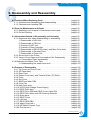
6. Disassembly and Reassembly
6.1 Cautions When Replacing Parts . . . . . . . . . . . . . . . . . . . . . . . . . . . . . . . . . page(6-2)
6.1.1 Cautions when assembling and disassembling . . . . . . . . . . . . . . . . . page(6-2)
6.1.2 Cautions when handling PBA . . . . . . . . . . . . . . . . . . . . . . . . . . . . . . . . . page(6-2)
6.2 Parts for Maintenance and Repair . . . . . . . . . . . . . . . . . . . . . . . . . . . . . . . page(6-3)
6.2.1 Replacing cycle of parts for maintenance and repair . . . . . . . . . . . . page(6-3)
6.2.2 Printer Cleaning . . . . . . . . . . . . . . . . . . . . . . . . . . . . . . . . . . . . . . . . . . . . . page(6-4)
6.3 Information Related in Disassembly and Assembly . . . . . . . . . . . . . . page(6-5)
6.3.1 Attentional item when disassembling or assembling . . . . . . . . . . . . page(6-5)
1) Disassemble of LSU Unit . . . . . . . . . . . . . . . . . . . . . . . . . . . . . . . . . . page(6-5)
2) Disassemble of ITB Unit . . . . . . . . . . . . . . . . . . . . . . . . . . . . . . . . . . . page(6-5)
3) Custody of OPC Unit . . . . . . . . . . . . . . . . . . . . . . . . . . . . . . . . . . . . . . page(6-5)
4) Custody of Toner Cartridge . . . . . . . . . . . . . . . . . . . . . . . . . . . . . . . . . page(6-5)
5) Disassemble of DEVE Drive Ass’y and Main Drive Ass’y . . . . . page(6-5)
6) Disassemble of Terminal Parts . . . . . . . . . . . . . . . . . . . . . . . . . . . . . page(6-5)
7) Disassemble of Fuser Unit . . . . . . . . . . . . . . . . . . . . . . . . . . . . . . . . . page(6-5)
6.3.2 Screw Used in the Printer . . . . . . . . . . . . . . . . . . . . . . . . . . . . . . . . . . . . page(6-6)
6.3.3 Various Cover Open and Consumption Part’ Disassembly . . . . . . . page(6-7)
>> Consumption Parts’ disassembly . . . . . . . . . . . . . . . . . . . . . . . . . . . page(6-7)
6.3.4 Replacing the Waste Toner Tank . . . . . . . . . . . . . . . . . . . . . . . . . . . . . . . . . page(6-10)
>> Disassembling the waste toner tank . . . . . . . . . . . . . . . . . . . . . . . . page(6-10)
6.4 Process of Disassembly . . . . . . . . . . . . . . . . . . . . . . . . . . . . . . . . . . . . . . . . page(6-12)
6.4.1 Top Cover and Front Cover . . . . . . . . . . . . . . . . . . . . . . . . . . . . . . . . . . . page(6-12)
6.4.2 OP Panel Ass’y . . . . . . . . . . . . . . . . . . . . . . . . . . . . . . . . . . . . . . . . . . . . . . page(6-16)
6.4.3 Rear Cover . . . . . . . . . . . . . . . . . . . . . . . . . . . . . . . . . . . . . . . . . . . . . . . . . . page(6-17)
6.4.4 Duplex Cover Ass’y and Transfer Roller (T2) Roller . . . . . . . . . . . . . page(6-19)
6.4.5 Fuser . . . . . . . . . . . . . . . . . . . . . . . . . . . . . . . . . . . . . . . . . . . . . . . . . . . . . . . page(6-21)
6.4.6 Exit Cover . . . . . . . . . . . . . . . . . . . . . . . . . . . . . . . . . . . . . . . . . . . . . . . . . . . page(6-23)
6.4.7 SMPS and Main PBA . . . . . . . . . . . . . . . . . . . . . . . . . . . . . . . . . . . . . . . . page(6-24)
6.4.8 Fuser Fan . . . . . . . . . . . . . . . . . . . . . . . . . . . . . . . . . . . . . . . . . . . . . . . . . . . page(6-27)
6.4.9 Main Drive Ass’y . . . . . . . . . . . . . . . . . . . . . . . . . . . . . . . . . . . . . . . . . . . . . page(6-28)
6.4.10 HVPS (High Voltage Power Supply) . . . . . . . . . . . . . . . . . . . . . . . . . . page(6-30)
6.4.11 DEVE Drive Ass’y . . . . . . . . . . . . . . . . . . . . . . . . . . . . . . . . . . . . . . . . . . . page(6-32)
6.4.12 DEVE Drive PBA and DEVE Cover Open S/W . . . . . . . . . . . . . . . . page(6-34)
6.4.13 DEVE Drive Motor and ITB Cleaning Solenoid . . . . . . . . . . . . . . . . page(6-36)
6.4.14 Erase lamp . . . . . . . . . . . . . . . . . . . . . . . . . . . . . . . . . . . . . . . . . . . . . . . . . page(6-37)
6.4.15 DEVE Cover . . . . . . . . . . . . . . . . . . . . . . . . . . . . . . . . . . . . . . . . . . . . . . . page(6-38)
6.4.16 LSU Unit . . . . . . . . . . . . . . . . . . . . . . . . . . . . . . . . . . . . . . . . . . . . . . . . . . . page(6-39)
6.4.17 DEVE OEM PBA . . . . . . . . . . . . . . . . . . . . . . . . . . . . . . . . . . . . . . . . . . . page(6-41)
6.4.18 Waste Toner Ass’y . . . . . . . . . . . . . . . . . . . . . . . . . . . . . . . . . . . . . . . . . . page(6-42)
6.4.19 MPT(Multi Purpose Tray) . . . . . . . . . . . . . . . . . . . . . . . . . . . . . page(6-44)
6.4.20 Pick-Up Ass’y . . . . . . . . . . . . . . . . . . . . . . . . . . . . . . . . . . . . . . page(6-45)
Traninung Manual
Samsung Electronics
6-1
Disassembly and Reassembly
6.1 Precautions when replacing parts
6.1.1 Precautions when assembling and disassembling
* Use only approved Samsung spare parts. Ensure that part number, product name, any voltage, current or
temperature rating are correct. Failure to do so could result in damage to the machine, circuit overload,
fire or electric shock.
* Do not make any unauthorized changes or additions to the printer, these could cause the printer to malfunction and create electric shock or fire hazards.
* Take care when dismantling the unit to note where each screw goes. There are 19 different screws. Use of
the wrong screw could lead to system failure, short circuit or electric shock.
* Do not disassemble the LSU unit. Once it is disassembled dust is admitted to the mirror chamber and will
seriously degrade print quality. There are no serviceable parts inside.
* Regularly check the condition of the power cord, plug and socket. Bad contacts could lead to overheating
and firfe. Damaged cables could lead to electric shock or unit malfunction.
6.1.2 Preautions when handling PBA
Static electricity can damage a PBA, always used approved anti-static precautions when
handling or storing a PBA.
>> Precautions when moving and storing PBA
1. Please keep PBA in a conductive case, anti-static bag, or wrapped in aluminum foil.
2. Do not store a PBA where it is exposed to direct sunlight.
>> Precautions when replacing PBA
1. Disconnect power connectors first, before disconnecting other cables
2. Do not touch any soldered connections, connector terminals or other electronic parts when handling
insulated parts.
>> Precautions when checking PBA
1. Before touching a PBA, please touch other grounded areas of the chassis to discharge any static electrical charge on the body.
2. Take care not to touch the PBA with your bare hands or metal objects as you could create a short circuit or get an electric shock. Take extra care when handling PBAs with moving parts fitted such as sensors, motors or lamps as they may get hot.
3. Take care when fitting, or removing, screws. Look out for hidden screws. Always ensure that the correct
screw is used and always ensure that when toothed washers are removed they are refitted in their original positions.
6.1.3 Releasing Plastic Latches
Many of the parts are held in place with plastic latches. The latches break easily; release them carefully.
To remove such parts, press the hook end of the latch away from the part to
which it is latched.
6-2
Service Manual
Samsung Electronics
Disassembly and Reassembly
6.2 Parts for Maintenance and Repair
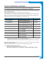
6.2.1 Replacing cycle of parts for maintenance and Repair
Some of the parts in this printer have a limited life, shorter than that of the whole machine. These parts
must be replaced periodically.
The table below shows the interval at which these parts should be replaced.
The table shows the life of each part, and is measured when using A4 paper. When servicing a machine
always check the status of these parts using the control panel and ensure that parts are replaced at the
appropriate times otherwise a general degradation in print quality will occur.
COMPONENT
REPLACEMENT CYCLE
REMARK
Toer Cartridge(Black)
intial(2,000 pages@5% coverage)
replacement(7,000 pages@5% coverage)
User replace
Toer Cartridge(Cyan)
intial(1,500 pages@5% coverage)
replacement(5,000 pages@5% coverage)
User replace
Toer Cartridge(Magenta)
intial(1,500 pages@5% coverage)
replacement(5,000 pagse@5% coverage)
User replace
Toer Cartridge(Yellow)
intial(1,500 pages@5% coverage)
replacement(5,000 pages@5% coverage)
User replace
OPC Unit
mono : 50,000 pages
color : 12,500 pages
User replace
ITB Unit(T1 Roller)
mono : 50,000 pages
color : 12,500 pages
User replace
Waste Toner Tank
3,000 Images
User replace
Fuser Unit
simplex : 100,000 pages
duplex : 50,000 pages
Engineer
Transfer Roller(T2 Roller)
simplex : 50,000 pages
duplex : 25,000 pages
Engineer
* Page: Counted value based on sides of paper printed (Duplex = 2 pages).
* Image: Counted value based on printed monochrome images.
* When printing a color section 1 page = 4 images. (i.e. each side is made up of 4 color images)
The life span of each of these parts is stored in memory. The amount of each 'life' used can be checked at
any time using the control panel.
When a part is replaced it is necessary to reset the 'life used' that is stored in memory.
* How to initialize a the value of part's life span:
From the control panel, select the following items in order:
Menu-Setup - Maintenance - Check other - (Select a desired part) - Reset
Service Manual
Samsung Electronics
6-3
Disassembly and Reassembly
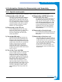
6.2.2 Printer Cleaning
A printer should be regularly cleaned, especially if it is used in a dusty environment. This will ensure that
print quality remains high and failure due to contamination of printing services is less likely to occur.
* Clean the printer with a soft, lint free, cloth dipped in a "Recommended cleaner"
"Recommended cleaner" can be purchased from our service center. (where available)
* Do not touch the transfer roller when cleaning the inside of the printer. Grease and oils from the
skin will contaminate the surface and reduce print quality.
* Do not touch transfer roller when cleaning inside of machine. If transfer roller gets dirty, printing
quality could be low.
* Please refer to the User Manual for cleaning instructions.
6-4
Service Manual
Samsung Electronics
Disassembly and Reassembly
6.3 Information Related to Disassembly and Assembly.
6.3.1 Special service parts
Never disassemble or adjust the items mentioned, a stock of these items should be maintained.
1) Disassembly of the LSU unit
There are no serviceable parts inside the
LSU. Alignment of the mirrors is critical.
Opening the LSU will allow dust into the
laser and significantly reduce print quality.
It is very dangerous to operate or service
a machine with the LSU open or system
interlocks disabled. Exposure to laser
radiation can cause blindness.
2) Disassembly of the ITB unit
Do not disassemble the ITB. The alignment of the home sensor is critical and is
set up in the factory on a special jig.
Incorrect re-assembly will cause print
quality degradation.
3) Care of the OPC unit
If an OPC unit is exposed to direct sunlight for a long time the parameters and
response of the electrostatic surface are
changed causing image transfer and print
quality issues. Also there is no protective
shutter on the OPC drum to prevent
scratching Please take extra care to
ensure the OPC drum is protected from
sunlight and physical contact when servicing the machine.
5) Disassembly of DEVE drive ass'y
and the main drive ass'y
The alignment of the drive mechanism is
critical and it has been set up in factory
using a jig and a driving gear. It is adjusted for the best gearing alignment. If the
motor is disassembled alignment would
not be maintained and this could cause
operational noise and image problems:
image alignment and toner distribution
may be affected.
6) Disassembly of terminal parts
Do not adjust the variable resistors on the
PBA. They have been already adjusted in
the factory.
7) Disassembly of the fuser unit
- The fuser melts toner onto the paper at
a high temperature: therefore, you need
to take special care not to get burned by
a hot fuser. When removing the fuser
from a set that has recently been operating you need to take extra care.
- Do not touch an AC line (Copper contact) on a main frame even after removing the fuser.
4) Care of the Toner cartridge
Toner cartridges contain an extremely fine
powder. Please keep toner cartridges
away from children. The toner powder
contained in the toner cartridge may be
harmful and if swallowed you should contact a doctor. Take care not to spill toner spillages should be cleaned with a
vacume cleaner and washed in could
water (hot water sets the toner). Do not
touch the developer roller surface as contamination will reduce print quality. Take
care not to damage the roller's surface
when installing or removing a toner cartridge.
Service Manual
Samsung Electronics
6-5
Disassembly and Reassembly
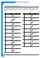
6.3.2 Screws used in the printer
The screws listed in the table below are used in this printer. Please ensure that, when
you disassemble the printer, you keep a note of which screw is used for which part and
that, when reassembling the printer, the correct screws are used in the appropriate
places.
NO
DESCRIPTION
SEC CODE
SPEC
NO
DESCRIPTION
SEC CODE
SPEC
S1
SCREW-MACHINE
6001-000485
2.6*4, GOLD
S11
SCREW-TAPTITE
6003-000269
3*6, GOLD
S2
SCREW-TAPPING
6002-000115
4*15, GOLD
S12
SCREW-TAPTITE
6003-001001
3*8, BLACK
S13 SCREW-MACHINE
6001-000568
3*8, SILVER
S14
SCREW-TAPTITE
6003-001256
4*10 SILVER
S15
SCREW-TAPTITE
6003-000261
3*6, GOLD
S16 SCREW-MACHINE
6003-001068
2*16, BLACK
S17
SCREW-TAPTITE
6003-000301
4*6, GOLD
S18
SCREW-SPICIAL
6009-001396
3*10, BLACK
S19
SCREW-TAPTITE
6003-000008
4*6, SILVER
S3
SCREW-TAPPING
6002-000175
3*8, GOLD
S4
SCREW-TAPTITE
6002-000308
2.6*6, GOLD
S5
SCREW-TAPTITE
6003-000119
3*8, BLACK
S6
SCREW-TAPTITE
6003-000152
2*10, GOLD
S7
SCREW-TAPTITE
6003-000179
3*6, GOLD
S8
SCREW-TAPTITE
6003-000196
3*10 SILVER
S9
SCREW-TAPTITE
S10 SCREW-ASS’Y MACH
6-6
6003-000266
3*6, GOLD
6006-001193
3*6, GOLD
Service Manual
Samsung Electronics
Disassembly and Reassembly
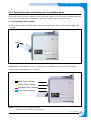
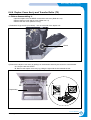
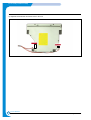
6.3.3 Opening Covers and replacing Consumable parts
This section shows you how to open the covers (front cover, DEVE cover, exit cover, and duplex cover) and
how to remove and replace the consumable parts (toner cartridge, ITB unit, and OPC drum).
>> Consumable parts removal
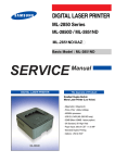
1) Pull the side handle to open the DEVE cover and then press down firmly until the toner cartridges are
ejected.
Pull
Caution: Before opening the exit cover, completely open the DEVE cover (eject the toner cartridges)
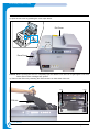
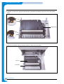
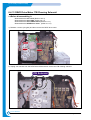
2) Removing a toner cartridge (K, Y, M, and C)
Black Toner Cartridge
Yellow Toner Cartridge
Margenta Toner Cartridge
Cyan Toner Cartridge
Caution: * Take care not to damage the rollers.
* Keep the toner cartridge on a flat surface.
Service Manual
Samsung Electronics
6-7
Disassembly and Reassembly
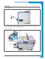
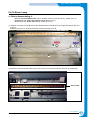
3) Open the exit cover by pressing the cover open button.
Exit Cover
Push
Deve Cover
Caution: Before opening the exit over completely open the DEVE cover until it is at right angles to the main
frame and the toner cartridges are ejected
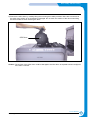
4) Remove the ITB unit by releasing the ITB lock levers on both sides of the unit.
Lever
Lever
ITB Unit
6-8
Service Manual
Samsung Electronics
Disassembly and Reassembly
5) Remove the OPC drum by carefully lifting the unit using the handle provided. Take care to ensure that
the OPC drum surface is not scratched or damaged. Do not touch the surface of the drum when lifting
the drum handle or when removing the drum.
OPC Drum
Caution: The surface of the OPC drum could be damaged if the OPC drum is exposed to direct sunlight for
more than 5 minutes.
Service Manual
Samsung Electronics
6-9
Disassembly and Reassembly
6.3.4 Replacing the Waste Toner Tank
>> Removing the waste toner tank
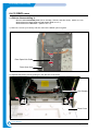
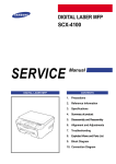
1) Push the top corners of the front cover to release the cover catches.
PUSH
2) Lift the hook at the top of the waste toner tank and gently pull the top edge of the waste tank forward. Lift
the tank out.
PULL
Caution: Be careful not to let toner spill from the waste toner tank.
6-10
Service Manual
Samsung Electronics
Disassembly and Reassembly
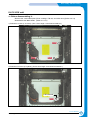
3) Remove the Toner Caps from the side of the tank and fit them to the tank inlets as shown below
Toner Cap
4) Fit a new waste toner tank.
Service Manual
Samsung Electronics
6-11
Disassembly and Reassembly
6.4 Disassembly Procedure
6.4.1 Top cover and Front cover
1) Remove the cassette.
Cassette
2) Open all of the covers in the following order:- Duplex cover - DEVE cover - Exit cover (Refer to 6.3.3)
Exit Cover
Deve Cover
Duplex Cover
6-12
Service Manual
Samsung Electronics
Disassembly and Reassembly
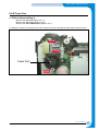
3) Release 2 screws (3*10 silver).
Top Cover
Screw
Screw
4) Take out the Top Cover as shown below.
Service Manual
Samsung Electronics
6-13
Disassembly and Reassembly
5) Push both of the top corners to release the catches and open the front cover and then remove the waste
toner tank. (Refer to 6.3.4)
PUSH
6) Release 7 screws (3*10 silver) located inside the front cover.
Release 2 screws (3*10 silver) located on the top of the front cover.
Screw
Screw
Screw
Screw
Screw
Screw
Screw
Screw
Screw
6-14
Service Manual
Samsung Electronics
Disassembly and Reassembly
7) Release 2 hooks on the right and the left side with a flat bladed screwdriver and then remove the front
cover. Take care to disconnect one harness connected to the frame.
Hook
Hook
Service Manual
Samsung Electronics
6-15
Disassembly and Reassembly
6.4.2 OP Panel Ass’y
>> Before disassembling it: Remove the front cover. (Refer to 6.4.1)
1) Release 3 screws ('A' below 3*8 black) and take out the OP panel ass'y.
2) Release 4 screws ('B' below 3*8 black) from the Panel PBA and remove the panel PBA.
3) Release 2 screws ('C' below 3*6 gold) from the LCD and then take out the LCD.
C
A
Screw
Screw
Screw
Screw
Screw
Screw
B
Screw
A
B
A
Screw
Screw
A : OP Panel Screw, 3 * 8 Black
B : Panel PBA Screw, 3 * 8 Black
C : LCD Screw, 3 * 6 Yellow
6-16
Service Manual
Samsung Electronics
Disassembly and Reassembly
6.4.3 Rear Cover
>> Before disassembling it:
*Open the duplex cover, the DEVE cover and the exit cover. (Refer to 6.3.3)
Remove the top cover. (Refer to 6.4.1)
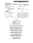
1) 1) Remove 10 screws.
A: Top 2 EA (3 * 10 Silver)
B: Side 3 EA (3 * 10 Silver)
C: Bottom 3 EA (4 * 10 Silver)
D: Rear 2 EA (3 * 10 Silver)
A
Screw
Screw
Screw
D
Screw
B
Screw
Screw
Screw
Screw
Screw
Screw
C
Service Manual
Samsung Electronics
6-17
Disassembly and Reassembly
2) Take out the Rear Cover as shown below.
6-18
Service Manual
Samsung Electronics
Disassembly and Reassembly
6.4.4 Duplex Cover Ass'y and Transfer Roller (T2)
>> Before disassembling it:
* Open the duplex cover, the DEVE cover and the exit cover. (Refer to 6.3.3)
* Remove the front cover and top cover. (Refer to 6.4.1)
* Remove the rear cover. (Refer to 6.4.3)1)
1) Release 2 hinge screws (3*10 silver) - one on each side of the duplex unit.
Screw
2) Remove the duplex cover ass'y by pulling it in the direction shown by the arrows in A and B below.
* A: Lift up the left side section.
* B: Remove the duplex cover ass'y by pulling the right side section towards the left.
A
A
B
B
Duplex Ass’y
Service Manual
Samsung Electronics
6-19
Disassembly and Reassembly
3) Release 4 hooks on the right and left side with a flat bladed screwdriver and then remove the duplex
ass'y.
Hook
Hook
Duplex Ass’y
Hook
Hook
4) Remove the transfer roller by turning the bush on each end of the roller
Duplex Ass’y
Transfer Roller
6-20
Service Manual
Samsung Electronics
Disassembly and Reassembly
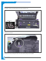
6.4.5 Fuser
1) Open the DEVE cover
Pull
Caution: Before opening the exit cover, completely open the DEVE cover until it is at right angles to the
main frame and the toner cartridges are ejected
2) Open the exit cover.
Exit Cover
Push
Deve Cover
Service Manual
Samsung Electronics
6-21
Disassembly and Reassembly
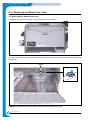
3) Release 5 screws (3*10 silver) and then remove the harness cover.
Screw
Screw
Harness Cover
Screw
Screw
Screw
4) Remove one harness.
Harness
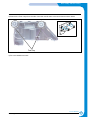
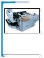
5) Remove the fuser by holding both sides of the fuser and then pulling the fuser upwards.
6-22
Service Manual
Samsung Electronics
Disassembly and Reassembly
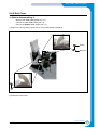
6.4.6 Exit Cover
>> Before disassembling it:
* Remove the front cover (Refer to 6.4.1)
* remove the rear cover (Refer to 6.4.3)
* remove the duplex cover (Refer to 6.4.4.)
1) Remove the E-ring and the hinge pin by using a flat bladed screwdriver.
E-Ring
Hinge Pin
2) Remove the exit cover.
Service Manual
Samsung Electronics
6-23
Disassembly and Reassembly
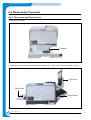
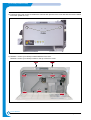
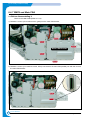
6.4.7 SMPS and Main PBA
>> Before disassembling it
*Remove the rear cover (Refer to 6.4.3)
1) Release 5 screws (3*6 machine screw, gold) from the main PBA bracket.
Screw
Screw
Screw
Main PBA Bracket
Screw
Screw
2) Release 2 screws (3*10 machine screw, silver) connected to the main PBA parallel port and then remove
the main PBA bracket
Screw
Screw
6-24
Service Manual
Samsung Electronics
Disassembly and Reassembly
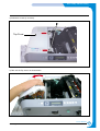
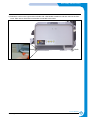
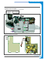
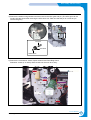
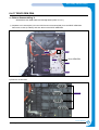
3) Release 5 screws from the SMPS.
Release one screw (3*10 silver) from the harness guide.
A: Right side 3EA (3 * 6 Gold)
B: Left side 1EA (3 * 10 Silver)
C: Bottom
1EA (4 * 10 Silver)
Harness Guide
Screw
Screw
A
A
Screw
B
Screw
SMPS
Screw
C
Screw
4) Remove 4 harnesses from the SMPS.
CON4
CON4
CON3
CON3
CON1
CON2
CON1 Fuse
CON2
Service Manual
Samsung Electronics
6-25
Disassembly and Reassembly
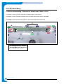
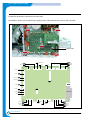
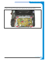
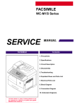
5) Remove all harness connected to the main PBA.
6) Release 5 screws (3*6 machine screw, gold) from the main PBA and then remove the main PBA.
Screw
Screw
Screw
Main PBA
Screw
Screw
EXIT CN19
CN10 ITB
CN17 WASTE TONER
CN15 TH3
DUPLEX CN24
CN11 PTL
CN7
HVPS
CN4
PANEL
T2 HOME CN26
BLDC1 CN27
FSR_ROLL CN28
FUSER_FAN CN29
CN9 NIC
USB
SMPS CN30
MP EMPT CN30
CN1
Parallel Port
MP SOL CN32
FEED CN33
PICK_UP CN25
CN16 SCF
CN12 LSU
CLT_FEED CN23
EMPT CN21
CN5
DRIVER
CN14 LSU SW
CN6 OPC KEY
CN8
EASER
CN35 LSU_FAN
6-26
Service Manual
Samsung Electronics
Disassembly and Reassembly
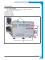
6.4.8 Fuser Fan
>> Before disassembling it:
* Remove the top cover (Refer to 6.4.1)
* Remove the rear cover (Refer to 6.4.3)
* Remove the main PBA bracket. (Refer to 6.4.7)
1) Release 3 screws (3*10 silver) remove one harness from the main PBA and then take out the fuser fan.
Screw
Screw
Fuser Fan
Screw
Service Manual
Samsung Electronics
6-27
Disassembly and Reassembly
6.4.9 Main Drive Ass’y
>>Before disassembling it:
*
*
*
*
Remove
Remove
Remove
Remove
the
the
the
the
rear cover (Refer to 6.4.3)
fuser (Refer to 6.4.5)
SMPS (Refer to 6.4.7)
fuser fan (Refer to 6.4.8)
1) Remove all harnesses from the harness guides.
2) Remove the SMPS cover bracket.
Bracket-Cover SMPS
3) Look inside the OPC drum cavity and locate the T2 cam. Remove the washer using tweezers and then
remove the T2 cam.
Cam-Drive
Washer-Plain
6-28
Service Manual
Samsung Electronics
Disassembly and Reassembly
4) Remove the washer using tweezers and then remove the OPC gear and pin. (The OPC gear can be
found inside the printer after removing the OPC drum unit. Take care that the pin is not lost as you
remove the gear.)
Pin-Drive
Gear-Drive
Washer-Plain
5) Remove the 3 harnesses Motor, Duplex solenoid and Feed Regi Clutch
Release 6 screws (3*10 silver) and then take out the main drive ass'y.
Screw
Screw
Screw
Harness
Screw
Screw
Screw
Service Manual
Samsung Electronics
6-29
Disassembly and Reassembly
6.4.10 HVPS (High Voltage Power Supply)
>>Before disassembling it:
* Disassemble the front cover & top cover (Refer to 6.4.1)
* Disassemble the rear cover (Refer to 6.4.3)
* Disassemble the main PBA bracket (Refer to 6.4.7.)
1) Remove one harness from the main PBA
CN7
HVPS
T1
CHARGER
T2
SUPPLY
USB
CN1(to Panel)
Parallel Port
CN2(to Deve)
<HVPS>
<Main PBA>
2) Remove one harness and 4 high-voltage harnesses from the HVPS.
Harness
Harness
Red
Black
Black Red
Harness
6-30
Service Manual
Samsung Electronics
Disassembly and Reassembly
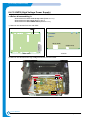
3) Remove 5 screws (3*6 machine screw, gold) and then remove the HVPS.
Screw
Screw
Screw
Screw
Screw
Service Manual
Samsung Electronics
6-31
Disassembly and Reassembly
6.4.11 DEVE drive ass’y
>>Before disassembling it:
* Disassemble the rear cover (Refer to 6.4.3)
* Disassemble the main PBA (Refer to 6.4.7)
1) Remove the main PBA shield and harness guide by releasing 5 screws
(2 EA 3*6 machine screw, gold; 2 EA 3*10 silver, 1 EA 4*10 silver)
Harness Guide
Screw
3x 10 White
Screw
Screw
3 x 6 Yellow
Main PBA Shield
Screw
Screw
4x 10 White
2) Remove the ground harness and the harness guide bracket by releasing 3 screws
(2 EA 3*6 machine screw, gold: 1 EA 4*10 silver).
Screw
B
Screw
Harness Guide Bracket
Screw
4 x 10 White
6-32
Service Manual
Samsung Electronics
Disassembly and Reassembly
3) Separate the harness from the DEVE motor.
Motor Harness
4) Release 5 screws (3*10 silver) from the DEVE drive ass'y.
Remove 4 harnesses connected to the DEVE drive PBA and then remove the DEVE drive ass'y.
Screw
SUPPLY
Screw
Screw
Screw
Screw
Harness
CLT_4TH CN5
CLT_3RD CN9
CLT-2ND CN4
CN8 CLT-1ST
Service Manual
Samsung Electronics
6-33
Disassembly and Reassembly
6.4.12 DEVE drive PBA and DEVE cover open S/W
>>Before disassembling it:
* Disassemble the rear cover (Refer to 6.4.3)
* Disassemble the main PBA (Refer to 6.4.7)
* Disassemble the main PBA bracket (Refer to 6.4.7.2)
1) Release 1 screw (3*10 silver) and then take out the DEVE cover open S/W.
Screw
Deve Cover Open S/W
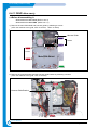
2) Remove all harnesses and 6 screws (3*10 silver) and then take out the DEVE drive PBA.
SUPPLY
Screw
Screw
Screw
BLCD_DEV CN1
SOL_T1_CLN CN10
CN7 SOL-3RD
Screw
CN2 SOL-2ND
SOL_1ST CN6
SOL_4TH CN3
CLT_4TH CN5
CLT_3RD CN9
CN1
Screw
Screw
CLT-2ND CN4
6-34
CN8 CLT-1ST
Service Manual
Samsung Electronics
Disassembly and Reassembly
3) Remove 4 high-voltage terminals.
Terminal
Terminal
Terminal
Terminal
Service Manual
Samsung Electronics
6-35
Disassembly and Reassembly
6.4.13 DEVE Drive Motor ITB Cleaning Solenoid
>>Before disassembling it:
*
*
*
*
Disassemble
Disassemble
Disassemble
Disassemble
the
the
the
the
rear cover (Refer to 6.4.3)
main PBA (Refer to 6.4.7)
main PBA bracket (Refer to 6.4.7)
DEVE drive motor. (Refer to 6.4.7)
1) Release 4 screws (3*6 gold) and then remove the DEVE drive motor.
Screw
Screw
Screw
Screw
2) Unplug one harness from the DEVE drive PBA and then remove the ITB cleaning solenoid.
ITB Solenoid
6-36
Service Manual
Samsung Electronics
Disassembly and Reassembly
6.4.14 Erase Lamp
>> Before disassembling it:
* Remove all consumable parts (Toner cartridge, ITB unit, and OPC drum) (Refer to 6.3.3)
* Disassemble the front cover and top cover (Refer to 6.4.1)
* Disassemble the waster toner ass’y. (Refer to 6.4.18)
1) Release 2 screws (4*15 gold) and 2 clips located close to the DEVE cover hinge and remove the LSU
cover: A
Release one screw (4*10 silver) and then remove the lamp cover: B
Screw
Screw
Screw
B
A
2) Release 2 clips and lift the eraser lamp ass'y, remove one harness and then remove the erase lamp.
Erase Lamp
Service Manual
Samsung Electronics
6-37
Disassembly and Reassembly
6.4.15 DEVE cover
>> Before disassembling it:
* Remove all consumable parts (Toner cartridge, ITB unit, and OPC drum) (Refer to 6.3.3)
* Disassemble the front cover and top cover (Refer to 6.4.1)
* Disassemble the LSU cover. (Refer to 6.4.14)
1) Remove 2 screws (3*10 silver) and then remove the DEVE open link guide.
Screw
Deve Open Link Guide
Screw
Deve Open Link
2) Separate the DEVE cover by pulling it in the direction of the arrow.
LSU Cleaner
Deve Cover
6-38
Service Manual
Samsung Electronics
Disassembly and Reassembly
6.4.16 LSU unit
>> Before disassembling it:
* Remove the consumable parts (Toner cartridge, ITB unit, and OPC drum) (Refer to 6.3.3)
* Disassemble the Deve cover. (Refer to 6.4.15)
1) Release 4 screws (4*10 silver). (Use a short length cross-head screwdriver.)
Screw
Screw
Screw
Screw
2) Release one screw (3*8 yellow). (Use a short length cross-head screwdriver.)
LSU Ground
Screw
Service Manual
Samsung Electronics
6-39
Disassembly and Reassembly
3) Separate 2 harnesses and remove the LSU unit.
Harness
Harness
6-40
Service Manual
Samsung Electronics
Disassembly and Reassembly
6.4.17 DEVE OEM PBA
>> Before disassembling it:
* Disassemble the front cover and the top cover. (Refer to 6.4.1)
1) Separate one harness(CN1) from the HVPS and one harness(CN2) from the DEVE OEM PBA.
Remove 6 screws (3*8 black) and then take out the DEVE OEM PBA.
Harness
Screw
Screw
Screw
Deve OEM PBA
Screw
Screw
Screw
2) Remove 12 terminals.
Terminals
Service Manual
Samsung Electronics
6-41
Disassembly and Reassembly
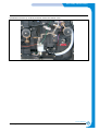
6.4.18 Waste toner ass’y
>> Before disassembling it:
* Disassemble a front cover and a top cover. (Refer to 6.4.1)
1) Release 6 screws (3*10 silver).
* Upper part: 4 screws * Lower part: 2 screws
Screw
Screw
Screw
Screw
Screw
Screw
2) Remove the waste toner ass'y by first reaching into the OPC cavity and lightly depressing the waste
toner receiver whilst at the same time gently pulling the waste toner motor assy away from the set. Once
the ass'y is released refer to the photograph and remove the ass'y.
OPC Lifter
Caution: * It is very likely that waste toner will be spilled when removing the waste toner ass'y.
6-42
Service Manual
Samsung Electronics
Disassembly and Reassembly
3) Release one screw (3*10 silver) and then remove the sensor cover.
Screw
Service Manual
Samsung Electronics
6-43
Disassembly and Reassembly
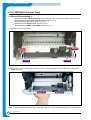
6.4.19 MPT(Multi Purpose Tray)
>> Before disassembling it:
* Disassemble all consumption parts (Toner cartridge, ITB unit, and OPC drum) (Refer to 6.3.3)
* Disassemble the front cover and top cover (Refer to 6.4.1)
* Disassemble the rear cover. (Refer to 6.4.3)
* Disassemble the duplex cover. (Refer to 6.4.4)
* Disassemble the SMPS & main PBA. (Refer to 6.4.7)
1) Release 4 screws (3*10 silver)
Screw
Screw
Screw
Screw
2) Release the 2 clips located underneath the machine (see photograph). Pull the MP Ass'y upward and
release the assy.
Snap -Fit
Snap -Fit
Note : it is not possible to remove the assy at this stage, take care not to put excessive strain on the cable harness.
6-44
Service Manual
Samsung Electronics
Disassembly and Reassembly
6.4.20Pick-UpAss'y
>> Before disassembling it:
*Disassemble
*Disassemble
*Disassemble
*Disassemble
*Disassemble
*Disassemble
*Disassemble
all consumable parts (Toner cartridges, ITB unit and OPC drum) (Refer to 6.3.3)
the front cover and top cover (Refer to 6.4.1)
the rear cover. (Refer to 6.4.3)
the duplex cover. (Refer to 6.4.4)
the SMPS & main PBA. (Refer to 6.4.7)
the Erase Lamp. (Refer to 6.4.14)
the Waster Toner Ass'y (Refer to 6.4.18)
1) Undo 2 screws (3*10 silver) and remove the “Pick-up Solenoid”. Then remove the plastic circlip which
retains the Pick-Up Gear and also remove the gear wheel. Release the shaft retaining bearing.
Pick-Up Solenoid
Screw
Screw
2) Remove the 3 screws (4*10 silver) in the “Pick-up Ass’y”
Screw
Pick-Up Ass’y
Screw
Screw
Traninung Manual
Samsung Electronics
6-45
Disassembly and Reassembly
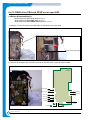
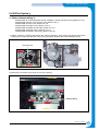
3) Remove the 3*8 black screw retaining the Guide Pick-Up plate. Using a small flat bladed screwdriver or
similar tool force the brass ground plate off the retaining lugs and bend it upward slightly. Release the
Eraser Lamp harness and paper Empty Sensor harness, these pass between the main engine frame and
base frame and cannot be removed.
Guide Pick-Up Plate
Ground Feed
Eraser Lamp Harness
Screw
4) Remove the “ACTUATOR-EMPY (JC72-00465A)” sensor arm and then take out the “Pick-up Ass’y” by
lifting the right hand side and sliding the shaft from the frame.
6-46
Traninung Manual
Samsung Electronics
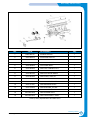
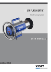
Disassembly and Reassembly
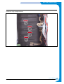
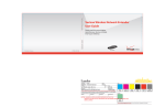
No.
Code
Description
Qt'y
1
6003-000119
SCREW-TAPTITE
1
2
JC33-00007A
SOLENOID-PICK UP
1
3
JC61-00482A
SPRING ETC-PICK UP
1
4
JC70-00359A
IPR-GROUND FEED
1
5
JC70-00360A
IPR-GUIDE INPUT
1
6
JC72-00463A
PMO-CAP CONNECTOR L
1
7
JC72-00465A
PMO CAP CONNECTOR U
1
8
JC72-00719A
PMO-ACTUATOR EMPTY
1
9
JC72-00729A
PMO-SHAFT PICK UP
1
10
JC72-01076A
PMO-GUIDE PAPER
1
11
JC72-01218A
PMO-HOLDER ERASER
1
12
JC72-41191A
PMO-BEARING SHAFT
1
13
JC72-41364A
PMO-BUSHING_P/U,MP
1
14
JC73-00149A
RPR-RUBBER PICK UP
2
15
MLC500-5538
PBA-ERASER ASS'Y
1
16
MLC500-5542
PBA-PAPER EMPTY ASS'Y
1
< Pick-Up Ass'y ExplodedView and Parts List >
Traninung Manual
Samsung Electronics
6-47