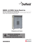
1
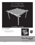
REV.00 2014 E USEANDMAINTENANCEMANUAL TSBgas63x114 Category:II2H3+ Constructiontype:B21 Useandmaintenancemanual NOTE: This Manual contains important safety and installation‐operation instructions. Require all operators to read this manual thoroughly before installing, operating or servicing this equipment. WARNING: Improper installation, adjustment, alteration, service or maintenance can cause properly damage, injury or death. Read the installation, operating and maintenance instructions thoroughly before WARNING: This appliance is not intended for use by young children or infirm persons unless they have been adequately supervised by a responsible person to ensure that they can use the appliance safely. Your children should be supervised to ensure that they do not play with the appliance. DANGER! Do not work around conveyor belt with long hair, loose clothing, or dangling jewelry. Getting caught in the belt could result in serious injury. DANGER! FOR YOUR SAFETY, do not store or use gasoline or other flammable vapors or liquids in the vicinity of this or any other appliance. DANGER! Do not spray aerosols in the vicinity of this appliance while it is in operation. DANGER! If the power supply cord appears to be damaged, do not attempt to operate the unit. Contact a service agent or qualified electrician to repair! DANGER! Do not use parchment paper when placing food product through the toaster! Use of such materials may cause a fire and should never be placed in the toaster. - Obtain from your local gas provider and pot in a prominent location instructions to be followed in the even gas odors are detected. ‐ It is required that the oven be placed under a ventilation hood to provide for adequate air supply and ventilation. ‐ Minimum clearances must be maintained from all walls and combustible materials. See “spacing instruction” for more information ‐ Keep the oven free and clear of combustible material ‐ Adequate clearance for air openings to the combustion control chamber on the right side of the oven is required.‐ Do not obstruct the ventilation holes in the back of the oven. ‐ The oven is to be operated only on the type of gas and/ or electricity shown on the specification plate. ‐ The power burner will not operate and gas will not flow through the burner without electrical power ‐ This manual should be retained for future use. 2 Useandmaintenancemanual INDEX CHAP.1 ‐ INTRODUCTION AND OVEN DESCRIPTION 1.1 General warnings 1.2 Technical data plate and supplementary plate 1.3 Technical information CHAP.2 ‐ GENERAL INSTRUCTIONS (for the installer) 2.1 Assembly and installation place 2.2 Gas connection 2.3 Electrical connection CHAP.3 ‐ COMMISSIONING (for the installer) 3.1 Checking the nominal thermal capacity 3.2 Checking the gas supply pressure 3.3 Conversion to other types of gas 3.4 Instructions for replacing certain components 3.5 Troubleshooting CHAP.4 – OPERATING INSTRUCTIONS (for the user) 4.1 Commissioning and using the oven CHAP.5 ‐ CLEANING AND ROUTINE MAINTENANCE 5.1 Wiring diagram 5.2 Gas circuit diagram This Oven must be operated on approved basis only Note: Do not install (these) ovens(s) in any area with an ambient temperature in excess of 95°F/ 35° C. 3 Useandmaintenancemanual CHAP.1 ‐ INTRODUCTION AND OVEN DESCRIPTION ITALFORNI Pesaro s.r.l. wishes to thank you for having chosen this oven. The tunnel ovens are part of the belt oven series, specifically designed for the automatic baking of pizza, bread, biscuits and related products. Baking can be carried out either directly on the refractory table or using baking trays or molds. These tunnel ovens may be included in any automatic production line. Improper use of the oven as well as any attempt at dismantling or modifying can lead to accidents and therefore the manufacturer ITALFORNI Pesaro s.r.l. declines all responsibility for any damage to persons or property caused by such tampering. For any faults encountered, contact the nearest authorized service center or the manufacturer directly. The manufacturer declines all responsibility in the following cases: ‐ Improper use of the oven by staff not suitably trained. ‐ Use not complying with the laws in force in the country of use. ‐ Lack of or incorrect routine maintenance. ‐ The use of non‐original spare parts. ‐ Total or partial failure to observe the instructions. ‐ Failure to register. The electric‐gas conveyor oven Mod. TSB GAS carries the ETL symbol issued by an authorized agency, entrusted with and responsible for assessing compliance with the essential requirements set out by the gas Directive ANSI Z83.11/ CSA 1.8 and NSF 4‐2009. The oven or the quality of the production system is subjected to periodic monitoring through inspection checks in order to ensure their conformity with the type of certificate as stated in the above Directive. The appliance must be installed in accordance with the local code in force governing the installation of gas‐ electric appliances for collective use, with the accessories and the adaptations required by the country of use as described in the use and maintenance manuals printed in the original and official languages of the different countries. More precisely, the oven must be installed on a suitable stand or sufficiently solid surface which is perfectly horizontal in a room with sufficient ventilation and must be used by trained staff only. The oven must be placed under a suitable extractor hood in order to divert the cooking vapors and combustion fumes outdoors. The oven is equipped with an atmospheric burner under the refractory tiles covering the conveyor belt. The cooking temperature can be programmed by two digital displays on the control panel. After having reached the set temperature, the burner will perform on and off cycles to maintain that temperature. If the burner does not light, a red blockage warning light will switch on and ignition can be restarted by pressing the button. In case of excessive or irregular overheating of the cooking chamber, a thermostat with automatic re‐enabling is triggered; in order to signal the anomaly, on the control panel the “over temperature” warning light comes on. 4 Useandmaintenancemanual 1.1 General warnings Read this booklet carefully as it provides directions on safety for the oven use and maintenance. The purpose of this manual is to inform operators of the rules and essential criteria for guaranteeing their safety and for prolonging the working life of the oven. Before the oven is put into service this manual must be read by all staff authorized to work on it. This instruction booklet must be kept with the oven for future reference. If the oven is sold or transferred, make sure that the booklet accompanies it every time, so that the new user can be informed of its operation and the safety warnings. It is to be kept in a place which is safe, dry and can be quickly located whenever it needs to be referred to. If it deteriorates or is lost, request a replacement copy from your nearest service center. The product is carefully packed in a sturdy wooden crate with nylon bubble packing to protect it from knocks and humidity during transportation and is consigned to the forwarder in the best possible condition. However we would advise that you check the packaging upon delivery, for evidence of any signs of damage. Should damage be found it must be noted on the delivery receipt to be signed by the driver. On unpacking the appliance, check for any signs of concealed damage. In the event of any damage do not attempt to use the appliance. Contact your nearest service center. Put the appliance into service in accordance with the governing local codes. These instructions are only valid for the category II2H3+ tunnel oven model. This oven is intended for the following type of use: cooking pizza and similar food products. It must not be used for other purposes; any other use is considered improper. The appliance is intended for collective and professional use and must be operated by staff trained in its use. Servicing, conversion to other types of gas, installation and inspection for proper working must only be performed by qualified persons. Each time a part is replaced or a component adjusted, make sure that it is sealed with paint to discourage any tampering. For all repairs, contact an authorized service center and always insist on original spare parts. The following symbol denotes “hot surface”. Avoid all direct contact with such surfaces. 5 Useandmaintenancemanual When the appliance has reached the end of its working life, all its parts and components must be disposed of separately; divide each type of material forming the oven, e.g. stainless steel parts, thermal insulation in ceramic fiber, refractory tiles, cables and electric devices. The disposal of such materials is regulated by law dispositions and EU Directives and may involve penalties in case of intentional conduct that may cause harm to the environment and to people. When using cleaning solutions, be sure they meet local and national health standards 1.2 Technical data plate The technical data plate (Fig. 1) is located on the “unloading” side of the oven and contains the voltage rating and all the other information necessary for installation. Fig. 1 Sample Data Plate Fig. 1 6 Useandmaintenancemanual 1.3 Technical information Table 1 Model External dimensions L x P x H Stand dimensions L x P x H Total nominal thermal capacity Electrical power rating Gas connection Appliance category Type of gas installation Electric security class Voltage supply Power lead TSB GAS 63x114 1170 x 2110 x 661 mm (46.5 x 83.1 x 26 in.) 1150 x 1130 x 622 mm (45.3 x 44.5 x 24.5 in.) G20 / G31 : 36.0 kW (122,800 BTU) 300 W ISO 7‐1, 3/4 “ II2H3+ B21 I 110V ~50/60Hz H07RN‐F 3x1.5 mm2 / 18 AWG Propane Gas G31 : 37 mbar (14.85 inWC) Gas connection nominal pressure Natural Gas G20 : 20 mbar (8.029 inWC) Propane Gas G31 : 25.7 mbar (10.3 inWC) Gas pressure at injector Natural Gas G20 : 14.5 mbar (5.82 inWC) Gas consumption calculated with calorific inferior G31: 3.218 kg/h (8.622lbs/hr) value Hi at 15° and 1013 mbar (59°F & 406 inWC) G20: 3.810 m3/h (10.21lbs/hr) G31: 2 x 230 1/100 mm (0.09 in.) Main injector diameter G20: 2 x 340 1/100 mm (0.134 in.) G31: 1 x 10 mm (0.39 in.) for Top * Primary air bushing setting 1 x 15 mm (0.59 in.) for Bottom * G20: 2 x 16 mm (0.63 in.) * Refers to page 23 for the location of each burner 7 Useandmaintenancemanual VIEWS AND OVERALL DIMENSIONS SUPPORT STAND Fig. 4 8 Useandmaintenancemanual STAND AND OVEN SECURED BY SCREW STACKING STAND AND OVEN SECURED BY SCREW 9 Useandmaintenancemanual RESTRAINED OVEN ON THE WALL CHAP.2 ‐ GENERAL INSTRUCTIONS (for the installer) 2.1 Assembly and installation place On receipt of the oven and before proceeding with installation, check that the goods supplied correspond with the order specifications and that no damage has been caused during transit; in the event of damage or missing parts, inform immediately and in full detail the forwarding agent (see paragraph 1.1). The installer must make sure that commissioning is carried out in accordance with the rules in force in the country where the oven is used. He must be in possession of the necessary professional qualifications and must follow the safety rules scrupulously. All extraordinary maintenance (any conversion to other types of gas or parts replacement) must be carried out by qualified persons authorized by the manufacturer. The oven must be installed in a well ventilated room with permanent ventilation openings which will guarantee sufficient flow of combustion air and a healthy workplace in general; the ovens are classified as type B21 and the combusted fumes must therefore be discharged outside the place where the oven is operated by means of a suitable motorized extractor hood. The oven should be positioned perfectly horizontally on the stand supplied or on a sufficiently solid and horizontal structure, placed on four base feet, at a distance of no less than 150mm (6 in.) from the rear wall and 1000 mm (40 in.) from the loading and unloading sides; the oven must not be located near flammable walls and is not suitable for installation in tandem formation. For installation and the minimum ventilation diameters refer to the national laws and directions in force. Be particularly careful to make sure that the volume of air needed for combustion is in no way obstructed by objects placed under or around the appliance, in particular the side holes and slits. 10 Useandmaintenancemanual RESTRAINT REQUIREMENT – GAS OVEN(S) ON CASTERS, U.S. 1. The installation shall be made with a gas connector that complies with the Standard for Connectors for Movable Gas Appliances, ANSI Z21.69 latest version, and a quick disconnect device that complies with the Standard for Quick Disconnect Devices for Use With Gas Fuel, ANSI Z21.41 latest version. IN CANADA: The installation shall be made with gas connectors that comply with Canadian Code CSA 6.16 latest version and quick disconnects complying to Canadian Code CSA 6.9 latest version. In the absence of local codes, with the national Fuel Gas Code, ANSI Z223.1/NFPA 54 or the Natural Gas and Propane Installation Code, CSA B149.1, as applicable. 2. The installation of the restraint must limit the movement of the oven(s) without depending on the connector, then quick disconnect device or its associated piping to limit the oven movement. 3. If the restraint must be disconnected during maintenance or cleaning, it must be reconnected after the oven has been returned to its originally installed position. NOTE: Installation point is the same for single and double stack oven(s). When moving this appliance, make sure to disconnect all plugins/ outlets, then reconnect upon placement in new location. Key: C = Extractor hood Installation Fig. 5 Typical installation shown 2.2 Gas connection F R V 11 = Chimney = Gas Valve On/ Off = Interlocked hood cut off valve (optional) Useandmaintenancemanual Before installation, make sure that the oven is set up for the type of gas available. Otherwise, see the paragraph “Conversion to other types of gas” or contact the manufacturer's technical service dept. The connection to the gas supply must be performed conforming to the specific installation rules by means of an approved rigid or flexible pipe, with diameters in proportion to the appliance power rating and to the length of travel. Make sure that the pipe does not pass near the hot areas and that it is not twisted or stretched. Between the gas supply and the oven, fit a type approved shutoff cock in a position that will allow easy maneuverability for opening and closing. Once the appliance is installed, carry out a leak test on the whole gas circuit, using a leak searching spray or other non‐corrosive foaming substance (do not use naked flames for this operation). The Appliance must be isolated from the gas supply piping system by closing its individual manual shutoff valve during any testing of the gas suppy piping system at test pressures equal to or less than ½ PSI (3.5 KPA) The oven is equipped with a 3/4“ gas connector. 2.3 Electrical connection It is essential for the appliance to be properly grounded in accordance with local codes, or in the absence of local codes, with the National Electrical Code, ANSI/NFPA 70, or the Canadian Electrical Code, CSAC22.2, as applicable. CHAP.3 ‐ COMMISSIONING (for the installer) 3.1 Checking the nominal thermal capacity The nominal thermal capacity must be checked by the authorized engineer or by the competent Agency, according to the information contained in this user manual. This check must be made for new installations or for conversions to other types of gas and after all extraordinary maintenance. There is no way of setting the nominal thermal capacity other than measuring the correct supply pressure and checking that the injectors used are the correct ones. The sealed components (for example with paint) must never be disturbed. The nominal thermal capacity must be checked using a counter and a chronometer. The exact volume of gas that must pass for each unit of time can be seen in the technical data table. This value must be kept within the prescribed range, with a tolerance of 5 %. If any deviation is found, a check should be made that the correct size injectors have been fitted. 3.2 Checking the gas supply pressure Before putting the oven into service, a check must be made to see whether it is suitable for the family and type of gas available, as stated on the technical data plate. If it is not, see the paragraph “Conversion to other types of gas”. 12 Useandmaintenancemanual The gas supply pressure is measured, with the appliance in operation, using a pressure gage for liquids (for example a “U“ type pressure gage with a minimum 0.1 mbar resolution). To carry out this check, access the gas valve by removing the right side panel from the oven; then, using flexible hoses, connect the pressure gage “E“ to the pressure inlet “V“ and to the pressure outlet “X“ of the gas valve after removing the relative screws (see Fig 6).Measure the inlet pressure: if this is not within the range of values shown in table 2, the oven must under no circumstances be put into operation. The gas supply agency must be informed. **NOTE** When converting to LPG, Softlight regulator “Y” must be set to “C” Position. E S T V X Gas outlet Y Fig. 6 Key: E = U-Type pressure gage- Manometer S = Pressure regulator screw cap T = Pressure regulator screw R = Pressure regulator V = Inlet gas pressure plug X = Outlet gas pressure plug Y = Soft light regulator Table 2 Inlet gas pressure (mbar) Inlet gas pressure (inch H2O column) Type of gas Normal Minimum Maximum Normal Minium Maximum Natural gas G20 20 17 25 8.02 6.82 10.03 Liquid gas G30/G31 30/37 20/25 35/45 12.04/14.85 8.02/10.03 14.05/18.06 The outlet pressure must be checked and, if necessary, corrected using the screw “T “ underneath the cap “S ”. Follow the instructions in table 3. Pre ssio H2O ne mm 1100 1000 900 800 700 600 500 400 300 13 Useandmaintenancemanual Table 3 Outlet Outlet pressure Type of gas pressure Procedure to be followed (inch H2O (mbar) column) Natural Gas 14.5 5.82 Adjust the “T” screw until the value shown to the side is reached. G20 Liquid Gas Exclude the pressure regulator by tightening “T” screw fully and 25.7 10.3 G30/G31 check that the pressure value on the side is reached. After having measured the inlet pressure and adjusted the outlet pressure, switch the oven off, close the upstream gas cock, remove the pressure gage hoses from the pressure plugs. Refit the sealing screws on the pressure inlet and outlet, tighten the regulator cover screw and seal it with paint to discourage any tampering. The Appliance and its individual shut off valve must be disconnected from the gas supply piping system during any pressure testing of that system at test pressures in excess of ½ PSI (3.5 KPA). The Appliance must be isolated from the gas supply piping system by closing its individual manual shutoff valve during any testing of the gas suppy piping system at test pressures equal to or less than ½ PSI (3.5 KPA) 3.3 Conversion to other types of gas Gas spare parts are supplied with the oven; if any spare parts are needed, contact the manufacturer’s technical service dept. Conversion must be carried out by a qualified engineer. Referring to the technical data in table 4, replace the two main injectors and the primary air adjustment on the two brass bushings. Then adjust the outlet pressure from the valve by following the procedure described in the preceding paragraph. **NOTE** When converting to LPG, Softlight regulator “Y” mustbe set to “C” Position (see Fig.6) and the air shutters set as indicate in the table below (see Fig7). WARNING ‐ Carry out this operation only after having closed the gas shutoff cock located upstream of the oven and having disconnected the oven electrical power supply. Check that the diameter of the injector is stamped on it in 1/100 of a mm. Perform the following operations in series: To gain access to the devices to adjust and replace, remove the side oven panel (on the control panel side) after removing the four screws and disconnecting the electrical connections to the cooling fan. With a suitable tool, undo and replace the two injectors “U“ with the correct ones for the gas supply. Undo the screws and regulate the air bushings “B“ to the correct distance H, according to the settings in tables and Fig. 7 . Then tighten the screw and seal it with paint. Refit the front oven panel by proceeding in reverse order. 14 Useandmaintenancemanual Fig. 7 Key: B = Primary air bushing U = Injector Gas G31 Injector diameter 2 x 230 1/100 mm (0.09in.) Distance “H” 10mm (0.39in.) for Top * 15mm (0.59in.) for Bottom* 16mm (0.63in.) G20 2 x 340 1/100 mm (0.134in.) * Refers to page 23 for the location of each burner WARNING ‐ After each conversion to new gas, always: : Apply an indelible sticker on the plate bearing the data of the new installation. Proceed with the appropriate gas circuit leakage tests. Check operation by controlling: Regular ignition of the burner branches, the stability and appearance of the flames. That the flame does not go out with the burner cold and does not return with the burner hot, meaning that the primary air is properly adjusted. 3.4 Instructions for replacing some components WARNING ‐ Carry out this operation only after closing the gas shutoff cock located upstream of the oven and disconnecting the oven electrical power supply. Replacements must be carried out by an authorized and professionally trained installer A) Gas solenoid valve Remove the side panel on the control panel side, removing the four screws. Undo the electric connections on the gas solenoid valve and on the electric control unit. Undo the inlet and outlet connections on the gas valve and remove the inlet and outlet gas pipes. Disconnect the electric control unit from the valve contacts and replace it. Refit the various parts in reverse order. 15 Useandmaintenancemanual B) Electric components of the control panel Remove the outside panel of the board by unscrewing the four screws. Each component can be replaced by disconnecting the respective wiring and then rewiring them in the same order. Attention! To replace the safety thermostat and the pyrometer, pay attention to the capillaries and bulbs which must be placed on the specific seats of the combustion chamber. C) Burner and ignition and detection plugs. Remove the side panel on the control panel side, removing the four screws. Remove the inside panel by removing the screws and gain access to the burner compartment. Unscrew the fittings which engage the pipes near the burner. Undo the electric connections on the gas solenoid valve and on the electric control unit. Disconnect the gas pipe from the front of the oven and remove it. Unscrew the burner from its seat by removing the middle screw. Carefully extract the burner from the compartment it is inserted in. Undo the wiring of the electrodes on both sides of the burner. Attention: one of the two pairs of plugs consists of an ignition plug and a flame detection plug; do not swap their wiring. Replace faulty components. Refit the various parts in reverse order. D) Refractory tiles Refractory tiles can be removed and replaced if broken or damaged, by taking out the four rivets (two of each side) and applying new ones. Note: pay attention when replacing the gas pipes or pipe fittings: conical head mechanical couplings or appropriate gas sealant guarantee the tightness of the circuit; please refer to the gas circuit diagram at the end of this manual. 3.5 Troubleshooting A) The control panel does not switch on. Possible causes: Power missing. Wires detached. B) The burner does not switch on, it remains blocked or switches off. Possible causes: The ignition plug is not secured properly, is in the wrong position or the wire is damaged. Power cable polarity is swapped. Swap neutral and phase by turning the plug around. The gas valve is faulty. Insufficient gas pressure, or air still needs to be released from the circuit. The gas pressure regulator on the valve is not set properly. The gas injectors are clogged. The burner flame outlets are clogged The work pyrometer is faulty. Wires detached. C) Incorrect temperature adjustment. Possible causes: The work pyrometer is faulty or the probe is out of place. The electronic temperature programming control unit is faulty. 16 Useandmaintenancemanual Ignition and flame sensor electrodes SEZ. A-A Fig. 8 SEZ. B-B A A B B Key: A = Ignition electrode B = Burner R = Flame sensor electrode 17 Useandmaintenancemanual CHAP.4 – OPERATING INSTRUCTIONS (for the user) ATTENTION: This gas oven is intended for commercial use. It must only be used by trained personnel. The customer is only responsible for its correct use and regular cleaning. All installation, commissioning and maintenance operations must be carried out by the manufacturer's authorized installers, in compliance with current national codes & regulations. We recommend having the oven checked periodically by a specialized technician to keep it in perfect working order. 4.1 Commissioning Before commissioning the oven, clean it thoroughly to remove manufacturing grease. Check that air flow to the burner is not obstructed and that the ventilation of the room in general is good. Make sure that the extractor hood and chimney pipe work properly. Monitor the oven while it is working. Pay attention to hot parts and moving parts. Do not obstruct any of the oven loading or unloading bulkheads. A minimum height of the bulkheads from the tiles has been established to make sure that combustion fumes are exhausted correctly while the burner is running. To keep the tiles and conveyor chain from overheating, activate the belt before starting the burner. Close the upstream gas shutoff cock and disconnect power at the end of use. 18 Useandmaintenancemanual Fig. 9 6 5 7 4 8 3 2 1 Key: 1 = 2 = 3 = 4 = 5 = 6 = 7 = 8 = 9 = Main switch Belt switch Safety thermostat warning light Burner gas restart button Burner/belt start button Belt speed setting display Top heat element temperature setting display Bottom heat element temperature setting display Emergency switch 9 Ignition (Fig. 9) Open the gas cutoff cock upstream the oven and connect power. Turn the main switch “1“ to the on position (1). Turn the belt switch “2“ to the on position. Set the belt speed display “6“ at the desired speed. Set the cooking temperature on the digital displays “ 7‐8 “ by pressing + or ‐. Temperature can be set as high as 450 °C (850 °F) . Press the green start button “5“ which starts the belt moving and switches the burner on. Burner ignition can be checked through the inspection window and the ventilation slits on the side panel opposite the board; the flame can also be viewed through the sides of the worktable, at the edges of the refractory tiles. If gas is missing, the burner blocks and the red warning light on the button “4" switches on. Press the button to restart the ignition procedure. If the burner remains blocked, swap the polarity of the electric plug. If the problem persists, contact the manufacturer's technical service. If the warning light “3“ switches on, it means that the cooking compartment is too hot and the work thermostat connected to the digital control unit does not detect the temperature properly. In this case the safety thermostat has triggered. 19 Useandmaintenancemanual Switching oven off Close the gas shutoff cock upstream of the oven. Set the cooking temperature on the digital displays “7‐8“ lower than room temperature. When work is over, turn the main switch “1“ to the off position (0) and disconnect power. Safety devices The oven is equipped with an automatic reset safety thermostat which triggers if the cooking chamber is too hot; the warning light “OVER TEMPERATURE” on the control panel switches on; in this case contact technical service to resolve the problem. The control panel has a red emergency switch “9“ which is easy to reach in case of an emergency. Press it to fully stop the oven. In case of overcurrent or short circuits, the electric system is protected by 6 A and 2 A fuses. Flame control The burner branches have two flame detection electrodes connected to two independent control units. Gas flow is interrupted if the flame goes out on one of the two electrodes. Residual risks Some parts of the oven, the two ash pans and the worktable sides, reach high temperatures, including the parts marked with the symbol on page 6. Do not touch these surfaces. If they need to be cleaned, do so after the appliance has cooled down. The oven has some moving parts such as the conveyor belt and relative gears. Do not bring your hands or work tools close to the tiles in the area where they change direction (especially on the food loading and unloading sides). **NOTE** Obtain from your local gas provider and pot in a prominent location instructions top be followed in the even gas odors are detected. 20 Useandmaintenancemanual CHAP.5 ‐ CLEANING AND ROUTINE MAINTENANCE PREVENTIVE MAINTENANCE Although this oven has been designed to be as trouble‐free as possible, periodic preventive maintenance is essential to maintain peak performance. It is necessary to keep the motors, fans, and electronic controls free of dirt, dust and debris to insure proper cooling. Overheating is detrimental to the life of all components mentioned. The periodic intervals for preventive cleaning may very greatly depending on the environment in which the oven is operating. You must discuss the need for preventive maintenance with your Authorized Service Agency to establish a proper program. If there are any questions that the service agency cannot answer, please contact Italforni Technical Service Department at (859) 488‐1025. OPERATOR MAINTENANCE To maintain maximum efficiency of the oven, it is necessary to keep it clean, all ventilation louvers on the oven must be cleaned regularly. Oven use and type of product will actually determine the frequency of cleaning. The conveyor drive should be checked during the weekly cleaning cycle to see if it has become dry. Stiffness in the conveyor system operation will DAMAGE the conveyor drive motor. If the oven fails to operate, check the circuit breaker to be sure it is turned on. Also, check the fuses on the control panel to be sure that they are good before you call the Authorized Service Agency. The na The appliance must be checked periodically. All maintenance and repair operations must be carried out by authorized and qualified personnel. CLEANING INSTRUCTIONS DAILY‐ 1. Clean exterior surfaces of the oven by wiping it down with a mild detergent and clean water, or a commercial stainless cleaner. 2. Clean crumb pans and guards by washing with a mild detergent solution and rinsing with clean water. 3. Clean the interior by sweeping up all loose particles using a high heat deck brush. If needed, you can heat up the oven to the maximum operating temperature to burn off spills prior to brushing. 4. Clean the conveyor periodically using HOT WATER while the stone is still hot and a suitable high heat brush or a mop head. USING COLD WATER WILL RESULT IS DAMAGE TO THE REFACTIR FILLETS. On exterior of oven, deposits of baked‐on splatter, oil, grease, or light discoloration may be removed with any of several commercial cleaners. Consult with your local supplier. WEEKLY 1. Inspect the conveyor for smooth operation. Grease the conveyor with the provided lubricant if neccasary 2. Vacume all dust and dirt built up from the vent holes and the cooling fan openings. NOTE: Be sure to clean and inspect the ventilation hood in accordance with the ventilation hood manufacturer’s 21 Useandmaintenancemanual 5.1 Wiring Diagram 5.2 22 Useandmaintenancemanual 5.2 Gas circuit diagram N.B. threaded couplings are secured with sealant. 23 Useandmaintenancemanual FORSERVICEINTHEUSACALL: +1 (859) 488-1025 ITALFORNIPesaroS.r.l. ViaDell’Industria,130 Loc.ChiusadiGinestreto 61100,Pesaro(PU) ITALY Tel:0721‐481515 Fax:0721‐482453 http:www.italforni.it email:[email protected] 24