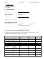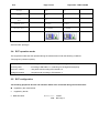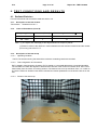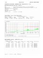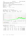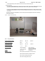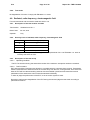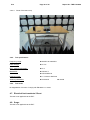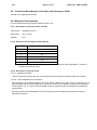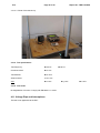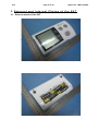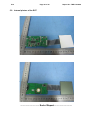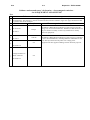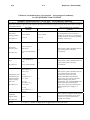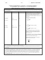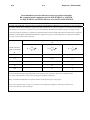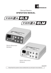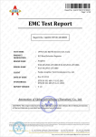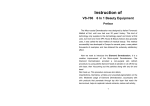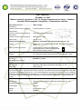
1
TEST REPORT EN 60601-1-2: 2007 Medical electrical equipment – Part 1-2: General requirements for safety – Collateral standard: Electromagnetic compatibility – Requirements and tests Report Reference No. .................... : TRE11120098 Compiled by ( position+printed name+signature) . : File administrators Vivi Zhou ..................................................... ( position+printed name+signature) . : Technique principal Sam Wang ..................................................... Approved by ( position+printed name+signature) . : Manager Tony Jiang ..................................................... Date of issue .................................... : Jan. 09, 2012 Testing Laboratory Name.............. : Shenzhen Huatongwei International Inspection Co., Ltd. Address ............................................ : Testing location/ procedure.............. : Keji S, 12th, Road, Hi-tech Industrial Park, Shenzhen, Guangdong, China Full application of Harmonised standards Partial application of Harmonised standards Other standard testing methods Applicant’s name ........................... : Ningbo Ourui New Material Technology Development Co.,Ltd. Address ............................................ : No. 9 Xiahengdai Road Lanjiang Street, Yuyao, Zhejiang, China Test specification: Standard........................................... : EN 60601-1-2: 2007 Non-standard test method…………..: / Supervised by Test Report Form No. .................... : HTWEMCCE_1A TRF Originator ................................. : Shenzhen Huatongwei International Inspection Co., Ltd. Master TRF ...................................... : Dated 2006-06 Shenzhen Huatongwei International Inspection Co., Ltd. All rights reserved. This publication may be reproduced in whole or in part for non-commercial purposes as long as the Shenzhen Huatongwei International Inspection Co., Ltd. is acknowledged as copyright owner and source of the material. Shenzhen Huatongwei International Inspection Co., Ltd. takes no responsibility for and will not assume liability for damages resulting from the reader's interpretation of the reproduced material due to its placement and context. Test item description..................... : Blood Pressure Monitor (Upper arm type) Manufacturer .................................... : Ningbo Ourui New Material Technology Development Co.,Ltd. Model/Type reference ...................... : ORA211 Listed models ................................... : ORA210 Ratings ............................................. : DC 6V, 500mA, 3W Result ............................................... : Positive V1.0 Page 2 of 24 Report No.: TRE11120098 EMC -- T E S T R E P O R T Test Report No. : TRE11120098 Jan. 09, 2012 Date of issue ______________________________________________________________________________________________ Equipment under Test : Blood Pressure Monitor (Upper arm type) Model /Type : ORA211 Listed Model : ORA210 Applicant : Ningbo Ourui New Material Technology Development Co.,Ltd. Address : No. 9 Xiahengdai Road Lanjiang Street, Yuyao, Zhejiang, China Manufacturer : Ningbo Ourui New Material Technology Development Co.,Ltd. Address : No. 9 Xiahengdai Road Lanjiang Street, Yuyao, Zhejiang, China Test Result according to the standards on page 4: Positive The test report merely corresponds to the test sample. It is not permitted to copy extracts of these test result without the written permission of the test laboratory. V1.0 Page 3 of 24 Report No.: TRE11120098 Contents 1. TEST STANDARDS .................................................................... 4 2. SUMMARY ............................................................................... 5 2.1. 2.2. 2.3. 2.4. 2.5. 2.6. 3. 3.1. 3.2. 3.3. 3.4. 3.5. 3.6. 4. 4.1. 4.2. 4.3. 4.4. 4.5. 4.6. 4.7. 4.8. 4.9. 4.10. 4.11. 5. 5.1. 5.2. General Remarks Equipment Under Test Short description of the Equipment under Test (EUT) EUT operation mode EUT configuration Compliance criteria 5 5 5 6 6 7 TEST ENVIRONMENT ................................................................. 7 Address of the test laboratory Test Facility Environmental conditions Test Description Statement of the measurement uncertainty Equipments Used during the Test 7 7 8 9 11 12 TEST CONDITIONS AND RESULTS .............................................. 13 Radiated Emission Conducted disturbance Harmonic current Voltage Fluctuation and Flicker Electrostatic discharge Radiated, radio-frequency, electromagnetic field Electrical fast transients / Burst Surge Conducted disturbances induced by radio-frequency fields Magnetic Field Immunity Voltage Dips and Interruptions 13 17 17 17 17 19 20 20 21 21 22 EXTERNAL AND INTERNAL PHOTOS OF THE EUT ......................... 23 External photos of the EUT Internal photos of the EUT ANNEX ONE PAGES…………………………………………………………………A1---A5 23 24 V1.0 Page 4 of 24 Report No.: TRE11120098 1. TEST STANDARDS The tests were performed according to following standards: EN 60601-1-2: 2007 Medical electrical equipment – Part 1-2: General requirements for safety – Collateral standard: Electromagnetic compatibility – Requirements and tests. Remark: This EUT is ranged to the Group 1 Class B apparatus according to the standard of EN 55011: 2009 clause 5.2 V1.0 Page 5 of 24 Report No.: TRE11120098 2. SUMMARY – Specified by manufacturer O – Not specified 2.1. General Remarks Date of receipt of test sample : Dec. 27, 2011 Testing commenced on : Dec. 30, 2011 Testing concluded on : Jan. 05, 2012 2.2. Equipment Under Test Power supply system utilised Power supply voltage : o 230V / 50 Hz o 115V / 60Hz 6 V DC o 24 V DC o Other (specified in blank below) / 2.3. Short description of the Equipment under Test (EUT) The EUT is an Blood Pressure Monitor (Upper arm type), and this EUT is ranged to the Group 1 Class B apparatus according to the standard of EN 55011: 2009 clause 5.2. Blood Pressure Monitor (Upper arm type) differences in Table Model Name Measurement methods Blood pressure measuring range Pulse measurement range Pressure accuracy Pulse accuracy Inflatable Pressure detection Memory Power supply Time ORA211 ORA210 Oscillometric Yes Yes 30-280mmHG Yes Yes Yes Yes Yes Yes Yes Yes Yes Yes Yes Yes 2*90 2*90 6V 4*AA 6V 4*AA Yes Yes 40-195 pulse/min +/-3mmHG +/-5% Micro pump automatic inflatable Semiconductor V1.0 Page 6 of 24 Report No.: TRE11120098 Average Yes Yes Voice Yes No Blood partition Tips Yes Yes Armband size 22-32cm 22-32cm Display Size 57.5*58mm 57.5*58mm Serial number: prototype 2.4. EUT operation mode The equipment under test was operated during the measurement under the following conditions: Test program (customer specific) Emissions tests……….….: According to EN 60601-1-2, searching for the highest disturbance. Immunity tests …………..: According to EN 60601-1-2, searching for the highest susceptivity. Harmonic current………… : Not performed according to EN 61000-3-2. Voltage fluctuation………. : Not performed according to EN 61000-3-3. 2.5. EUT configuration The following peripheral devices and interface cables were connected during the measurement: - supplied by the manufacturer o - supplied by the lab o NIBP Simulator Manufacturer : FLUKE M/N : BP Pump 2 V1.0 Page 7 of 24 Report No.: TRE11120098 2.6. Compliance criteria Under the test conditions specified in 6.2.1.10 of EN 60601-1-2: 2007, the equipment of system shall be able to provide the essential performance and remain safe. The following degradations associated with essential performance and safety shall not be allowed: - component failures; - changes in programmable parameters; - reset to factory defaults (manufacturer’s presets); - change of operating mode; - false alarms; - cessation or interruption of any intended operation, even if accompanied by an alarm; - initiation of any unintended operation, including unintended or uncontrolled motion, even if accompanied by an alarm - error of a displayed numerical value sufficiently large to affect diagnosis or treatment; - noise on a waveform in which the noise would interfere with diagnosis, treatment or monitoring; - artifact or distortion in an image in which the artifact would interfere with diagnosis, treatment or monitoring; - failure of automatic diagnosis or treatment equipment and systems to diagnose or treat, even if accompanied by an alarm. For equipment and systems with multiple functions, the criteria apply to each function, parameter and channel. The equipment or system may exhibit degradation of performance (e.g. deviation from manufacturer’s specifications) that does not affect essential performance or safety. 3. TEST ENVIRONMENT 3.1. Address of the test laboratory Shenzhen Huatongwei International Inspection Co., Ltd. Keji S, 12th, Road, Hi-tech Industrial Park, Shenzhen, Guangdong, China Tel: 86-755-26715686 Fax: 86-755-26748089 3.2. Test Facility The test facility is recognized, certified, or accredited by the following organizations: CNAS-Lab Code: L1225 Shenzhen Huatongwei International Inspection Co., Ltd. has been assessed and proved to be in compliance with CNAS-CL01 Accreditation Criteria for Testing and Calibration Laboratories (identical to ISO/IEC 17025: 2005 General Requirements) for the Competence of Testing and Calibration Laboratories, Date of Registration: Mar. 30, 2009. Valid time is until Mar. 29, 2012. A2LA-Lab Cert. No. 2243.01 Shenzhen Huatongwei International Inspection Co., Ltd. EMC Laboratory has been accredited by A2LA for technical competence in the field of electrical testing, and proved to be in compliance with ISO/IEC 17025: 2005 General Requirements for the Competence of Testing and Calibration Laboratories and any additional program requirements in the identified field of testing. Valid time is until Sep. 30, 2013. FCC-Registration No.: 662850 Shenzhen Huatongwei International Inspection Co., Ltd. EMC Laboratory has been registered and fully described in a report filed with the FCC (Federal Communications Commission). The acceptance letter from the FCC is maintained in our files. Registration 662850, Renewal date Jul. 01, 2009, valid time is until Jun. 30, 2012. V1.0 Page 8 of 24 Report No.: TRE11120098 IC-Registration No.: 5377A The 3m Alternate Test Site of Shenzhen Huatongwei International Inspection Co., Ltd. has been registered by Certification and Engineering Bureau of Industry Canada for the performance of radiated measurements with Registration No. 5377A on Jan. 25, 2011, valid time is until Jan. 24, 2014. ACA Shenzhen Huatongwei International Inspection Co., Ltd. EMC Laboratory can also perform testing for the Australian C-Tick mark as a result of our A2LA accreditation. NEMKO-Aut. No.: ELA125 Shenzhen Huatongwei International Inspection Co., Ltd. has been assessed the quality assurance system, the testing facilities, qualifications and testing practices of the relevant parts of the organization. The quality assurance system of the Laboratory has been validated against ISO/IEC 17025 or equivalent. The laboratory also fulfils the conditions described in Nemko Document NLA-10, the authorization is valid through Oct. 07, 2013. VCCI The 3m Semi-anechoic chamber (12.2m×7.95m×6.7m) and Shielded Room (8m×4m×3m) of Shenzhen Huatongwei International Inspection Co., Ltd. has been registered in accordance with the Regulations for Voluntary Control Measures with Registration No.: G-292. Date of Registration: Dec. 24, 2010. Valid time is until Dec. 23, 2013. Main Ports Conducted Interference Measurement of Shenzhen Huatongwei International Inspection Co., Ltd. has been registered in accordance with the Regulations for Voluntary Control Measures with Registration No.: C-2726. Date of Registration: Dec. 20, 2009. Valid time is until Dec. 19, 2012. Telecommunication Ports Conducted Interference Measurement of Shenzhen Huatongwei International Inspection Co., Ltd. has been registered in accordance with the Regulations for Voluntary Control Measures with Registration No.: T-1837. Date of Registration: May 07, 2010. Valid time is until May 06, 2013. DNV Shenzhen Huatongwei International Inspection Co., Ltd. has been found to comply with the requirements of DNV towards subcontractor of EMC and safety testing services in conjunction with the EMC and Low voltage Directives and in the voluntary field. The acceptance is based on a formal quality Audit and follow-ups according to relevant parts of ISO/IEC Guide 17025 (2005), in accordance with the requirements of the DNV Laboratory Quality Manual towards subcontractors. Valid time is until Aug. 24, 2013. 3.3. Environmental conditions During the measurement the environmental conditions were within the listed ranges: Temperature: 22-25 ° C Humidity: 40-54 % Atmospheric pressure: 950-1050mbar V1.0 Page 9 of 24 Report No.: TRE11120098 3.4. Test Description Emission Measurement Radiated Emission EN 60601-1-2: 2007 EN 55011: 2009 Conducted Disturbance EN 60601-1-2: 2007 (0.15-30MHz) EN 55011: 2009 Harmonic Current EN 60601-1-2: 2007 PASS N/A N/A EN 61000-3-2: 2006+A1: 2009+A2: 2009 Voltage Fluctuation and Flicker EN 60601-1-2: 2007 N/A EN 61000-3-3: 2008 Immunity Measurement Electrostatic Discharge EN 60601-1-2: 2007 EN 61000-4-2: 2009 RF Field Strength Susceptibility EN 60601-1-2: 2007 (80~2500MHz) EN 61000-4-3: 2006 Electrical Fast Transient/Burst Test EN 60601-1-2: 2007 Surge Test EN 60601-1-2: 2007 EN 61000-4-4: 2004+A1: 2010 EN 61000-4-5: 2006 Conducted Susceptibility Test EN 60601-1-2: 2007 EN 61000-4-6: 2009 Power Frequency Magnetic Field Susceptibility Test EN 60601-1-2: 2007 Voltage Dips and Interruptions Test EN 60601-1-2: 2007 EN 61000-4-8: 2010 EN 61000-4-11: 2004 Note: “N/A” means “not applicable”. The measurement uncertainty is not included in the test result. PASS PASS N/A N/A N/A PASS N/A V1.0 Page 10 of 24 Report No.: TRE11120098 EN 60601-1-2 Clause 5 5.1 5.1.1 5.1.2 5.1.3 5.2 5.2.1 5.2.1.1 a) b) 5.2.1.2 a) b) c) d) e) 5.2.1.3 a) b) 5.2.1.4 5.2.2 5.2.2.1 a) b) c) d) e) f) 5.2.2.2 a) Requirement + Test Result - Remark IDENTIFICATION, MARKING AND DOCUMENTS Marking on the outside of ME EQUIPMENT OR ME EQUIPMENT parts RF equipment marked with symbol IEC 60417-5140 Equipment for which the connector testing exemption is used marked with symbol IEC 60417-5134 Equipment specified for use only in shielded location has appropriate marking ACCOMPANYING DOCUMENTS Instructions for use All equipment and systems: A statements that medical electrical equipment Please refer to User manual needs special precautions regarding EMC and needs to be installed according to EMC information A statement that RF communications equipment Please refer to User manual can effect medical electrical equipment Equipment for which the connector testing exemption is used: A reproduction of the ESD warning symbol (IEC 60417-5134) A warning that pins of connectors marked with the warning symbol shall not be touched and connections shall not be made without special precautions A specification of precautionary procedures A recommendation that all staff receive explanation and training in ESD procedures A specification of the minimum contents of ESD precautions procedure training For equipment and systems without a manual sensitivity adjustment and for which the manufacturer specifies a minimum amplitude or signal: The minimum amplitude or value of signal Please refer to User manual A warning that operation of the equipment below Please refer to User manual that value may cause incorrect results Requirements applicable to TYPE A PROFESSIONAL SYSTEMS TECHNICAL DESCRIPTION All equipment and systems: List of cables and accessories Please refer to User manual A warning that other cables and accessories may Please refer to User manual affect EMC performance Table 1, modified as appropriate Please refer to User manual A warning regarding stacking and location close to other equipment A justification for each immunity compliance level below 60601 test level Table 2, completed as appropriate Equipment not specified for use only in shielded location Table 3 and Table 5 shall be used for LIFESUPPORTING , Table 4 and Table 6 shall be used are not LIFE-SUPPORTING , selected and completed as appropriate ME EQUIPMENT or ME SYSTEM shall be replaced with the MODEL OR TYPE REFERENCE of the ME EQUIPMENT or SYSTEM Verdict PASS N/A N/A N/A N/A PASS PASS PASS PASS PASS N/A N/A N/A N/A N/A N/A PASS PASS PASS N/A PASS PASS PASS PASS PASS N/A N/A N/A PASS PASS PASS V1.0 Page 11 of 24 b) c) d) e) 5.2.2.3 a) b) c) d) 5.2.2.4 5.2.2.5 5.2.2.6 5.2.2.7 5.2.2.8 5.2.2.9 5.2.2.10 6 Report No.: TRE11120098 Table 3or Table 4,as applicable shall be filled in with the IMMUNITY COMPLIMENT LEVEL in accordance with the requirements of 5.2.2 and 6.2 The expressions of Table 3 Table 4 and Table 5 Table 6,as applicable, shall be calculated,the results substituted in place of the COMPLIANCE LEVELS for IEC61000-4-6and IEC61000-4-3 test Table 5 and Table 6,as applicable,shall be completed by calculating the distance corresponding to each entry in columns 2 through 5 in Table5 or in columns 2 through 4 in Table 6 If,according to 6.2 or the scope of the EMC basic standard not apply to,the corresponding entries shall state “not applicable” Equipment specified for use only in shielded location A warning that equipment should be used only in the specified type of shielded location Tables modified if disturbance allowance according in 6.1.1.1 d) is used A specification of allowed emission of other equipment located within the shielded location Table 7 shall be used for LIFE-SUPPORTING, Table 8 shall be used are not LIFE-SUPPORTING Equipment that intentionally apply RF energy Equipment that intentionally receive RF energy Equipment that includes RF transmitters Requirements of cables and accessories Please refer to User manual Requirements applicable to large permanently installed equipment and systems Requirements applicable to equipment that has no essential performance Requirements applicable to TYPE A PROFESSIONAL SYSTEMS ELECTROMAGNETIC COMPATIBILITY (se appended table) PASS PASS PASS PASS N/A N/A N/A N/A N/A N/A N/A N/A PASS N/A N/A N/A 3.5. Statement of the measurement uncertainty The data and results referenced in this document are true and accurate. The reader is cautioned that there may be errors within the calibration limits of the equipment and facilities. The measurement uncertainty was calculated for all measurements listed in this test report acc. to CISPR 16 - 4 „Specification for radio disturbance and immunity measuring apparatus and methods – Part 4: Uncertainty in EMC Measurements“ and is documented in the Shenzhen Huatongwei International Inspection Co., Ltd quality system acc. to DIN EN ISO/IEC 17025. Furthermore, component and process variability of devices similar to that tested may result in additional deviation. The manufacturer has the sole responsibility of continued compliance of the device. Hereafter the best measurement capability for Shenzhen Huatongwei laboratory is reported: Test Radiated Emission Range 30~1000MHz Measurement Uncertainty 4.65dB Notes (1) (1) This uncertainty represents an expanded uncertainty expressed at approximately the 95% confidence level using a coverage factor of k=2. V1.0 Page 12 of 24 Report No.: TRE11120098 3.6. Equipments Used during the Test Radiated Emission Item Test Equipment Manufacturer Model No. Serial No. 1 ULTRA-BROADBAND ANTENNA ROHDE & SCHWARZ HL562 100015 2011/05 2 EMI TEST RECEIVER ROHDE & SCHWARZ ESI 26 100009 2011/10 3 RF TEST PANEL ROHDE & SCHWARZ TS / RSP 335015/ 0017 2011/10 4 TURNTABLE ETS 2088 2149 2011/10 5 ANTENNA MAST ETS 2075 2346 2011/10 6 EMI SOFTWARE ROHDE & SCHWARZ ESK1 N/A 2011/10 TEST Last Cal. Electrostatic Discharge Item Test Equipment Manufacturer Model No. Serial No. Last Cal. 1 ESD 30 System EM TEST ESD 30C V0511100210 2011/10 RF Field Strength Susceptibility Item Test Equipment Manufacturer Model No. Serial No. Last Cal. 1 SIGNAL GENERATOR IFR 2032 203002/100 2011/10 2 AMPLIFIER AR 150W1000 301584 2011/10 3 DUAL DIRECTIONAL COUPLER AR DC6080 301508 2011/10 4 POWER HEAD AR PH2000 301193 2011/10 5 POWER METER AR PM2002 302799 2011/10 6 TRANSMITTING AERIAL AR AT1080 28570 2011/10 7 POWER AMPLIFIER AR 25S1G4A 0325511 2011/10 8 DUAL DIRECTIONAL COUPLER AR DC7144A 0325100 2011/10 9 TRANSMITTING AERIAL AR AT4002A 0324848 2011/10 Power Frequency Magnetic Field Susceptibility Item Test Equipment Manufacturer Model No. Serial No. Last Cal. 1 ULTRA COMPACT SIMULATOR EM TEST UCS500M6 202304/060 2011/10 2 MOTOR DRIVEN VOLTAGE TRANSFORMER EM TEST MV2616 302205 2011/10 3 CURRENT TRANSFORMER EM TEST MC2630 302389 2011/10 4 MAGNETIC COIL EM TEST MS100 0010230A 2011/10 V1.0 Page 13 of 24 Report No.: TRE11120098 4. TEST CONDITIONS AND RESULTS 4.1. Radiated Emission For test instruments and accessories used see section 3.6. 4.1.1. Description of the test location Test location: 4.1.2. Shielded room No. 4 Limits of disturbance (Class B) Frequency (MHz) Distance (Meters) Field Strengths Limits (dBμV/m) 30 ~ 230 3 40 230 ~ 1000 3 47 Note: (1) The tighter limit shall apply at the edge between two frequency bands. (2) Distance refers to the distance in meters between the test instrument antenna and the closest point of any part of the E.U.T. 4.1.3. Description of the test set-up 4.1.3.1. Operating Condition The EUT is turned on during the test and the maximum emanating results are recorded. 4.1.3.2. Test Configuration and Procedure EUT is tested in Semi-Anechoic Chamber. EUT is placed on a nonmetal table above a grounded turntable. The turntable can rotate 360 degrees to determine the azimuth of the maximum emission level. EUT is set 3 meters away from the center of receiving antenna. The antenna can move up and down from 1 to 4 meter to find out the maximum emission level. Both horizontal and vertical polarizations of the antenna are set on the test. 4.1.3.3. Photos of the test set-up V1.0 4.1.4. Page 14 of 24 Report No.: TRE11120098 Test result The requirements are Fulfilled Band Width: 120kHz Frequency Range: 30MHz to 1000MHz Remarks: The limits are kept. For detailed results, please see the following page(s). Margin=limit-level Level=read values+transducer Transducer=antenna factor+pre-amplifier factor+cable loss V1.0 Page 15 of 24 Report No.: TRE11120098 V1.0 Page 16 of 24 Report No.: TRE11120098 V1.0 Page 17 of 24 Report No.: TRE11120098 4.2. Conducted disturbance The test is not applicable to the EUT. 4.3. Harmonic current The test is not applicable to the EUT. 4.4. Voltage Fluctuation and Flicker The test is not applicable to the EUT. 4.5. Electrostatic discharge For test instruments and accessories used see section 3.6. 4.5.1. Description of the test location and date Test location: Shielded room No. 1 Date of test: Jan. 05, 2012 Operator: Jony 4.5.2. Severity levels of electrostatic discharge Test Voltage Test Voltage Contact Discharge (KV) Air Discharge (KV) 1 2 2 2 4 4 3 6 8 4 8 15 Level X Special Special Note: equipment and systems shall comply with the requirements of 6.2.2 of EN 60601-1-2: 2007 at immunity test levels of ± 2KV, ± 4KV and ±8KV for air discharge and ± 2KV, ± 4KV and ± 6KV for contact discharge. 4.5.3. Description of the test set-up 4.5.3.1. Operating Condition The EUT is turned on during the test and the results of the maximum susceptive results are recorded. 4.5.3.2. Test Configuration and Procedure: Air Discharge: -This test is done on a non-conductive surfaces. The round discharge tip of the Electrostatic Discharge simulator shall be approached as fast as possible then to touch the EUT. After each discharge, the simulator shall be removed from the EUT. The simulator is then re-triggered for a new single discharge and repeated 25 times for each pre-selected test point. This procedure shall be repeated until all the air discharge completed Contact Discharge: -All the procedure shall be same as air discharge, except using the acute discharge tip. The top end of the Electrostatic Discharge simulator is touch the EUT all the time when the simulator is re-triggered for V1.0 Page 18 of 24 Report No.: TRE11120098 a new single discharge and repeated 10 times for each pre-selected test point. Indirect Discharge: -The vertical coupling plane(VCP) is placed 0.1m away from EUT. The top end of Electrostatic Discharge simulator should aim at the center of one border of the VCP for at least 10 times discharge. -The top end of Electrostatic Discharge simulator should place at the point 0.1m away from EUT on the horizontal coupling plane(HCP). At least 10 times discharge should be done for every pre-selected point around EUT. Record any performance degradation of the EUT during the test and judge the test result according to performance criterion. 4.5.3.3. Photo of the test set-up 4.5.4. Test specification: Contact discharge voltage: 2 kV 4 kV 6 kV Number of discharges: 10 □ 25 Air discharge voltage: 2 kV 4 kV Number of discharges: □ 10 25 Type of discharge: Direct discharge Polarity: Indirect discharge Positive Discharge location: see photo documentation of the test set-up 8 kV Air discharge Contact discharge Contact discharge Negative all external locations accessible by hand horizontal coupling plane (HCP) vertical coupling plane (VCP) V1.0 4.5.5. Page 19 of 24 Report No.: TRE11120098 Test result No degradation of function. Comply with EN 60601-1-2: 2007. 4.6. Radiated, radio-frequency, electromagnetic field For test instruments and accessories used see section 3.6. 4.6.1. Description of the test location and date Test location: Shielded room No. 4 Date of test: Jan. 05, 2012 Operator: Jony 4.6.2. Severity levels of radiated, radio-frequency, electromagnetic field Level Field Strength (V/m) 1. 1 2. 3 3. 10 X Special Note: equipment and systems shall comply with the requirements of 6.2.3 of EN 60601-1-2: 2007 at immunity test levels of 3V/m. 4.6.3. Description of the test set-up 4.6.3.1. Operating Condition The EUT is turned on during the test and the results of the maximum susceptive results are recorded. 4.6.3.2. Test Procedure EUT and its auxiliary instrument are placed on a turntable which is 0.8 meter above ground. Transmitting antenna mounted on an antenna mast is set 3 meter away from the EUT. During the test, each of the four sides of EUT will face the transmitting antenna with the turntable cycled. Both horizontal and vertical polarization of the antenna are set on test and measured individually. In order to judge the performance of the EUT, a set of monitor system is used. Record any performance degradation of the EUT during the test and judge the test result according to performance criterion. V1.0 Page 20 of 24 Report No.: TRE11120098 4.6.3.3. Photo of the test set-up 4.6.4. Test specification: Frequency range: 80 MHz to 2500 MHz Field strength: 3 V/m EUT - antenna separation: 3m Modulation: AM: 80 % sinusoidal 2Hz Frequency step: 1 % with 3s dwell time Antenna polarisation: horizontal 4.6.5. Test result No degradation of function. Comply with EN 60601-1-2: 2007. 4.7. Electrical fast transients / Burst The test is not applicable to the EUT. 4.8. Surge The test is not applicable to the EUT. vertical V1.0 Page 21 of 24 Report No.: TRE11120098 4.9. Conducted disturbances induced by radio-frequency fields The test is not applicable to the EUT. 4.10. Magnetic Field Immunity For test instruments and accessories used see section 3.6. 4.10.1. Description of the test location and date Test location: Shielded room No. 1 Date of test: Jan. 05, 2012 Operator: Jony 4.10.2. Severity levels of magnetic field immunity Level Magnetic Field Strength (A/m) 1 1 2 3 3 10 4 30 5 100 X. Special Note: equipment and systems shall comply with the requirements of 6.2.8 of EN 60601-1-2: 2007 at immunity test levels of 3A /m. 4.10.3. Description of the test set-up 4.10.3.1. Operating Condition The EUT is turned on during the test, and the results of the maximum susceptive results are recorded. 4.10.3.2. Test Configuration and Procedure: EUT is placed on an insulating support of 0.1m high above a table of 0.8m high. There is a minimum 1m*1m ground metallic plane put on this table. EUT is put in the center of the magnetic coil then three orientations of the magnetic coil, X, Y and Z, shall be rotated in order to expose the EUT to the difference polarization magnetic field. Record any performance degradation of the EUT during the test and judge the test result according to performance criterion. V1.0 Page 22 of 24 Report No.: TRE11120098 4.10.3.3. Photo of the test set-up 4.10.4. Test specification: Test frequency: 50 Hz Continuous field: 3 A/m Test duration: 5 mins Antenna factor: 0.917 A/m Axis: x-axis 4.10.5. Test result No degradation of function. Comply with EN 60601-1-2: 2007. 4.11. Voltage Dips and Interruptions The test is not applicable to the EUT. 60 Hz y-axis z-axis V1.0 Page 23 of 24 Report No.: TRE11120098 5. External and Internal Photos of the EUT 5.1. External photos of the EUT V1.0 Page 24 of 24 Report No.: TRE11120098 5.2. Internal photos of the EUT ................................ End of Report............................... V1.0 A1 Report No.: TRE11120098 Annex of Report Manufacturer’s Declaration of the EUT (altogether 5 pages) V1.0 A2 Report No.: TRE11120098 Guidance and manufacturer´s declaration – electromagnetic emission – for all EQUIPMENT AND SYSTEMS Row 1 2 3 Guidance and manufacturer´s declaration – electromagnetic emission The ORA211 Blood Pressure Monitor (Upper arm type) is intended for use in the electromagnetic environment specified below. The customer or the user of ORA211 Blood Pressure Monitor (Upper arm type) should assure that it is used in such an environment. Emissions test Compliance Electromagnetic environment - guidance Group 1 The ORA211 Blood Pressure Monitor (Upper arm type) uses RF energy only for its internal function. Therefore, its RF emissions are very low and are not likely to cause any interference in nearby electronic equipment. RF emissions 4 EN 55011 RF emissions 5 Class B EN 55011 Harmonic emissions N/A 6 EN 61000-3-2 7 Voltage fluctuations / flicker emissions EN 61000-3-3 N/A The ORA211 Blood Pressure Monitor (Upper arm type) is suitable f or use in all establishments, including domestic establishments and those directlyconnected to the public low-voltage power supplynetwork that supplies buildings used for domestic purposes. V1.0 A3 Report No.: TRE11120098 Guidance and manufacturer's declaration – electromagnetic immunity – for all EQUIPMENT and SYSTEMS Guidance and manufacturer´s declaration – electromagnetic immunity The ORA211 Blood Pressure Monitor (Upper arm type) is intended for use in the electromagnetic environment specified below. The customer or the user of the ORA211 Blood Pressure Monitor (Upper arm type) should assure that it is used in such an environment. Electromagnetic environment EN 60601 Compliance level Immunity test guidance test level Electrostatic discharge (ESD) EN 61000-4-2 Electrostatic transient / burst ± 6 kV contact ± 6 kV contact ± 8 kV air ± 8 kV air ± 2 kV for power supply lines EN 61000-4-4 ± 1 kV for input/output lines Surge ± 1 kV differential mode EN 61000-4-5 N/A Mains power quality should be that of a typical commercial or hospital environment. N/A Mains power quality should be that of a typical commercial or hospital environment. ± 2 kV common mode < 5 % UT (>95 % dip in UT ) for 0.5 cycle Voltage dips, short 40 % UT interruptions and (60 % dip in UT ) voltage variations for 5 cycles on power supply input lines 70 % UT (30 % dip in UT ) EN 61000-4-11 for 25 cycles N/A < 5 % UT (>95 % dip in UT ) for 5 sec Power frequency (50/60 Hz) magnetic field EN 61000-4-8 NOTE 3 A/m Floors should be wood, concrete or ceramic tile. If floors are covered with synthetic material, the relative humidity should be at least 30 %. 3 A/m Mains power quality should be that of a typical commercial or hospital environment. If the user of the ORA211 Blood Pressure Monitor (Upper arm type) requires continued operation during power mains interruptions, it is recommended that the ORA211 Blood Pressure Monitor (Upper arm type) be powered from an uninterruptible power supply or a battery. Power frequency magnetic fields should be at levels characteristic of a typical location in a typical commercial or hospital environment. UT is the a. c. mains voltage prior to application of the test level. V1.0 A4 Report No.: TRE11120098 Guidance and manufacturer´s declaration – electromagnetic immunity – for EQUIPMENT and SYSTEM that are not LIFE-SUPPORTING Guidance and manufacturer´s declaration – electromagnetic immunity The ORA211 Blood Pressure Monitor (Upper arm type) is intended for use in the electromagnetic environment specified below. The customer or the user of the ORA211 Blood Pressure Monitor (Upper arm type) should assure that it is used in such an environment. Immunity test EN 60601 test level Compliance level Electromagnetic environment - guidance Portable and mobile RF communications equipment should be used no closer to any part of the ORA211 Blood Pressure Monitor (Upper arm type), including cables, than the recommended separation distance calculated from the equation applicable to the frequency of the transmitter. Conducted RF 3 Vrms EN 61000-4-6 150 kHz to 80 MHz Radiated RF 3 V/m EN 61000-4-3 80 MHz to 2.5 GHz N/A 3 V/m Recommended separation distance d =[ 3.5 ] P V1 d =[ 3.5 ] P E1 d =[ 7 ] P E1 80 MHz to 800 MHz 800 MHz to 2.5 GHz where p is the maximum output power rating of the transmitter in watts (W) according to the transmitter manufacturer and d is the recommended separation distance in metres (m).b Field strengths from fixed RF transmitters, as determined by an electromagnetic site survey,a should be less than the compliance level in each frequency range.b Interference may occur in the vicinity of equipment marked with the following symbol: NOTE 1 At 80 MHz and 800 MHz, the higher frequency range applies. NOTE 2 These guidelines may not apply in all situations. Electromagnetic is affected by absorption and reflection from structures, objects and people. a Field strengths from fixed transmitters, such as base stations for radio (cellular/cordless) telephones and land mobile radios, amateur radio, AM and FM radio broadcast and TV broadcast cannot be predicted theoretically with accuracy. To assess the electromagnetic environment due to fixed RF transmitters, an electromagnetic site survey should be considered. If the measured field strength in the location in which the ORA211 Blood Pressure Monitor (Upper arm type) is used exceeds the applicable RF compliance level above, the ORA211 Blood Pressure Monitor (Upper arm type) should be observed to verify normal operation. If abnormal performance is observed, additional measures may be necessary, such as reorienting or relocating the ORA211 Blood Pressure Monitor (Upper arm type). b Over the frequency range 150 kHz to 80 MHz, field strengths should be less than 3V/m. V1.0 A5 Report No.: TRE11120098 Recommended separation distances between portable and mobile RF communications equipment and the EQUIPMENT or SYSTEM for EQUIPMENT and SYSTEMS that are not LIFE-SUPPORTING Recommended separation distances between portable and mobile RF communications equipment and the ORA211 Blood Pressure Monitor (Upper arm type) The ORA211 Blood Pressure Monitor (Upper arm type) is intended for use in an electromagnetic environment in which radiated RF disturbances are controlled. The customer or the user of the ORA211 Blood Pressure Monitor (Upper arm type) can help prevent electromagnetic interference by maintaining a minimum distance between portable and mobile RF communications equipment (transmitters) and the ORA211 Blood Pressure Monitor (Upper arm type) as recommended below, according to the maximum output power of the communications equipment Separation distance according to frequency of transmitter m 150 kHz to 80 MHz Rated maximum output of transmitter d =[ 3.5 ] P V1 80 MHz to 800 MHz d =[ 3.5 ] P E1 800 MHz to 2.5 GHz d =[ 7 ] P E1 W 0.01 / 0.12 0.23 0.1 / 0.38 0.73 1 / 1.2 2.3 10 / 3.8 7.3 100 / 12 23 For transmitters rated at a maximum output power not listed above the recommended separation distance d in metres (m) can be estimated using the equation applicable to the frequency of the transmitter, where P is the maximum output power rating of the transmitter in watts (W) according to the transmitter manufacturer. NOTE 1 At 80 MHz and 800 MHz, the separation distance for the higher frequency range applies. NOTE 2 These guidelines may not apply in all situations. Electromagnetic propagation is affected by absorption and reflection from structures, objects and people.