1
:
C9502FEl.DOC
NC9502F.ling
Brevetti C.E.A. S.p.A.
Via del Commercio 28
36050 Sovizzo VI - ITALY
Tel. 0444-551988
Fax 0444-536241
COpy
/'1-
..3
Functional Specifications
ATM18
Order: NC9502F
C9502
1
January
30, 1996 - Canada
Connaught
Reference:
This document contains 32 pages, one page of Appenidx B and one Enclosure.
Author:
V. Maruzzo
Name
Position
Review:
A. Signorelli
Project Responsible
Approval :
D. Dal Bello
Q.A. Manager
Customer's review:
Customer's approval:
A TM18 - Functional Specifications
Signature
Date
C9502FEl.DOC
NC9 502F. 1ing
TABLE OF CONTENTS
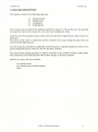
1. INTR 0 DUCTI 0 N
3
3
1.1 REFERENCES
2. G ENERAL DESC RI PTI 0 N
2.1 PROCESS DESCRIPTION
2.1.1 Process
Diagram
4
4
1-4)
(Sheets
6
2. 1.2 Mech anics Iayo u t.
10
10
2.2 COMPUTER DESCRIPTION
2.2.1 Hardware
architecture
10
2.2.2 S oftwa re arch itectu re
11
2.3 MA CHINE D ESC RIP TIO N
15
2.4 TEC HNICA L NO TE S
2.4. 1 Perform a n ces
16
16
2.4.2 Services
2.4.3 Limits
required
16
..........................................................................................................................................•.......
17
2.4 .4 Working en vi ronm en t
2.4.5 Expa nda b i/ity, in teria ce,
17
0ptio
17
ns
3. FUN CTI 0 NS
3.1 ACQUISITION S YSTEM
3.1.2 PROCESSING SySTEM
;;::::
18
18
18
3.2 TEST S
3.2.1 Station
20
TV1 Station
TV3
20
3.2.2 Sta tio n TV2
21
3.2.3 St a tion TV 4
3. 3 MECHANICS
22
23
3.3.1 Loading
23
3.3.2 Gripping
system
23
3.3.3 0 utp ut
3.3.4 Pro tecti
24
24
24
0ns
3.4 SAFETY - ERROR AND ALARM
MESSAGES
3.4.1 Safe ty
24
25
28
3.4.2 Error and alarm messages
4. INTE RFACE
4.1 A CC ESS LEVELS
28
4.1.1 Opera tor
4.1. 2 Supervisor
29
31
4.1.3 Main tenance
31
technician
5. GLOSSARY
32
APPENDIX B: Classes of Defects and Reject Priority
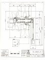
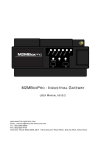
ENCLOSURE:
Enclosure1:
LAY-CONNAUGHT-13
(rev. 2)
A1M18 - Functional Specifications
2
C9502FEl.DOC
NC9502F.l
ing
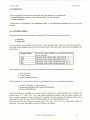
1. INTRODUCTION
This document is prepared by Brevetti C.E.A. S.p.A. in order to define functional criteria of
ATM18 machine, which must operate in line with a LTM Jupiter to inspect O.5/lml and 6ml
ampoules.
The tests required by the Customer in the User Requirement Specification [1] are subdivided
between the two machines as follows (ATM18 is placed upstream respect to LTM Jupiter):
Station
TCM
Test
I TVI-TV2
I....
T_ip
TV2TVI- TV3
Particles
bottom
Level
andon
black
particles
LTM
I Stations 1-2-3-4
Ref. U.RS. I.!1
N.A.
_
N.A.
I Micro-holes
I
N.A.
I
This document is prepared in accordance with what foreseen in I4.15 Instruction (Standard Format
of Machine Documentation) [2].
This document is produced by the System Analysis Department and approved by Quality Assurance
and then submitted to the Customer's approval, as foreseen by the Quality Plan [3].
1.1 REFERENCES
When there is a reference to another document only the number is reported into square brackets as
indicated in the following table:
NO. REF.
DOCUMENT
[1]
SPECIFICATIONS FOR BREVETTI AUTOMATIC
INSPECTION MACIDNE AND BREVETTI JUPITER LEAK
DETECTOR - dated June 26, 1995
N.A.
NC9502Z
NG9502F
I4.15
NC9502U
NN9501F
NN9501Q
[2]
[7]
ATM18
Standard
User
Format
Manual'
of SP
Machine
Documentation
SW
programs
and Parameters
L
TCM
TMConfiguration,
Jupiter
Functional
Functional
Specifications
Specifications
Quality
Plan
A TMl8 - Functional
Specifications
3
C9502FEl.DOC
NC9502F.ling
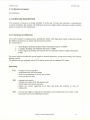
2. GENERAL DESCRIPTION
ATM18 machine is designed to be inserted in modern pharmaceutical product lines. It is installed
downstream from filling and freeze-drying lines and upstream from labelling and packaging systems.
ATM18 receives the containers by the upstream machine (TCM) by means of a "first-in first-out"
line.
The output of rejected containers occurs on standard stainless steel C.E.A. boxes; the accepted
containers are addressed to the loading table of the downstream machine (LTM Jupiter).
The ATM18 machine consists of:
Mechanical module: inserted in the production line and charged with transporting the
containers along the test path. The mechanical module has got a "double" configuration (two
modules mechanically equal and specular, but wholly independent).
Remote monitoring and control console: it handles the mechanic module management and
its interface with the production line. Furthermore it permits the user's monitoring of the
process.
2.1 PROCESS DESCRIPTION
Process control is totally automatic. Each container undergoes a series of tests performed by
telecameras. It is enough that only one of the tests results negative for the container to be rejected.
Containers are transported along the test path including the tests which are listed here below:
Station
bottom
Test
Particles
N.A. fll
Level andon
black
particlesRef. V.R.S.
The specifications of the different test stations and of the image processing method are present in
Chapter 3 (Functions) of this document.
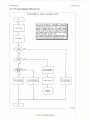
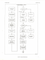
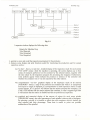
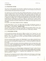
The process diagram is shown in the next pages. Sheet 1 shows the process flow chart for all
inspection stations: if inspection is enabled, the images are processed and the result is stored as an
active "reject" or "accept" flag in the shift register.
The acquired scans are processed while the machine is carrying the container to the next station. The
diagram shows from the functional point of view the main functions performed by the system during
operation. A more detailed explanation of the routines the software executes to test the various
sections of the machine is given in the Software Design Specification.
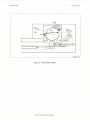
Fig. 2.1 shows the layout of the stations to which we refer in the process diagram.
A TM18 - Ftmctional Specifications
4
C9502FEl.DOC
NC9502F.ling
TV2
TV1
r!)\
accepted
C9502f21.cdr
Fig. 2.1 - Test station layout
A1M18 - Flillctional Specifications
5
C9502FE1.DOC
NC9502F.ling
2.1.1 Process Diagram (Sheets 1-4)
Process diagram - sheet 1: acquisition routine
Start
Each station assigns its "Goodlreject" flag to the
container to be inspected. If the station is disabled,
the flag always assumes the "Good" value. If the
station is enabled and it did not detect defects
beyond the tolerance allowed, the flag assumes the
"Good" value. The container is accepted if the flags
of all stations have the "Good" value at the moment
when it reaches the machine output.
N.B.:The aim of this diagram is to show the process
from a functional point of view. Actually the functions
shown here are performed by different processors.
Acquire images
Process images
No
No
No
The "accept/rejecf'
flag in set to "reject"
(
End
The "accept/reject"
flag in set to "reject"
The "accept/reject"
flag in set to "accept"
Stop the machine
)
The "accept/reject"
flag in set to "accept"
k9502pr1 cdr
ATM18 - Functional Specifications
6
C9502FEl.DOC
NC9502F.ling
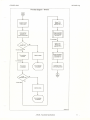
Process diagram - sheet 2
No
Container comes
from TCM
6 turret steps
Container is picked-up
by first star wheel
The container
is braked
Machine
stops
Machine
stops
1 turret steps
Container
is detected
by proximity
sensor
The spindle
is orientated
Shift register is
updated with
"container present"
No
flag
Container is inserted
into turret
Container
rotating
starts
on its axis
Station
TV1:
particles test
(see par. 3.2.1)
Image acquisition
and processing
(see sheet 1)
5 turret steps
Check
correct
operation of
rotation mechanism
Station
TV2:
particles on bottom tes
(see par. 3.2.2)
Image acquisition
and processing
(see sheet 1)
c9S02pr2.cdr
ATM18 - FlUlctional Specitications
7
C9502FE I.DOC
NC9502F.ling
Process diagram - sheet 3
Container
Station 1V3:
starts
particle test
(see par. 3.2.1)
rotating again
Check correct
Image acquisition
and processing
(see sheet 1)
operation of
rotation mechanism
3 turret steps
Station 1V4:
fill level test
No
(see par. 3.2.3)
The container
is braked
Machine
stops
Image acquisition
and processing
(see sheet 1)
1 turret steps
Error message
is displayed
The spindie
is orientated
Container
moves
to the sorti ng device
No
1 turret steps
Machine
stops
k9502pr3.cdr
ATMl8
- Functional Specifications
8
----------C9502FEl.DOC
NC9502F.ling
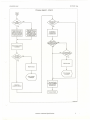
Process diagram - sheet 4
Yes
No
Reject device is not
energized. It remains
engaged to a earn
which makes it push
the container towards
Reject device is ener·
gized. It disengages
itself from the earn and
the container proceeds
to the accept device
A message is
displayed with
an audible alarm
the reject channel
Yes
Reject device position
is checked
No
No
No
Yes
Machine stops
Machine stops
Error message
is displayed
The accept device
pushes the container
on the JUPITER
connection line
Reject box
pos~ion is checked
Process complete
k9502pr4.cdr
ATMl8
- Functional Specifications
9
C9502FEl.DOC
NC9502F.ling
2.1.2 Mechanics layout
See enclosure 1.
2.2 COMPUTER DESCRIPTION
The computer is housed in a double standard 19 inches per 40 units rack enclosure, containing the
computer hardware, the monitor, the keyboard, the power supply section, the power section and the
signal processors for the telecameras.
2.2.1 Hardware architecture
The control system is multiprocessor architecture based, with high speed serial connection among
the different processors, to assure real time process control.
It is composed of:
1 - visual display terminal interface (Video Terminal Processor or VTP)
2 - a machine handling unit (Machine Processor or MP)
3 - various signal processing sub-systems for the inspection stations (Signal Processor,
or SP)
The power section provides the power supply to control electronics, to the motors and to the various
lighting systems.
The telecameras are equipped with a CCD matrix sensor and use standard TV lenses.
Operating
VTP: MP: -
manages the user interface
programmes the SP sub-systems
sends test parameters to the SP sub-systems
stores production data
manages movements
collects the results of SP sub-system tests
synchronizes movements and tests
checks the correct operating of all parts and stops the machine in case of
malfunction
SPs: - process the images corning from telecameras and communicate the results of the
tests performed to the Machine Processor.
A TM18 - Functional Specifications
10
C9502FEl.DOC
NC9502F.ling
2.2.2 Software architecture
The software of different processing units is stored on solid state components, instead of magnetic
media, to avoid the risk of accidental erasure or modification.
A program editor, with "copy" and "modify" functions, and a powerful set of macro instructions
makes Signal Processor programming easier; a special test page permits to acquire an image and to
execute the program in order to check it.
The control software of the machine is logically subdivided in:
1 - Machine handling software
2 - Programming software
2.2.2.1 Machine handling software
The machine handling software executes the functions typically used by the product manager and the
operator, that is:
1- provides the machine normal operation;
2- provides production data, operating warnings and error messages;
The rejects are counted according to a structure consisting offour elements:
1) Defects
2) Stations
3) Classes of Defects
4) Reject Priority
Each Station can detect up to four Defects: for example, the station x can detect at the same
time cracks on the glass and uncorrect filling level.
Defects can be grouped in Classes. A class can include both the defects detected by the same
station and the defects detected by different stations: for example, the "Cracks" class can
include cracks on the sidewall and on the bottom, which are defects detected by separate
stations. In this case a container presenting one or both the defects will be counted as reject
under the "Cracks" class. A class, however, can consist of a single defect as well.
Each inspection (or defect) must belong only to one class. The number of available classes is
16.
Classes are arranged according to a Reject Priority order: for example, if the "Cracks" class
is a priority respect to the "Fill Level" class, the container with both defects will be counted
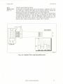
only as reject for cracks. (Fig. 2.2)
In the HOl\.1E page the number of rejects for each class is displayed. If <ENTER> is pressed
when the cursor is positioned on a class, a window pops up which displays the number of
rejects for each defect belonging to that class; this display also includes the indication of
which stations have detected the defects.
The subdivision into classes of defects can be configured, according to different types and
priority of defects.
(For the Classes of Defects and Reject Priority configuration see Appendix B)
ATM18 - Functional
Specifications
11
C9502FEl.DOC
NC9502F.ling
-- ---
---- -- -- -- -- -- -- -- -- -- --
--
-------
Station 2
- nn
n
_<
n
n
__
nn
n
-
Station 3
nnn
n
_"
_n_
u
n
_<
_h_nn
n
nn
n
U
__
n
nn
n
n
- -
- - u
u
n
- -
u
- - __
- - - __
n
n
n
n
- - n
n
n
- - n
- -
- - - - n
n
- - - - u
n
- - - - - - - - - - n
__
u
u
u
__
U
- - __
n
u
- - - - - - n
- - - - - - __
- - n
n
- - __
n
n
______________
- __
__
n
__
~
nn
n
- - n
n
n
- - n
n
__
n
h_
n
n
- _h
"
n
Priority 1
n
Priority 2
Priority 3
uu_
- - - - - - - - - - - - - - - - - - -
n
- - --
- - --
- - --
--
--
Pri 0 rity 5
Priority 6
Fig. 2.2
A separate window displays the following data:
Rejects for Machine Stop
Total Rejected
Total Accepted
Total Inspected
3- permits to store and recall the inspection parameters for the products;
4- features some display and print functions useful for monitoring the production and for system
operation, such as:
4a) "on line" - that is, in real time - detailed display of the inspection result for each station
("ON LINE" menu): while the machine is operating, the screen displays up to four
values of measures performed on the container by the selected station, together with
the time taken by the inspection program for processing the image(s). Furthermore,
some symbols appear which indicate the presence or absence of the container and
whether the container was or was not rejected by the other stations.
4b) comprehensive "on line" graphical display of the inspection result of all stations
("HISTORY" menu): a map of the positions the container fills while it is transported
ITom input to output is displayed; in correspondence to each inspection station a small
square appears. If it is green it will indicate that the station accepted the container, if it
is red it will indicate that the station rejected the container; in case it appears light blue
it will indicate that the station is disabled and did not perform any inspection.
4c) graphical and
("SPINDLES"
By selecting a
total rejected
malfunction of
numerical display of the amount of rejects for each turret spindle
menu): the reject percentage of each spindle is shown with a histogram.
spindle, it is possible to obtain the total containers which it loaded, the
and their percentage. These data is useful to point out possible
the spindles.
A TM18 - Functional Specifications
12
--_ ..__ .__ .--_., ...
,------~-----------------------------
C9 502FE I.DOC
NC9502F.ling
4d) graphical and numerical display of the distribution of the values measured by each
station on the last 1000 inspections performed ("GAUSS" menu): once a station has
been selected, four quadrants appear. Each quadrant shows the values distribution of
one of the quantities analyzed by the program on a max. of 1000 samples (the samples
are the last inspections performed by the station; the number of samples can be preset
by the user). For each distribution shown, the mean and standard deviation are
displayed. Furthermore, a zoom function is available to expand the graph on the x-axis
to make it more readable.
4e) possibility of displaying a list of the last 256 alarms occurred during a production lot.
Each alarm is displayed complete with date and time. Only the alarms with codes
1-1999 (Operating errors) are listed. These alarms usually involve intervention of a
technician to be recovered (see par. 3.4.2). The user can browse the alarm list using
<Pg Up> and <Pg Dn> Keys. The contents of the screen can be sent to the printer
using <Prt Sc> key. When the counters are reset at the beginning of a new lot, the
alarm list is cleared.
4f) possibility of entering product and batch data (two 80 character lines available), which is
displayed in the "Home" screen «F7> key).
If the machine is switched off this data remain stored in a non-volatile memory.
5 - features some test functions useful for performing trials on each single test station and on the
total efficiency of the machine, such as:
5a) utility for Knapp test execution, with print-out of graphical
("KNAPP" menu)
and numerical report
5b) possibility of acquiring an image rrom any station and immediately execute, with the
machine stopped, any processing program for testing purposes ("PROGRAM" menu).
It is possible to change parameters and instructions to check their effect without
original programs and parameters (which are stored in a non-volatile memory) being
changed.
5c) possibility of activating the "Manual" mode ("MANUAL" menu); this is useful, for
instance, for format changeover: it permits to disable lamps and motors without the
machine diagnosing operating errors.
5d) possibility of acquiring an image rrom any station and immediately execute different
processing for testing purposes ("TEST SpIt menu): the gray scale image and the
binarized one are shown in separate windows. The user can change the binarization
threshold and see the effects on the binarized image. Furthermore it is possible to copy
the image in a new window and process it using algorithms as subtraction between two
images or convolution.
5e) possibility of activating an "oscilloscope" function ("OSCIL" menu): a window,
complete with a reference grid, shows a real time oscilloscope-like display of the light
intensity along a row or a column of the image. The user can examine the desired row
or column simply by using the four arrow keys. A red line indicates the level of
binarization; by changing this level with the <+> <-> keys, the red row moves and gives
a help to look for the more appropriate binarization threshold.
5f)
possibility of testing the inputs and outputs with the machine stopped ("TEST HW"
menu).
ATMI8 - Fllllctional Specifications
... /
..'
13
C9502FEl.DOC
NC9502F.l
ing
6 - includes a complete programming environment, reserved to technical personnel; this permits to
write the image processing programs and change the existent ones.
These operations are performed by using an integrated editor; the programs can be saved on nonvolatile memory and on removable memory card.
2.2.2.2 Application software
The application software consists of the image processing programs or SP programs.
The programs are written using a language developed by Brevetti C.E.A., which has specific
functions for image processing.
Each program is assigned to one or more SP systems and executes on the acquired images the
sequence of operations and measures required by the inspection to be performed.
SP Program listings are included in the document [7].
A 1M18 - Functional Specifications
14
C9502FE1.DOC
NC9502F.ling
2.3 MACHINE DESCRIPTION
The machine consists of the following main parts:
1)
2)
3)
4)
Control console
Machine body
Loading line
Unloading line
The containers are moved from the upstream machine by means of a "first-in first-out" line and they
are loaded into the turret by means of a worm screw and a loading star wheel.
Inside the turret the containers rotate on their own axis when this is required by the kind of test to be
performed.
The motion of the turrets is intermittent and the containers' test occurs during the pause from one
traverse and the following one.
At turret output the containers are addressed towards the good or rejected channels by means of two
proper independent devices. There is a box for the reject collection.
The transportation method guarantees a uniform movement of the containers without sudden shifts.
This mechanism is built with materials which cannot damage or dirty the containers.
Materials in contact with the containers:
- 304 Stainless Steel
- 304 Stainless Steel chromium-plated
- Delrin
A TM18 - Functional Specifications
15
C9502FE1.DOC
NC9502F.ling
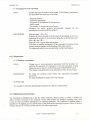
2.4 TECHNICAL NOTES
2.4.1 Performances
Tested containers:
Ampoules
Dimensions of tested containers:
0.5ml
1O.5mmtot.h. 50mm ampoules
10.5mm tot.h. 50mm ampoules
Iml
16.5mm tot.h. 67mm ampoules
6ml
Machine speed:
continuous regulation trom 33 up to 150 pcs/min
Rotation speed:
continuous regulation trom 300 up to 3000 rpm
Inspection stations:
4 stations for each module: 3 for particles test and 1
for levellblack particle test
with "first-in first-out" line with TCM
Loading:
Unloading:
0
0
0
accepted: in "first-in first-out" line with LTM
Jupiter
rejected: standard CEA steel boxes, 130x500x50mm
(WxDxH)
2.4.2 Services required
Electric supply
208V ±5% 60Hz IPh
Power
6KW
ATM18 - FlUlctional Specifications
16
C9502FEl.DOC
NC9502F.ling
2.4.3 Limits
Module-console connection
cables:
15m lenght
Dimensions:
(WxDxH)
mechanic module: 1910 x 860 x 1340mm
console: 1200 x 600 x 21 OOmm
Weight:
mechanic module:
console: 350Kg
Loading/ unloading height:
900mm ±50mm
Minimum height above floor:
mechanic module: 150mm
console: 50mm
Noise:
acoustic pressure level
(continuous equivalent A-weighted)
70dB(A)
Protection level:
mechanic module: within the CEl standard IP22
console: within the CEl standard IP54
900Kg
2.4.4 Working environment
Operating temperature:
Relative humidity:
max. 90%, no condensation
Electromagnetic compatibility:
emission within the CEl EN50081-1 standard limits
Pressure:
0.5 -;-2 bar
2.4.5 Expandability,
interface, options
Software reserve space:
20%
Cabling reserve space:
10% spare terminals
Interface:
RS232C baud (printer)
Options:
in-line connection (with external stop)
Prearrangements:
not applicable
ATM18 - Fill1ctiona1 Specifications
17
C9502FEl.DOC
NC9502F.ling
3. FUNCTIONS
3.1 ACQUISITION SYSTEM
The system of image acquisition and processing is explained into detail in the User Manual. This
chapter sums up its operating in order to give an overall view of the techniques used and facilitate
the understanding of the tests performed by the machine.
The telecamera has a CCD type matrix sensor (Charge-Coupled Device). The sensor consists of
thousands of single elements: each of them supplies a quantity of electric energy proportional to the
quantity of luminous power it receives. The circuits of the telecamera measure all voltage values
supplied by the single elements of the sensor and build a standard CCIR video signal. This signal is
sent by means of a cable to the SP acquisition and processing board. This board samples the signal at
a sampling rate of 8:MHz, that is, it measures the signal level each 125ns; then it converts the
detected value into a number from 0 to 255 (i.e. 0 = black, 127 = gray 50%, 255 = white). A table is
created in memory, and it is filled with the numbers coming from the conversion stage. Each one of
these numbers represents the quantity of light present in a definite point of the image at the moment
of sampling.
This method is called analog to digital conversion or digitizing.
At this moment there is a 144 x 416 table, whose cells contain all information necessary to
understand if the object acquired as an image presents some defects. This map, therefore can be
called "image", or, more precisely, "digitized" image.
The present system permits to acquire up to 8 images while the container stands in front of the
telecamera. The container can be monitored 8 times while it is rotating around its own axis, covering
thus the whole lateral surface. In case of flip-off or bottom test, a unique image is sufficient.
3.1.2
PROCESSING SYSTEM
In all the application programs, both using the "difference method" or the "binarized" one, a test
is pesrformed in order to check if the quantity of light is enough for the correct execution of the
program itself. In the negative the container is rejected termining the program execution.
Moreover, if four consecutive rejects occur for lack of light the machine stops and displays the
message "Station breakdown".
The first processing the image undergoes is the "binarization": the user defines a threshold between
o and 255, so that the system assignes the value "0" to all the elements of the digitized image which
have a value below this threshold, and assignes the value "1" to the ones which have a value above
the threshold ..
Just to make an example, if the object monitored has a middle-grey colour, the image will be a table
full of "127" values, corresponding thus to the middle of the range 0-255. If the binarization
threshold is set at 128, the resulting binarized image will be a table full of "0" values; if the threshold
is set at 126 the table will be full of" 1" values.
In this way we obtain one or more binarized images, consisting only of "0" and" 1" values. If we test
a vial and succeed in lighting it up so that the defects to be detected look darker than the vial glass,
we will set the binarization threshold at such a value that in the resulting binarized image the defect
becomes a completely black spot on a completely white background (that is a group of "0"
values surrounded by "1" values).
The system can be programmed to look for defects in definite zones of the image, to detect bigger
defects than the ones whose dimensions was preset by the user, to make measurements, to detect
presence or absence of particulars.
A TM18 - Functional Specifications
18
C9502FE1.DOC
NC9502F.ling
A second technique is the one based on the "differences", that is used for the search of particles
inside the fluid.
The container rotates and then abruptly stops so that the particles move inside the fluid while the
container stays in :ITontof the telecamera. The SP system is designed to detect only the particles set
in movement, so it acquires the first image (that is the one with a value between 0 and 255 for each
pixel), then acquires the following ones, comparing at every new acquisition the value of each pixel
with the one it had in the first image.
In memory a new table, called "map of differences" is built; in this table is inserted a value "1"
when in any image a pixel presents a variation respect to the first image equal or above the threshold
(difference threshold) preset by the user.
In this way only the particles set in movement are marked: parts of the image such as the silkscreen on an ampoule, even though they are very bright or reflecting, they do not produce luminosity
variations in time and so they are not detected.
The difference method is used also for the alu-cap inspection and the one concerning the lateral
surface of the container. This permits to detect, while the container is rotating, little differences of
light due to the presence of cracks or dents.
The Signal Processor can be programmed to process the map of differences in order to look for
defects in certain zones of the image or in order to eliminate little disturbances present in the image.
A TM18 - Fllilctiona1 Specifications
19
C9502FE1.DOC
NC9502F.ling
3.2 TESTS
What follows is a description of all test stations installed in the machine.
-
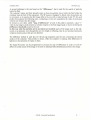
3.2.1
Station TV1
Station TV3
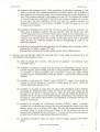
(Fig. 3.1)
PARTICLE TEST
A telecamera, horizontally placed in rront of the ampoules, frames the
ampoule's content, which was previously rotated and abruptly braked in order
that the possible particles present in the liquid are in movement in rront of the
telecamera. The container is lighted up rrom underneath by an halogen lamp
with collimator. The inspection method used is the one "for differences". In
area 1, indicated in the figure, the test is performed. The mask placed between
the ampoule and the telecamera is necessary to cover possible reflections
coming rrom the meniscus, which could cause the reject of the good
containers.
The minimum detectable defect is a particle which has a visible area equivalent
to a square with a 54/lm side.
Mask
TELECAMERA
- -- -- -- -- -- ---- -- -- -- ---- -- -- -- ------ -- -- -- -- -- ---
t... ,
o 0
mask position
for different
filling level
COLLIMATOR
t=Z0
,,
,
HALOGEN
BULB
c9502f31.cdr
Fig. 3.1 - Stations TV1-3: Particle test
........
-.
A TM18 - Functional Specifications
20
C9502FEl.DOC
NC9502F.ling
-
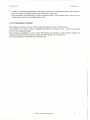
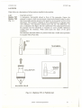
3.2.2
Station TV2
(Fig. 3.2)
PARTICLE TEST ON THE BOTTOM
A telecamera, horizontally placed in front of the ampoules, frames by means of
a 450 inclined mirror the ampoule's bottom.
The test is performed in "instantaneous" way, acquiring only an image while
the container is at a stop. The container is lighted up from underneath by an
annular optical fiber and an halogen lamp; in this way the possible defects will
result black on light background. In figure 3.2 area 1 represents the framed
field, while area 2 represents the test zone.
The minimum detectable defect is a particle with a visible area equivalent to a
square with 220Jlm side, in case the contrast between object and background
is equal to 100%.
r-----------
'''
--,
-
,
!
1
:
'
:
,
I
i
i
L
[
,
Good
ampolule
ANNULAR
LIGHTING
I
I
I
II
I
I
I
I
L
1
.,
J
Ampoule
with particle
FIBER OPTICS
DEVICE
I
II
II
I
I
I
I
TELECAMERA
~---
I
I
I
I
I
I
----------------------------
~------------------------------
MIRROR
c9502f32.cdr
Fig. 3.2 - Station TV2 - Particle test on the bottom
A1M18 - Fllilctional Specifications
21
C9502FEl.DOC
NC9502F.ling
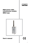
- LEVEL AND PARTICLE TEST
Station TV4
A telecamera, horizontally placed, frames the ampoule. A lighting unit with a
neon lamp and a diffuser filter lights up the ampoule sideways, making the
(Fig. 3.3)
ampoule outlines and meniscus appear black on white background.
The program executes two different tests: first of all it finds in instantaneous
way the meniscus position (1), then uses line 1 as reference line below which
to perform the particle test with the "difference" method (zone A). The
precision for the level check is about 0.5mm while for the particle test it is a
particle with a visible area equivalent to a square with 70 ~m side.
3.2.3
NEON
LAMP
TELECAMERA
------------ -------------
---------------fU4
---- --- - --- -- -- -- --- - -- - -- -- -- -- -- --- -- ---- ---- --
O}.....
DIFFUSED
LIGHT
IllUMINATOR
A
·n·HI'
"rm~j:: : :~- -i --1~----_:'
I
I
~
J
good
ampoule
:
I
I
------,
low
fill level
--filgn-
ampouTe
fill level 'Nith particle
c9502f33.cdr
Fig. 3.3 - Station TV4: Level and particle test
ATM18 - Functional Specifications
22
C9502FE1.DOC
NC9502F.ling
3.3 MECHANICS
3.3.1 Loading
The containers coming ITom the upstream machine by means of an in-line connection are moved to
the loading star wheel by means of a worm screw.
The star wheel, which rotates with continuous motion, moves the containers to the turret in the
moment the spindle - which is still - is in the condition of receiving the ampoule (when the moving
wing is open).
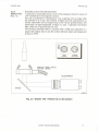
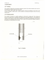
3.3.2 Gripping system
The container is inserted in a spindle consisting of a fixed and a moving part. The moving part
permits the loading and the unloading of the ampoule ITom the spindle (Fig.3.4). The opening and
closing occurs by means of a earn which is fastened to the machine in correspondance with the input
and output of the ampoules ITom the turret. The two parts are removable and change according to
the dimensions ofthe ampoules to be tested.
C4141'33.COR
moving wing
fixed wing
Fig. 3.4 - Spindle
A 1M18 - Functional Specifications
23
_________________________________
•
u
._.
C9502FEI.DOC
.
NC9502F.ling
3.3.3 Output
At the turret output if the container must be rejected a proper actuator hooks a pull-out device in
order to send the ampoule into the rejects box; in case of a good container it proceeds just for a step
and the pull-out device for goods sends it into the in-line connection channel with the LTM, which is
placed downstream.
3.3.4 Protections
a) All parts in contact with the product are made of stainless steel or of plastic material which does
not produce dust and can be removed to permit cleaning.
b) The transportation zone of the containers is separated from the mechanical and electrical parts, so
that the product residues can not reach them.
c) The parts in movement are protected by covers made in plastic material.
d) Access panels to parts that require maintenance can be opened only using a proper tool.
3.4 SAFETY - ERROR AND ALARM MESSAGES
3.4.1 Safety
a) The cover of the loading star wheel is equipped with a device which, in case of opening, stops the
machine in emergency.
b) Mushroom-shaped emergency push-buttons are located around the machine in easily accessible
positions.
The machine stops in emergency for the following reasons:
1) a mushroom-shaped push-button was pressed
2) one of the covers was opened
3) a spindle is not oriented (one of the devices to
orient the spindles could be malfunctioning)
When an emergency stop occurs all parts of the machine stop.
After an emergency stop, the operator must press the emergency-reset
machine again.
push-button to start the
c) Access panels to parts that require maintenance can be opened only using a proper tool.
d) Parts directly in contact with mains voltage are shielded by insulating panels in order to avoid
accidental contacts. The equipment features protections against overloads and earth leakage.
ATMl8
/ ...
':-
;.;.
I
- Functional Specifications
24
C9 502FE l.DOC
NC9502F.l ing
3.4.2 Error and alarm messages
a) Start-up diagnostic test
At power-up, the machine control system performs a series of self-diagnostic tests in order to
check the operating condition of the boards and of the printer. The test results are shown on the
screen until the user does not make any selection from the keyboard.
The tests performed are in this order:
Memory test
Parameter test
Back-up battery test
Board test
Printer test
The following information is displayed for each test:
I Test
description
I Result
I Note
where "result" corresponds to:
"OK" if the test passed
"FAIL" if the test failed
According to the kind of test there can be an additional note: in particular, for the electronic boards
equipped with software the note reports the software release, if the test of the program checksum is
negative the note reports "FAIL" or "ReI. 000".
The typical self-test screen is shown in figure 3.5.
~II~
L......
MOTORS
#6
ReI.
OK.
SIGN.
#0
#7
OK.
PRo
DIGITAL
OK.
#1
Rei.
I/O ....
Parametrt
Flash
......................
Video
Machine
Tenninal
Processor
......
.9.........
...
Memory
Card
Test
Test
Test
Card
2.010
OK. Battery
ReI.
»TEST«
OK.
OK.
~
~
ReI.
Test
~
~ 15r7/95
11:30:15 ~
OK.
<Flash
cleared>
2.010
2.010
1.05
to
key
Test continue
Printer.............................
: OK.
any ...
~~
Press
ID
~
Fig. 3.5 - Typical Self-Test Screen
A 1M18 - Functional Specifications
25
rd
P # (y)
C9502FEl.DOC
NC9502F.ling
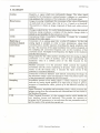
b) Operating errors
The error messages are displayed in order to signal the wrong operation of fundamental parts of the
machine, that would not allow to correctly test the product.
The error messages listed here below, preceded on the screen by the letter "E", are always associated
with an automatic and immediate stop and a 3-second sound signal. Consider them as serious alarms
which require the intervention of technical personnel.
....
-
MESSAGE
CAUSE
MACHINE Power
section
Connections,
SP
board
Motor
speed
too
high;
Encoder;
DM526
board
DM526
board;
DM532
board;
actuator,
Motor,
inverter,
belts,
encoder,
DM522
A
star
wheel
is
optical
out-of-phase
fibers,
amplifier
Stop
..
CONDITION
Lack of Services
Telecamera
+ 12VDC
supply
+24VDC
supply
ATM18 - Functional Specifications
26
C9502FE1.DOC
NC9502F.ling
c) Operational warnings
SIGNAL
The operational warnings, preceded on the screen by the letter "W", do not stand for a bad operating
of the machine, but they advise the operator when some events occur which can alter the machine
operating, or when the operator himself gives an invalid command.
The simple operator's intervention is enough to restore normal condition ..
--------Stop
SOUND
----CONDITION
MACHINE
.DM526
ContiCAUSE
Printer
connections
3 nuous
seconds
manual
Start with
DM522
board
Parameter
Operator's
writing
error
key
noton
Stop
Emergency
push-button;
ampoules;
MESSAGE
Excessive
number
of
ampoules
module (x)
x)
ATM18 - Functional Specifications
27
C9502FEl.DOC
NC9502F.ling
4. INTERFACE
"'--../
All the operations described are performed using the machine's two keyboards:
- Control keyboard, located on the external wall of the loading table
- Console keyboard.
All information is furnished by the computer screen, by the telecamera monitor and by an optional
printer.
4.1 ACCESS LEVELS
Operational Functions are accessed via passwords. The system has two access levels:
1. Operator
2. Supervisor
Two passwords are available for each level. A two character field, which is-constantly displayed in
the video screen heading, shows the current level code. The level codes which can be displayed are
listed below:
- Empty Field:
no level is active, therefore no operational function
can be accessed.
- 01:
Operator level is active under password NO.1
Operator level is active under password NO.2
Supervisor level is active under password NO.1
SUDervisor level is active under Dassword NO.2
- 02:
- S1:
- S2:
When Operator Level is active, access is restricted to the following operational functions:
1. Start and Stop
2. Counter Reset
3. Active Product Selection
When Supervisor Level is active, access to operational functions is extended and includes:
1. Access to Operator Level Functions
2. Inspection Parameter and Program Modification
3. Password Modification
When the machine is switched on, no level is active, therefore no operational function is enabled. By
pressing keys <F7> <F6> <F2> <F1>,the Login command is selected, and the system requests the
user to enter a password. After a password is entered, the user accesses the functions reserved to
that password, and the video screen heading displays the corresponding level code.
The user can select the Logout command (keys <F7> <F6> <F2> <F2» to temporarily disable all
functions. To access them again, a password must be re-entered.
ATM18 - Filllctional Specifications
28
C9502FEl.DOC
NC9502F.ling
4.1.1 Operator
4.1.1.1 Machine operations:
A - Starting and stopping
Machine START (green) and STOP (red) commands are given by illuminated push-buttons present
on the control keyboard. Command activation and acceptance are signalled when the push-button
lights up.
These commands only permit start-up and stop with the machine in phase. Each of the two modules
has got its own control push-buttons.
B - Emergency stop
Immediate machine stop is obtained by pressing one of the self-retaining EMERGENCY pushbuttons (red mushroom-shaped push-buttons), located around the machine in easily accessible
positions. Pressing one mushroom-shaped push-button makes both the modules stop in emergency
mode.
When the EMERGENCY RESET push-button is illuminated, it signals the condition of emergency
stop. Each of the two modules has got its own emergency reset push-button.
At power-up, the machine is set in emergency for safety reasons.
C - Reset after an emergency stop
To restore normal operation you must release the emergency push-button which caused the machine
stoppage and press the interested EMERGENCY-RESET push-button ..
This sequence of operations (Release emergency button-press Reset-press Start) guarantees and
protects the machine operator against the possibility of accidental machine start-up after an
emergency stop.
ATM18 - Functional Specifications
29
.
C9502FEl.DOC
NC9502F.ling
4.1.1.2 Operations on the console keyboard:
The operations here described can be carried out in an independent way on the two modules. In
order to select the operating module, press <FII> key.
A - Display of motor speed
GOAL:
Display the speed of the machine motors for the active product.
This speed is expressed in pieces/ hour for the main motor, in
RPM for the rotation motors and in cm! second for the belt motor.
PROCEDURE:
Selection path: <F7> <FI> <F3>
B - Display of production data (Counters)
GOAL:
Display of the following data:
-
PROCEDURE:
number of tested containers
number of rejects
-'
number of rejects divided by test station
percentages
Selection path <F7>
Press the "Print Screen" key to get a print-out of the video page.
C - Start of production batch
GOAL:
Set the machine up to test a new production batch. This corresponds
to zero the counters and, if necessary, put in the name or the code of
a new batch.
PROCEDURE:
To zero the counters press the following keys:<F7> <F2> <FI> <FI>
and, when required, confirm with <Y>.
Two lines, with 80 alpha-numeric characters each one, are available
to enter batch name, batch number or comments, by pressing the keys
<F7><F2><FI> and <F5> (INFO)
The "Esc" key deletes a complete line.
D - End of production batch
GOAL:
Record the data relative to the inspected batch. It corresponds to
print the data referring to the counters and the parameters, with
which the inspection was carried out.
PROCEDURE:
To print the counters the selection path is:
<F7><Prt Scr>
To print the parameters the selection path is:
test parameters - <F7> <F3> <F5> <Prt Scr>
motor speed - <F7> <F3> <F5> <Prt Scr>
ATM18 - Fllilctional Specifications
30
NC9502F.l:ing
C9502FE1.DOC
E - Changing the active product
GOAL:
Change the type of product being tested. The following parameters
are associated with each type of product:
- Name of product
- Sensitivity parameters
- Programs of the different SP sub-systems
- Motor speed
- Parameters for timing the output boxes
Changing the active product automatically
parameters associated with that product.
PROCEDURE:
changes
all the
Selection path: <F3><Fl>
Position the arrow located in the left part of the display on the row
regarding the product to be activated, using the up and down arrow
keys <~> and <~> .
Press the <F2> key to select the product.
Note that, to confirm acceptance of this command; the name of the
chosen product appears on the heading of the video screen.
To create and record a new product refer to the User Manual..
4.1.2 Supervisor
A - Changing a parameter
GOAL:
Change one or more parameters associated with the product. To
perform this operation it is necessary to own the parameter writing
enable key and to insert it on the front panel of the DM503 board.
The change is possible only on the parameters of the active product.
PROCEDURE:
To make the product active follow the instructions
previously.
To make modifications refer to the User Manual.
described
B - Print-outs
It is enough to select the desired page and press the <Prt SCT>function key.
4.1.3 Maintenance technician
The maintenance technician has a key for safety exclusion, which actuates a switch to disable the
safety switches mounted on the machine covers. This permits the machine operating with open
covers, in order to perform maintenance or repairing operations. The condition of disabled safety is
signalled by the lighting up of a yellow lamp on the panel of the operating keyboard. Each of the two
modules has got its own key-switch and its own yellow signal lamp.
ATM18 - Functional Specifications
31
igital
r
C9502FEl.DOC
NC9502F.1ing
5. GLOSSARY
International
Radio
Consultative
Committee.
It
stands
for
aluminosity
standard
Conversion
ofsignal
an
analog
into
series
of the
numbers.
At
first
analog
Machine
signal
processor:
isaPicture
sampled,
it Element:
the
in
order
processor
toaelement
have
istantaneous
controls
the
values
machine
later
Acquisition
Video
Charge-coupled
converted
Contraction
Terminal
into
process
Processor:
device:
number
of
an
itissequence,
issignal
analog
itnumbers
ain
is
solid
the
each
signal:
state
describing
computer
photosensor
awhich
circuit
section
the
composing
signal
measures
where
which
amplitude
the
the
handles
at
image.
received
regular
step
In
Image
Signal
Processor:
stands
for
the
acquisition
whole
and
processing
resulting
circuit,
from
the
which
analog-to-digital
processes
the
Quantity
or
which
can
continuously
change.
The
video
signal
processing
consisting
the
conversion
of
value
of
Analog
the
telecamera.
Machine
Processor.
only.
of
the
photo
sensors
contained
in
the
CCD
container
is
considered
defected.
format
of
the
video
signal.
and
sampling.
thus
the
accuracy.
,get
the
results
of
the
production
carried
out.
images
coming
from
the
telecameras
and
communicates
result
to
UP
and
amplified
by
the
telecamera
circuits.
picked
of
each
pixel
into
aconversion
binary
value,
that
0sensor.
or
1,
based
onwhite
adepends
threshold.
converter
sequence
sampling
of
circuit.
istantaneous
and
The
values,
is
frequency
the
picked
frequency,
up
and
in
the
on
higher
the-resolution
different
isin
the
moments
resolution
of
of
way
analog
to
the
variations
of
luminosity
of
the
framed
object.
This
permits
to
obtain
an
image
composed
of
black
and
colours
by
the
user
intervals
step.
telecamera
interface
The
accuracy
analog
image
(screen
signal
ahigher
pixel
and
the
applied
keyboard):
corresponds
signal
at
translation
itsis
This
input
to
what
into
permits
and
was
numbers
at
picked
output
the
operator
up
itwhich
gives
by
on
results
of
the
SP
boards
it
actuates
the
reject
device
if one
the
program
the
SP
processors,
to
set
and
store
the
test
parameters
and
supplied
by
the
telecamera
is
analog
because
it
changes
atest
continuous
conversion:
it
is
ain
table
of
numbers,
each
of
them
representing
luminous
energy
produces
atests,
variation
of
the
electric
charge
isa
movements
and
the
correct
operating
of
all
parts.
After
receiving
luminosity
value
aof
definite
point
of
the
field
focused
by
ATM18 - Flillctional Specifications
32
C9502FEl.DOC
NC9502F.ling
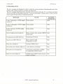
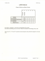
APPENDIX B
Classes of Defects and Reject Priority
o'
>
Q)
LL
4
•....
co
Q)
-L
u
en
.2Fill
A
4a..
3S
7Particles
56
Black
E
Sarticles
P
level
Particles
in the bottom
X1
XC
Defects
Each defect is assigned to a class if the corresponding cell is crossed.
Each defect must belong only to one class. Classes are numbered in descending
priority order.
Note: since TVl, TV2 and TV3 perform the same inspection, they should be assigned to the same
class.
ATM18 - Functional Specifications
Appendix B - Page 1
,,-.
"
(
---_\
1900
820 ~
...../ ..
f~ ')J
.
,-,
I
----" 1730
',,'
"
'\
\
"
'\
\
\
\
I
I
\
1000
I
\ I
"
1/."
\
...•":.."::..-:.
.•.....
\I
,
\
,
t\---.........•.
II
,
"
\\
~
,
':,II
C"")
co
- --
~I
ff'\
~ ),
~ ..j
~
-==-=::1
a
/
I
~
~
'I
I
I \
II
II I
II ,
/",
/
"
I-----:r
\\'
I
\
----~
,
II
\~;';'~
- '- - - ~ \~;',
\,'
•~
/,
"
I ~I
II I I \ \
I'
,"
"
\)
"
I'
"
I
,'1
;,'
,1
2490
:(JI
:C
:'?'
.({'1
II
II'
\
:1
':0
I
II"
/I
i()
I
I
"
///
,
I
;2
,
=====::1
--
"I}
~
I
I
I
II.
II\
"\ I
/
"
I
II
I I
L_J
0'~
::1Lf"t
~
I
I
(/1
{\J
-C\
0
.ii
~
..
\
'~\
_
::1
,\
I~
\
",
"
'~\
.......•
"'.:..-----~/
2320
t
--
.....
\\
,
-j-.IP
\
=====~
I
I
CONSOLE
18!
1200
>1
1<
,j
,~,
~,
\
I
I
I
1210
,I
CUSTOMER
o
o
APPROVED
APPROVED
2
o
~-~
~
um~~
mt
o
o
"i;:
"'j"
FOR INFORMATION
",
II
;,
.
, "':1:,1: ::;:.,
T[M + ATM18 DP + LTM ;'..,::;n:ljt~
lL'
FOR APPROVAL
.' i .:/;j:!:1~ !~!!
1\
AS NOTED
.
DRAWN
APPROVED
VICENZA-IT
AL Y
PF
Dm
7,12.95
D" [ONNAUGHT
":., .•;.' ~~ill;
,',',!
I
:!tNi,~~!~
'" ~,k·
13 ,'i
:;(. REV.