1
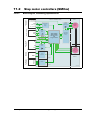
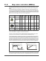
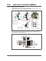
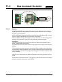
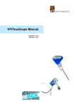
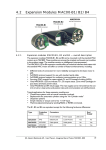
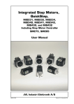
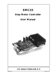
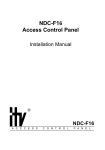
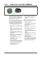
11.2
Step motor controllers (SMCxx)
SMC75
SMC75 mounted in a housing
The compact step motor controller SMC75 is
designed for positioning and speed control of
stepper motors. SMC75 is a PCB with di-
mensions 57x57mm and mounted with
SMD electronics on both sides.
It is mounted directly in the housing of the JVL
QuickStep motors MIS 231, 232 and 234,
forming a complete integrated step motor.
It may also be used with other types of step
motors according to customers requirements.
The basic features of the controller are:
• Serial RS485 or 5V serial position controller
• Position controller with graphic programming.
• Option for CANbus, CANopen DS-301/
DSP-402 or DeviceNet (under development).
• A dual supply facility is available so that
position and parameters are maintained at
emergency stop
• Gear mode
• MACmotor protocol so MACmotor and
Quickstep motors can be connected on
the same RS485 bus
• Command for easy PLC/PC setup and
communication
• Power supply 12-48VDC
• Fixed 1600 pulses/rev.
• Built-in µprocessor with 8 In/Out that can
be configured as inputs, PNP outputs or
analogue inputs. 5V serial and RS485 interface for set up and programming.
• MODBUS interface.
• 9.6 to 1Mb communication
248
• Driver technology is improved as compared to SMD73 and supply voltage is
12-48VDC (Control voltage 1228VDC).
When used with the QuickStep motor or
mounted on any other step motor the advantages of the controller are:
• De-central intelligence.
• Simple installation. No cables between
motor and driver.
• EMC safe. Switching noise remains
within motor.
• Compact. Does not take space in cabinet.
• Low-cost alternative to separate step
or servo motor and driver.
• Stall detect by means of magnetic
encoder with resolution of up to 1024
pulses/rev.
• Interface possibilities to the SMC75
controller:
• From PC/PLC with serial commands via
5V serial or RS485.
• Pulse/direction input. Encoder output.
• CANopen, DeviceNet
• 8 I/O, 5-28VDC that can be configured
as Inputs, Outputs or analogue inputs
• Future option for Profibus DP, Ethernet,
Bluetooth and Zigbee wireless
JVL Industri Elektronik A/S - User Manual - Integrated Stepper Motors MIS23x, 34x, 43x
11.2
Block diagram, Positioning/Speed Control
User I/O connector
Power supply
connector
Main supply
Serial interface
connector
Field Bus
connector
Motor
SMC75 or SMC85 Controller
P+ 12-48V (SMC75)
P+ 12-80V (SMC85)
CVI
1/8 step
Phase A
Driver
1600 step/rev.
Switchmode
Power
Supply
12-28V logic
P- (Ground)
2-phase
stepper
motor
Phase B
Fuse
750mA
CVO
IO1
Output
source
driver
16Bit (SMC75)
32Bit (SMC85)
Microprocessor
with
Integrated Flash
IO8
IN1 Analog 1
Digital 1
Tx
IN8 Analog 8
Digital 8
High speed
digital logic
array
Rx
A-
RS485
driver
B+
1024 ppr
magnetic
incremental
encoder
CAN R
CAN
Tranciever
Optional
CAN L
Encoder
Optional
Multifunction
I/O Interface
11.2.1
Step motor controllers (SMCxx)
A+
AB+
B-
RS422
Optional
JVL Industri Elektronik A/S - User Manual - Integrated Stepper Motors MIS23x, 34x, 43x
TT2140GB
249
11.2
Step motor controllers (SMCxx)
Step Motor Controller SMC75 is a mini-step driver with fixed 1600 pulses/rev., which
has been designed for driving step motors with phase currents of up to 3 Amp/phase
(RMS).
The Controller SMC75 is available in 2 different versions for various applications. It is
built into the QuickStep Integrated Step Motors, but for OEM and low-cost applications
it can be delivered as a PCB or in its own housing with M12 connectors. For easy mounting and service, the version with M12 connectors is recommended. A version with cable
glands can be used for high volume and low cost applications.
Order no.
PCB
SMC75A1
X
SMC75A1AC
X
BOX
CANopen
IO
X
SMC75A1M3
X
SMC75A1W0
1
8
1
8
X
SMC75A1M6
8
4
X
SMC75A1M5
RS485
X
X
8
8
2
1
1
M12
Cable
Glands
X
X
X
1
X
Other combinations and features are also possible for OEM use. See “Connector overview for the MIS23x” on page 32. for further information.
The “box” version which is built into a black aluminium casing provides a very robust
construction that is insensitive to mechanical vibration and electrical noise.
The advantage of using a ministep driver instead of a conventional full-step or half-step
driver is that mechanical resonance problems are significantly minimised. Resonance
most often occurs at slow motor speeds and results either in loss of motor torque or the
appearance of significant harmonics. The principle of the ministep technique is to drive
the motor using a sinusoidal current in the interval between 2 physical full steps. This reduces the step velocity between each step and thus damps any resonance significantly.
Comparison between ministep and full step
Current (%)
150
Ministep
Full step
100
Resonance during full step operation
Position
(Full steps)
6
Overshoot
5
50
4
0
3
-50
2
-100
-150
1
1
2
3
Position
4 (Full steps)
0
TT2158GB
Time
Both 2-phase and 4-phase step motors can be connected to the Controller, which utilises
the “Bipolar Chopper” principle of operation, thus giving optimum motor performance.
250
JVL Industri Elektronik A/S - User Manual - Integrated Stepper Motors MIS23x, 34x, 43x
11.2
11.2.2
Step motor controllers (SMCxx)
SMC75 Connector overview
The connections to the various connectors of the SMC75 PCB board is shown below.
Note that GND and P- are connected together internally.
J4
J3
IO1
User IO
IO2
IO3
IO4
CVO
ARS485
(Communication)
B+
GND
Ground
Rx
RS232 (5V)
Tx
(optional)
1
2
3
4
5
6
7
8
9
10
Recommended connectors
Molex (or equivalent from CViLux)
Crimp contact 50079-8000 x 10
Housing 10 pin 51021-1000 x 1
or
CViLux
Crimp contact CI44T011PEO x 10
Housing 10 pin CI4410 S000 x 1
IO5
IO6
User IO
RS422
(Multifunction I/O)
Ground
RS422
(Multifunction I/O)
IO7
IO8
CVO
B1+
B1GND
A1+
A1-
SMC75 Circuitboard
1
2
3
4
5
6
7
8
9
10
J1 - "Generation 2" connector
J5
J2
1
P+
(Main power)
CAN_H
CAN_L
(Optional)
V+
CAN
1
2
3
4
5
6
2
CVI
(Control voltage input)
3
P(Main ground)
GND
TT2152-02GB
Recommended connectors
Molex (or equivalent from CViLux)
Crimp contact 50079-8000 x 6
Housing 6 pin 51021-0600 x 1
CViLux
Crimp contact CI44T011PEO x 6
Housing 6 pin CI4406 S000 x 1
Recommended connector
Housing:
Crimp terminals:
Molex 08-50-106
Molex 09-91-0300
Pitch = 3.96mm
(Nylon UL94V-0)
The figure below shows the generation 2 connector for future or special purposes.
Please contact JVL for further information.
JVL Industri Elektronik A/S - User Manual - Integrated Stepper Motors MIS23x, 34x, 43x
251
11.3
How to connect the motor
Only SMCxx
BB+
Screen
Step Motor
AGround
A+
Terminate screen only at SMC75
TT2168GB
11.3.1
Cabling
For SMC75 controllers that supply a phase current in the range 0 to 3 A, it is recommended that 0.5mm² cable (minimum) is used to connect the motor to the controller.
(0.75mm² is recommended.)
Motor cable lengths should not exceed 10 metres because of impedance loss. It is possible to use longer cables but motor performance will decrease.
Cables should be securely connected since a poor connection can cause heating and destruction of the connector. Similarly, tinned conductors should be avoided.
Important!
To minimise spurious noise emission from the motor cables and to fulfil CE requirements, shielded cable must be used.
If shielded cable is not used, other electronic equipment in the vicinity may be adversely
affected.
The removable connector must never be removed while a voltage is connected as this
will significantly reduce the lifetime of the connector. Note also that the connector’s lifetime is reduced by repeated connecting/disconnecting since the contact resistance of the
pins is increased.
Note that P- is connected to the chassis and functions as the main ground on the Controller.
See also Motor Connections Section 15.6, page 303, which describes how various models
of motor should be connected to the Controller.
252
JVL Industri Elektronik A/S - User Manual - Integrated Stepper Motors MIS23x, 34x, 43x
11.3
How to connect the motor
Serial connection of phases:
Motor
Torque
A+
SMC75
Parallel
A-
Serial
B+
Velocity
Current for Serial or
Parallel connection
B-
Maximum
current
settting
Example
motor 4.2A
Motor
4-phase
parallel
I x 1.41
4.2 x 1.41 =5.9
Motor
4-phase
serial
I
1.41
4.2
= 3A
1.41
Motor
2-phase
I
4.2A
SMC75
Parallel connection of phases:
I = Nominal current per phase in accordance
with manufacturer's specifications
11.3.2
TT2207GB
Connection of Step Motor
Various types of step motor are available:
1. 2-phase Bipolar (4 connectors)
2. 4-phase Bipolar/Unipolar (8 connectors)
3. 4-phase Unipolar (6 connectors).
Note that Type 3 motors indicated above (Unipolar motors) produce 40% less torque.
This motor type can be used with success but is not recommended if a 4 or 8 wire motor
is available instead. This section will not describe the unipolar type further.
2-phase or 4-phase motors can be connected to the Controllers as follows:
2-phase Motors (4 wires).
This type of motor can be directly connected to the Controller’s motor terminals.
The Controller current adjustment must not exceed the manufacturer’s specified rated
current for the motor.
4-phase Motors (8 wires).
This type of motor can be connected to the Driver in one of the following two ways:
1. Serial connection of phases.
2. Parallel connection of phases.
Selection of serial or parallel connection of the motor phases is typically determined by
the speed requirements of the actual system.
If slow speeds are required (typically less than 1 kHz), the motor phases can be connected in serial. For operation at higher speeds (greater than 1 kHz), the motor phases can
be connected in parallel.
JVL Industri Elektronik A/S - User Manual - Integrated Stepper Motors MIS23x, 34x, 43x
253
11.3
How to connect the motor
11.3.3
Serial Connection
Using serial connection of the phases, a motor provides the same performance (up to
1kHz) as parallel connection, but using only approximately half the current. This can influence the selection of Controller model and enables a Controller rated for a lower motor current to be used. See illustration on previous page.
If the phases of a 4-phase step motor are connected in series, the motor’s rated phase
current should be divided by 1.41. For example, if the rated current is 4.2A, the maximum setting of the Controller phase current must not exceed 3 A when the motor phases are connected in series.
11.3.4
Parallel Connection
With parallel connection of motor phases, a motor will provide better performance at
frequencies greater than 1kHz compared to serially connected phases, but requires approximately twice the current. This can influence the choice of Controller since it is necessary to select a Controller that can supply twice the current used for serial phase
connection. See illustration on previous page.
When the phases of a 4-phase motor are connected in parallel, the specified rated current of the motor must be multiplied by a factor of 1.41. For example, if the rated current
is 2.0A, the maximum setting of the Controller phase current must not exceed 2.83A
when the phases are connected in parallel.
It should be noted that the lower the self-induction of the motor the better, since this
influences the torque at high speeds. The torque is proportional to the current supplied
to the motor.
The applied voltage is regulated by the Controller so that the phase current is adjusted
to the selected value. In practice this means that if a motor with a large self-inductance
(e.g. 100mH) is used, the Controller cannot supply the required phase current at high
speeds (high rotational frequencies) since the output voltage is limited.
254
JVL Industri Elektronik A/S - User Manual - Integrated Stepper Motors MIS23x, 34x, 43x
11.4
11.4.1
How to connect in general
MIS23x: M12 connections
M12 connectors
1
2
2
1
5
5
4
3
3
1
2
8
7
6
5
4
2
3
1
7
3
4
4
6
5
TT2143GB
Example of SMC75 controller connections.
2
5
1
3
4
PWR
I/O5-8
PWR:
RS485
5 pin male
RS485: 5 pin female
I/O1-4: 8 pin female
I/O1-4
RS485
I/O5-8: 8pin female
TT2205GB
5- pole connector
8-pole connector
Pin no.
Colour
Pin no.
Colour
1
Brown
1
White
2
White
2
Brown
3
Blue
3
Green
4
Black
4
Yellow
5
Grey
5
Grey
6
Pink
7
Blue
8
Red
Colour code for standard cables
JVL Industri Elektronik A/S - User Manual - Integrated Stepper Motors MIS23x, 34x, 43x
255
11.5
Quick Start (SMC75A1MxAA)
1 - A+
2 - A3 - B+
4 - B5 - NC
24-48VDC
Step motor
24VDC
brown
white
blue
black
grey
red
white
blue
yellow
11.5.1
1
1
2
3
3
4
5
5
2
4
5
5
2
3
4
1
RS485-USB-ATC-820
Cable RS485-M12-1-5-5
PC with USB input
2
8 (CVO)
3
1 (IO1)
5
1
8
4
7 (IO4)
4 (GND)
7
5
6
TT2169GB
Getting started with the SMC75A1MxAA and MacTalk
1. Connect the cables and Power supply as shown above. Use RS485-M12-1-5-5 cable
if the PC has an RS485 interface, or use the converter RS485-USB-ATC-820 if the
PC has a USB interface. Please note that other models use an 8-pin female connector
and therefore use RS485-M12-1-5-8 cable.
2. Switch on the SMC75.
3. Start MacTalk and wait 5 seconds until it automatically is connected to the motor. If
“no connection” occurs, check the serial cables and the Mactalk set-up. The Baud
rate should be 19200 and the correct com port selected.
4. When a connection has been established, key in values of “running current” and
“standby current” under “Driver Parameters”. Remember to press “Enter” after
each parameter is keyed in. Actual motor values can be seen to the left of the input
field.
5. Set “Startup mode” to select “Position” to enable the motor driver. There should
now be current in the motor phases. Depending on the standby current, the motor
shaft will be fixed. Some current regulation noise should be heard from the motor.
6. The motor and I/O status can be seen to the left under “Status”.
7. At “Motion Parameter”, key in 1600 counts at “Position”. The motor will now turn
one revolution at the speed specified by “Max Velocity”.
256
JVL Industri Elektronik A/S - User Manual - Integrated Stepper Motors MIS23x, 34x, 43x