1
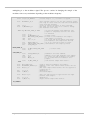
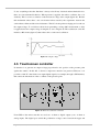
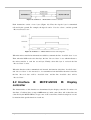
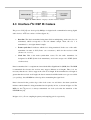
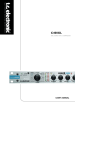
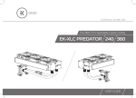
Digital audio console with DSPB56371 and MCF51JM128 By Manuel José Peirone Gustavo Parlanti Rodrigo Germán Molina Digital Signal Processing Laboratory UNC, Córdoba, Argentina 1 Introduction Contents The system introduced in this application note is a digital audio console. It´s based on a DSPB56371 [1], [2] integrated in the 1 Introduction 2 General overview 3 Audio processing stage 3.1 Audio effects Soundbite development kit [3]. This console 3.2 Programmable routing allows to process up to 8 real-time audio 3.3 EQ and filtering signals (grouped in 4 stereo channels: J1, J3, 3.4 Equalizer adjustment J5, J7). It also has 4 stereo output: J2, J4, J6, 3.5 Volume adjustment J8. For control and configuration of the 3.6 Effects control console, the microcontroller MCF51JM128 [4] 4 is employed (integrated in the DEMOJM kit 4.1 Microcontroller MCF51JM128 [5]), which controls a touch-sensitive screen. The DSP communicates to the microcontroller through a data interface specifically designed for this system (see Section 5.1). Configuration and control stage 4.2 Display controller 4.3. LCD screen 4.4 Touchscreen 4.5 Touchscreen controller 5 Interfaces 5.1 Interface A: DSPB56371 MCF51JM128 As said before, the main component of the 5.2 Interface B: MCF51JM128 Display Soundbite kit is the DSPB56371, a 24-bit controller 2 DSP. Its core (derived from 56300 family [6]), 5.3 Interface I S: DSP Codecs is optimized for audio signals processing 6 because it contains differents References modules designed specially for this purpose (DAX, EFCOP, ESAI, etc.). For A/D and D/A convertion, 4 audio codecs are employed: Digital audio console with DSPB56371 and MCF51JM128 1 three AK4556 [7] and one AK4584 [8]. The Soundbite kit allows to program and debug the code using a computer connected through the USB JTAG unit. This means that the code (assembler in this case) can be debugged in real time through the Symphony Studio 1.0.0 [9] IDE provided by Eclipse Project. The MCF51JM128 microcontroller belongs to the Flexis Family. It has a 32-bit ColdFire core, with a 128KB Flash memory and a 16KB RAM memory [4]. As the Soundbite kit, the DEMOJM kit allows real-time debugging of the code through an USB interface. This microcontroller was programmed using C languaje employing the Freescale Codewarrior 5.0.9 platform. In this AN, the attention is focused on the hardware. If someone has special interest in software implementation of the digital signal processing algorithms can look up in [10], [11], [12], [13], [14]. Digital audio console with DSPB56371 and MCF51JM128 2 2 General overview The purpose of this system is to process several real-time audio signals by applying effects, changing the equalization of each stereo channel, etc. This console has 8 input signals grouped in 4 stereo channels J1, J3, J5, J7 and 8 output audio signals, also grouped in 4 stereo channels, so each input channel can be routed to an specific output channel (see Section 3.2). The system is devided in 4 fundamental stages (figure 1): 1. Control stage 2. Source power and touchscreen controller 3. Audio processing stage 4. Touch-sensitive LCD screen Figure 1. System overview Figure 2 shows a block diagram with the system structure, where the most important stages are: audio processing stage and control stage. The first one is based on the DSPB56371 and the audio codecs, while the second one contains the microcontroller, the display controller, the touch-sensitive LCD screen and touchscreen controller. All of these will be described along this AN. Digital audio console with DSPB56371 and MCF51JM128 3 Figure 2. System structure To link each stage, two different data intefaces are used. To communicate the DSP to the microcontroller, interfase A is employed (designed for this application note, see Section 5.1). Then, to transfer data between the microcontroller and the display controller, the interface B is used (see Section 5.2). It consists of 17 address bits (to map a 80KB memory), 6 control bits and 8 data bits. The graphical user interface (GUI) shown in the LCD screen appears in figure 3. To simplify the operation of the system, this interface is devided in 4 general blocks: channel routing, audio processing, EQ and volume control. Figure 3. GUI appearance Digital audio console with DSPB56371 and MCF51JM128 4 3 Audio processing stage As said before, the system core is the DSPB56371, which will process the input audio samples coming from the A/D converters. After this, these processed samples are returned to the D/A converters. The sequence of execution of the differents algorithms is shown in figure 4. The DSP was programmed in assembler languaje. Although the Symphony studio IDE also provides a C compiler, assembler languaje was prefered because of its efficiency (regardless the time it takes to be written). This means that the execution speed of assembler rutines is higher than for the equivalent C code. The A/D converters are delta-sigma. They generate 24-bit samples at 48KHz (though it is possible to work at up to 96KHz with the AK4584 and up to 196KHz with the AK4556). The D/A converters obviously work at the same sampling frequency and word width of A/D converters. The data transfer between the DSP and the codecs is done employing I2S protocol (developed by Phillips for audio devices, see Section 5.3). Figure 4. Scheme of the execution steps in the DSP 3.1 Audio effects The DSPB56371 allows to create almost any kind of audio effect. In the next sections the different implemented effects are explained. Digital audio console with DSPB56371 and MCF51JM128 5 Overdrive distortion. This is a very simple audio effect: its function is to cut the input audio signal. The consecuence is to add harmonics that didn´t exist in the original signal. This is perceived as a higher or lower distortion, depending on the cutting level (parameter a, figure 5). Figure 5. Overdrive distortion The mathematical definition of this effect is: x (t ) if x(t) ≤ a y (t ) = a if x(t) > a Eq. 3.1 Software implementation of the overdrive distortion. The software rutine that generates this effects receives as a parameter the value a (called distortion threshold). Because the cut is simmetrical, the negative threshold is equal (in module) to the positive threshold. move brclr X:CHANNELS_DIST,X0 #0,X0,NO_DIST_J1_LEFT move X:SAMPLE_LEFT_J1,A move Y:THRES_DIST_J1,X0 cmp ble X0,A NO_DIST_UPPER_LEFT_J1 move move Y:THRES_DIST_J1,A A,X:SAMPLE_LEFT_J1 NO_DIST_UPPER_LEFT_J1 move #$800000,Y0 mpy X0,Y0,A move move cmp A,X0 X:SAMPLE_LEFT_J1,A X0,A bge NO_DIST_J1_SAMPLE move X0,X:SAMPLE_LEFT_J1 ; If this flag is ‘0’, no distortion is ; appied. ; ; ; ; ; ; ; ; Distortion on left channel J1 (upper cycle). Distortion threshold (configured outside this rutine). Upper cycle cut. If the input signal is under the threshold no distortion is applied. Distortion threshold. ; ; ; ; ; ; ; ; ; ; ; Lower cycle cut. Y0 is loaded with (-1). The signe of X0 (distortion threshold) is changed. A is temporally saved in X0. Current audio sample. Is the audio sample lower than the distortion threshold? If the audio sample is greater than the lower threshold, no distortion is applied. The result is stored in memory. NO_DIST_J1_LEFT Digital audio console with DSPB56371 and MCF51JM128 6 Figure 6. Flow diagram of the distortion algorithm Fuzz distortion. This is one of the most common effects among guitar players. Its subtleness and body make it a very popular effect, independently of the musical style, although it´s impossible to describe its sound without listening to it personally. This effect, as overdrive distortion, is based on adding harmonics to the original signal. The difference with overdrive distortion is the agresiveness of the harmonics (they are softer in fuzz distortion). For the digital implementation, a multiplication of the signal by it self is done, as many times as the level of distortion required. For example, given the next sine tone: x(t ) = cos(ωt ) Eq. 3.2 Now, if this tone is multiplied by it self, the result is: y1 (t ) = (cos(ωt ) )2 = 1 + cos(2ωt ) 2 Eq. 3.3 This is the second harmonic plus a CC component. If another multiplication is carried on: y 2 (t ) = (cos(ωt ))3 = 3. cos(ωt ) cos(3ωt ) + 4 4 Eq. 3.4 where the fundamental plus the 3rd harmonic is obtained. In this case, there is no CC component, and neither will be for an odd number of multiplications. In figure 7, the results of Digital audio console with DSPB56371 and MCF51JM128 7 equations 3.2, 3.3 and 3.4 is represented in time and frequency domain. The signal y 3 (t ) is the result of 15 multiplications. Figure 7. Fuzz effect results Software implementation of the fuzz distortion. The processing logic for this effect is based on a repeated multiplication of the input signal by it self, as explained before. This is achieved using a hardware loop, as seen in the next source code. Figure 8. Flow diagram of the fuzz distortion algorithm Digital audio console with DSPB56371 and MCF51JM128 8 brclr #0,X0,NO_FUZZ_J1_LEFT ; If this flag is ‘0’, no fuzz is appied. move X: CHANNEL_FUZZ_J1_LEFT,X0 ; The register X:CHANNEL_FUZZ_LEFT contains the ; audio sample to process. This regiter was ; loaded outside this rutine. move move move X: CHANNEL_FUZZ_J1_LEFT,Y0 X0,Y0 X:REPEAT,N do mpy N,Loop X0,Y0,A move A,X0 move X0,X:CHANNEL_FUZZ ; N times hardware loop. N depends on the ; amount of distortion desired. It was ; previously configured by the user. ; N-times multiplication of the signal by it ; self. Loop ; Processed sample storage. NO_FUZZ_J1_LEFT Tremolo. This effect is characterized by small variations in the intensity of an audio signal. It can be implemented by modulating the amplitude with a LFO (low frequency oscillator). Based on the system shown in figure 9, it can be written that: ym (t ) = x(t ).m(t ) Eq. 3.5 m(t ) = co + a. cos(ωot ) Eq. 3.6 where: (a) (b) Figure 9. Tremolo implementation (a); LFO signal (b) The value of co determinates the point where the modulator will be positioned, while the parameter a set the amplitude (or the modulation deepness). The frequency ω0 varies typically between 1 and 10Hz. The parameter a and the frequency are configurable through the touchscreen. Software implementation of the tremolo. To generate the sine modulator signal, a sine tone was sampled and stored in the DSP memory, which allows to modulate the input signal by Digital audio console with DSPB56371 and MCF51JM128 9 multiplying it to the modulator signal. The process consists in changing the sample of the modulator sine every certain time depending on the modulator frequency. brclr #15,X0,NO_TREMOLO ; If this flag is ‘0’, no tremolo is appied. move X:TREMOLO_J1,A add move #1,A A,X:TREMOLO_J1 ; ; ; ; ; ; This register (there´s one for each channel) counts how long it´s been since the last time the modulator sine value was changed. Count up another execution of this algorithm. The next ‘IF’ block asks if it´s time to change the modulator sine value. .if A <EQ> X:LIMIT_TREM_J1 THEN move move move add cmp ; If the time between each modulator sine ; sample is completed, then the ‘IF’ block ; is executed. #0,X0 X0,X:TREMOLO_J1 X:POINTER_SINE_TREM,A #1,A #$000010,A beq move bra ; ; ; ; ; RESET_TREM_J1 ; A,X:POINTER_SINE_TREM ; CONT_TREM_J1 move move X0,X:POINTER_SINE_TREM X0,A move add move move #SINE_TREMOLO,X0 X0,A A,R0 X:(R0),X0 move X0,X:G_TREM_J1 Counter reset. Pointer to the modulator sine sample. Next sample is pointed. Is it the end of the memory range where the modulator sine samples are stored? If it is, then the pointer is reset. New modulator sine sample pointed. RESET_TREM_J1 ; Pointer reset. CONT_TREM_J1 ; ; ; ; ; ; Modulator sine base address. Address of the next modulator sine sample. R0 points the next modulator sine sample. X0 is loaded with the modulator sine sample. Left channel sample with tremolo. .endi move move X:G_TREM_J1,X0 X:CHANNEL_TREMOLO,R0 move X:(R0),Y0 mpy move X0,Y0,A A,X:(R0) move X:(R0+1),Y0 mpy move X0,Y0,A A,X:(R0+1) ; ; ; ; ; ; ; Load X0 with the modulator sine sample. Address of the left channel where tremolo will be applied. The audio sample where tremolo will be applied is loaded into Y0. Modulation. Processed sample. ; ; ; ; Now, the same process is applied over the right channel audio sample. Modulation. Right channel sample with tremolo. NO_TREMOLO Digital audio console with DSPB56371 and MCF51JM128 10 Figure 10. Flow diagram of the tremolo algorithm Delay. This effect is based on generating a delayed copy of original signal and then adding them together (figure 11). Depending on the Tdelay time the ear will percieve different sensations. Figure 11. Delay aplicado a una señal de audio Digital audio console with DSPB56371 and MCF51JM128 11 For a delay longer than 100mS an echo is heared, while for shorter delays the effects are very dependent on the Tdelay chosen. For the digital implementation, the system of the figure 12 is employed. The parameter a es generally lower than 1 and its function is to simulate the acoustics characteristics of the enviroment where the sound is produced (there will be difusion due to the dispersion of sound and energy disipation). Figure 12. Digital delay structure Figure 13. Memory assignement Digital audio console with DSPB56371 and MCF51JM128 12 Software implementation of the delay. The DSPB56371 contains three internal memory blocks: • Program memory (4K x 24) • X data memory (36K x 24) • Y data memory (48K x 24) Each memory has its own data bus (extended harvard architecture). This allows a lot of operations to execute in parallel. The memory map (figure 13) shows how each block of memory has been assigned. In this AN, X data RAM memory is where the audio samples related to the left channel are stored (left samples storage). While, the Y data RAM memory contains the samples related to the right channel. The delay implementation consists in generating a time delay (figure 11). This implies to store in memory the past audio samples and put them back in the output separately according to Tdelay (figure 12). The memory map (figure 13) shows where the audio simples are stored for the delay algorithm. The memory range reserved to store past audio samples is $0C300 - $012000. So, there are almost 24000 available registers for the left channel, and the same amount for right channel. The longest possible delay at 48KHz is half a second, because there´s capacity for a half of the samples taken in one second. Due to the limitation in the amount of internal memory, this effect can be applied to only one channel at a time. The source code that generates the left channel delay is shown next. For the right channel, the logic is the same. DELAY_LEFT brclr #15,X0,NO_DELAY_LEFT ; If this flag is ‘0’, then no delay is appied. move X:CHANNEL_DELAY,R5 move X:ADDRESS_DELAY,R6 ; ; ; ; ; R5 now contains the address of the delaied channel This variable is loaded when the user configures the effect (outside this rutine). R6 now contains the address of the register that contains the past sample stored in memory. move move move maci X:(R6),X0 X:(R5),Y0 Y0,A #$400000,X0,A move move A,X:(R5) Y0,X:(R6) ; ; ; ; ; ; ; ; ; ; X0 is loaded with the stored past sample. Y0 is loaded with the current audio sample. The current sample is loaded into A. The delaied audio sample is modified by a constant a = 0.5, that simulates the characteristics of the room where the delay occurs. Then, it is added to the current sample. Processed sample. The current sample is stored in memory to generate the next delay. Digital audio console with DSPB56371 and MCF51JM128 13 move (R6)+N6 ; The pointer to the stored samples is incremented. .if R6 <EQ> X:TIME_DELAY then move #>$C304,R6 ; ; ; ; ; This ‘IF’ block asks if the end of the past samples memory has been reached. In that case, the pointer is reset. The pointer is reset, loadind the base address of the past samples memory block. .endi move R6,X:ADDRESS_ DELAY ; The past samples memory pointer is saved. NO_DELAY_LEFT Figure 14. Flow diagram of the delay algorithm Digital audio console with DSPB56371 and MCF51JM128 14 Reverberation. Physically, the reverberation is an natural acoustic phenomenon generated in closed enviroments where reflections are possible. These reflections overlap with the main source with differents delays, according to the size of the place and the materials employed to build it. To implement a digital reverberation, it´s necessary to generate differents feedback delays. To do this, there are a lot of structures. Figure 15 shows the structure chosen for this application. The parameter a is always lower than 1. Because this system has a feedback path, an infinite impuse response is produced (this response is heard until the sound goes under the audition threshold). Figure 15. Digital reverb structure Software implementation of reverb. Figure 15 shows that only one delay path is necessary. The main difference with the delay algorithm is the feedback path. The next source code is the digital implementation of the reverberation. REVERB_LEFT brclr #15,X0,NO_REVERB_LEFT ; If this flag is ‘0’, then no delay is appied. move X:CHANNEL_REVERB,R5 ; R5 now contains the address of the channel with ; reverb. This variable is loaded when the user ; configures the effect (outside this rutine). move X:ADDRESS_REVERB,R6 ; R6 is loaded with the address of the register ; that contains the past sample. move X:(R6),X0 ; X0 is loaded with the past sample. move move maci X:(R5),Y0 Y0,A #$400000,X0,A ; Y0 is loaded with the current audio sample. move mpy A,X0 #$600000,X0,A ; The last result is stored in X0. ; Now, it´s affected by a constant a = 0.75 move mpy add move A,X1 #$C00000,Y0,A X1,A A,X:(R5) ; ; ; ; move move A,X:(R6) (R6)+N6 ; The result is stored in memory. ; The pointer to the stored samples memory block ; is incremented. ; The past audio sample is modified by a ; constant a = 0.5. Then, it is added to the ; current sample. .if R6 <EQ> X:TIME_REVERB then Temporal storage. The input sample is multiplied by “-a”. The results obtained so far are added. Processed sample with reverb. ; This ‘IF’ block asks if the end of the Digital audio console with DSPB56371 and MCF51JM128 15 move ; ; ; ; ; #>4,R6 past samples memory block has been reached. In that case, the pointer is reset. The pointer is reset, loading the base address of the past samples memory block. .endi move R6,X:ADDRESS_REVERB ; The past samples memory block pointer is saved. NO_REVERB_LEFT Stereo crossover unit. A crossover unit can not be considered an effect because it doesn´t change the intrinsec characteristics of the original signal. It only separates frequencies, i.e., it splits the spectrum in differents channels. For a two way crossover unit, as implemented in this application note, the goal is to separate the input signal spectrum in two channels, where one of them will contain the low frequency band and the other one the middle a high frequency band. To achieve this, 2nd order filters are used. The crossover frequency is 100Hz. Figure 16. Crossover unit structure Software implementation of the stereo crossover unit. Because the crossover unit consists of two filters (for each mono channel), the explanation is made in section 3.3 (EQ and filtering). 3.2 Programmable routing One advantage of using several output channel is that a different mix of the input channels can be made in each output. To do this, the LCD screen shows a block where the input/output channels are represented. Each column is an output channel, and each row is an input channel. The selected input channel, in each column, will be routed to the corresponding output. Digital audio console with DSPB56371 and MCF51JM128 16 Figure 17. Channel routing configuration 3.3 EQ and filtering Generally speaking, the equalization process (EQ) consists in amplifying or attenuating some specific band of frequencies to improve the quality of a musical piece, avoid acoustic feedback, etc. In this application note, a 5 band equalizer is implemented for each stereo channel. It consists of 5 filters in parallel for each mono channel (figure 18), which results in 10 filters for one stereo channel. The frequency cut-off (table 1) are selected to prevent gaps in the frequency spectrum when flat equalization is set. Figure 18. Architecture of the equalizer (mono channel) The EQ output consists of a weighted sum of the result of each individual filter: Digital audio console with DSPB56371 and MCF51JM128 17 y[n] = y1[n].G1 + y2 [n].G2 + y3[n].G3 + y4 [n].G4 + y5[n].G5 Eq. 3.7 Table 1. Filter frequency cut-off Filter Low frequency cut-off High frequency cut-off 1 100Hz - 2 100Hz 500Hz 3 500Hz 2000Hz 4 2000Hz 8000Hz 5 8000Hz - The filters are second orden sections implemented using direct-form I and they have an infinite impulse response (due to the feedback, figure 19), because this is most suitable configuration for audio applications ([13], [14]). Figure 19. Filter structure The output of each filter is given by the next difference equation: y[n] = x[n].b0 + x[n − 1].b1 + x[n − 2].b2 − a1. y[n − 1] − a2 . y[n − 2] Eq. 3.8 Software implementation of the EQ algorithm. Each equalizer consists of 5 identical filters, so only one algorithm is described. The first step to execute is to adjust the address registers (R[0-7]) to point the input/output samples and the filter coefficients. Next, the “2ND_ORDER_FILTER” subrutine is called, which implements eq. 3.8. Finally, the input/output samples are stored in memory for the next time the algorithm is executed. Digital audio console with DSPB56371 and MCF51JM128 18 FILTER1_LEFT_J1 move #F1_IN_LEFT_J1,R0 move #F1_OUT_LEFT_J1,R1 move #COEF_B1,R4 move #COEF_A1,R5 move X:SAMPLE_LEFT_J1,X0 jsr 2ND_ORDER_FILTER ; ; ; ; ; Past input samples pointer. The address registers R0 and R1 are used because the past samples are stored in X data RAM memory. This way, the benefits of the DSP architecture can be used. Past output samples. ; ; ; ; Numerator coeffients pointer. Registers R4 and R5 are used because the coefficients are stored in Y data RAM memory. Denominator coefficients pointer. ; X0 is loaded with current input sample (X0 is the ; input register to the filtering subrutine). ; Filtering subrutine is called. ; Storage of the audio samples for the next time this rutine executes. move move X:F1_IN_LEFT_J1,X0 X0,X:(F1_IN_LEFT_J1+1) ; The past input samples are rotated in memory. move X:F1_OUT_LEFT_J1,X0 ; The past output samples are rotated in ; memory. move move X0,X:(F1_OUT_LEFT_J1+1) A,X:F1_OUT_LEFT_J1 ; The accumulator contains the result of the ; filtering process. Figure 20. Flow diagram of the filtering algorithm The filtering algorithm is: Digital audio console with DSPB56371 and MCF51JM128 19 ;--------------------------------;---- SECOND ORDER IIR FILTER ---;--------------------------------2ND_ORDER_FILTER ; X0 contains the current input sample. ; The accumulator contains the result of the filtering algorithm. clr move A Y:(R4)+,Y0 ; The first numerator coefficient is loaded into Y0 (b0). ; Convolution of the input samples with the filter coefficients. rep macr macr ; #2 X0,Y0,A X0,Y0,A ; Number of repetitions = Filter order. X:(R0)+,X0 X:(R1)+,X0 Y:(R4)+,Y0 Y:(R5)+,Y0 Convolution of the output samples with the filter coefficients. rep macr #2 X0,Y0,A X:(R1)+,X0 Y:(R5)+,Y0 rts The signed multiply, accumulate and round instructions (MACR) make the heavy duty work. Besides, they take advantage of the parallelism provided by the address generation unit (AGU), because in one clock cycle these instructions can multiply, accumulate, round and update register X0 and Y0 with the data pointed by address registers, which are postincremented. This is possible due to the harvard architecture and the seven-stage pipeline [2]. All of this is executed following these steps: 1. MACR instruction multiplies the data stored in X0 and Y0. The result is accumulated in A. 2. It copies the data pointed by R0/R1 (in X data memory) to X0 and then increment R0/R1. This is called post-increment, because its done after data movement. Finally, it copies the data pointed by R4/R5 (stored in Y data memory) to Y0 register. The rounding mode depends on the state of Scaling Mode bits S0 and S1 in the Status Register. Two types of rounding are implemented: convergent rounding and two’s-complement rounding. In this application note, the first one is employed. For more information, refer to page 3-7 of the DSP56300 Family Manual [6]. 3.4 EQ adjustment To modify the EQ configuration, the LCD screen provides a specific section for this purpose Digital audio console with DSPB56371 and MCF51JM128 20 (figure 3). By touching the horizontal bars and moving them up and down the amplitude of each band of frequency can be changed. Figura 21. EQ appearance 3.5 Volume adjustment Each input/output channel has its own volume fader, which can be modified individually through the touchscreen. When a channel is selected in the channel routing block (figure 22) then, the “Vol. IN” fader modifies the level of this channel, while the “Vol. OUT” fader does the same but for the output channel corresponding to the selected column. Figure 22. Volume adjustment 3.6 Effects control The effects implementation was explained in section 3.1. To configure each one of them, it´s necessary to select them in the audio processing block and then choose the channel that requires the effect (at the bottom of this block). When an specific effect is selected, the configuration options will appear inside this block. For the example of the figure 23, the left picture shows that a reverb has been selected for channel J5. The right picture shows that the overdrive distortion is being applied to channels J3 and J5. Digital audio console with DSPB56371 and MCF51JM128 21 Figure 23. Effect configuration block Digital audio console with DSPB56371 and MCF51JM128 22 4 Control and configuration stage Any system that must interact with an user requires some kind of configuration interfase. In this case, the user interfase is a touch-sensitive LCD screen, which allows the user to see the state of the system and configurate it. The MCF51JM128 controls this touchscreen. Its 128KB of internal memory are perfect for storing the images that will represented on the screen. 4.1 Microcontroller Freescale MCF51JM128 The characteristics that distinguish this microcontroller are (the most important ones for this application highlighted): 32-bit ColdFire V1 core. Its high processing capability is very important for the optimized execution of C rutines. 128 KBytes Flash memory. The size of this memory is very important for storing the images that will be represented on the screen. 51 general purpose input/output ports. This feature allows the microcontroller to interact with many external peripherals (touchscreen, DSP, etc.) 16 KBytes RAM memory USB interfase 12 bit A/D converter Two SPI interfases 4.2 LCD screen controller Unlike other cases, the LCD screen used in this work doesn´t include a controller, which function is to generate all the synchronism signals for image representation. Thankfully, there is a very popular controller, the SED13705, which has the capability to do this work. So, the work of the microcontroller can be focused on other tasks, such as the communication to the DSP. To represent an image, the MCF51JM128 must write the data into the internal memory of the SED13705 , and this one will do the rest of the work. The microcontroller is communicated to the SED13705 through interface B, described in section 5.2. 4.3. LCD screen Digital audio console with DSPB56371 and MCF51JM128 23 It´s a passive liquid crystal display lit by a cold cathode fluorescent lamp (CCFL) which is powered by a 500V source power, obtained from an 5V inverter. Its resolution is 320 x 240 pixels and its size (diagonal) is 5.6”. 4.4. Touchscreen The touchscreen employed is based on a resistive technology. It consists of two films separated by an insulating material, such as glass (figure 24) that touch each other when pressure is applied. There are two different kinds of resistive touchscreen: 4-wire touchscreen and 8-wire touchscreen. For this application, the first one is chosen. X-axis measurement. When the user presses against the surface, the upper semiconductor film (previously polarized with a voltage source) bends just enough to contact the lower semiconductor film. So, they generate a resistive divider (figure 25) because the upper film transfers its voltage to the lower film. This voltage can be measured in any of the wires connected to the bottom film. This voltage is proportional to the location of pressure point in Xaxis direction. Y-axis measurement. The mechanism is the same as for X-axis measurement. The only difference is that the polarization voltage source is applied to the lower film instead of the upper film, and the voltage proportional to Y-axis position is measured in any of the wires connected to the upper film. Figure 24. Touchscreen technology Figure 25. Equivalent resistive divider The microcontroller MCF51JM128 is in charge of measuring these coordinates, through the touchscreen controller (see next section). Digital audio console with DSPB56371 and MCF51JM128 24 So far, everything works fine. But there´s always a but. In any electrical and mechanical device, there are some unwanted behaviors. When pressure is applied, the surface oscillates due to its elasticity. This is seen as a variation of the measured voltage at the output (figure 26). Besides this mechanical effect, there´s also an electrical effect caused by the capacitance between the semiconductor films and the wires inductance. This LC circuit produces ringing and overshot at the output voltage. To avoid these effects from generating a wrong ADC measurement, a delay is applied before the output voltage is sampled, as seen on figure 26. The touchscreen controller includes a RC circuit (figure 27) that reduces this overshot and oscillation. Figure 26. Output voltage 4.5 Touchscreen controller Its function is to generate an output voltage proportional to the position of the pressure point against the surface. In this AN, a discrete component controller was prefered. However, it is possible to find IC´s that deliver an output digital signal (for example, through a SPI interface) that carries the information of the coordinate of the pressure point. Figure 27. Discrete touchscreen controller Four GPIO of the microcontroller are used, two of them as digital outputs y two of them as analog inputs. The digital ports switch the polatization voltage source between the upper and Digital audio console with DSPB56371 and MCF51JM128 25 lower film, using four transistors. On the other side, analog inputs must read the voltage delivered by the resistive divider. Later, the microcontroller software will determinate the XY coordinate of the pressure point. Digital audio console with DSPB56371 and MCF51JM128 26 5 Interfaces Because of this is a digital audio application, it is necessary to employ a DSP for real-time signal processing. At first, it can be thought that this processor will be enough for the entire system. But it´s also necessary to drive the LCD screen, the touchscreen controller, etc. and it´s impossible to do it all with the DSP only. Therefore, the microcontroller MCF51JM128 comes up (see Section 4.1). This implies that the DSP must communicate to the microcontroller and vice versa. The purpose of this section is to explain the data interfaces used in the system to communicate the different blocks. The application can be divided in four general blocks, which must communicate through three data interfaces: • DSPB56371. Its function is to process the input audio signals. It communicates to the audio codecs through the I2S interface (section 5.3). • Codecs. As said in previous sections, their function is to vinculate the discrete-time domain and continious-time domain through the A/D and D/A converters. The samples are exchanged with the DSP by mean of the I2S protocol. • MCF51JM128. It handles the information that appears on the LCD screen and reads the coordinates delivered by the touchscreen. It´s also in charge of “telling” the DSP the configuration decisions that the user has made. • Display controller. It communicates to the microcontroller through interface B (section 5.2). 5.1 Interface A: DSPB56371 MCF51JM128 The comunication between the DSPB56371 and the MCF51JM128 (Figure 28) is done through a data interface that consists of a data bus (8 bidirectional lines), an “Available data” line controlled by the MCF51JM128 (if ‘1’, there´s available data waiting to be transmitted) and a “Received data” line controlled by the DSP (if ‘1’, the data has been succesfully received) The basic idea is to transmit instructions that tell the DSP the operations to execute over the audio signal, based on what the user has chosen in the LCD screen. Digital audio console with DSPB56371 and MCF51JM128 27 Figure 28. DSPB56371 – MCF51JM128 interface structure Each instructions consist of two bytes (Figure 29). First, the Opcode byte is transmitted followed by the operand. For example, the Opcode can be “Vary the volume”, and the operand “How much must it vary”. Figure 29. DSPB56371 – MCF51JM128 interface time diagrams When the microcontroller has information available to transmit, the line “Available data” is set. Then, when the DSP receives the first byte, the line “Received data” is set, which indicates to the microcontroller to send the second byte. Finally, when this byte is recieved the line “Received data” is reset. When the direction of the communication is inverted, the function of the lines “Available data” and “Received data” is also inverted, i.e., for transmitions from the DSP to the microcontroller, the line “Received data” will be “Available data” and the line “Available data” will be “Received data”. 5.2 Interface controller B: MCF51JM128 Display The characteristics of this interface are determinated by the display controller. It consists of 8 data lines, 17 address lines (to map a 80KB memory) and 6 control lines. All of these lines are controlled by the MCF51JM128, except some of the control lines. In this description, it won´t be mentioned the specific function of each one. Digital audio console with DSPB56371 and MCF51JM128 28 Figure 30. MCF51JM128 – Display controller interface structure 5.3 Interface I2S: DSP Codecs The protocol I2S [15] was developed by Phillips for digital audio communication among digital audio devices. A I2S bus consists of 3 lines (figure 31): • Data line. The data is transmitted using time-division multiplexing. At first, the slot 0 is transmitted, which corresponds to the left channel sample. Then, the slot 1 is transmitted, i.e., the right channel sample. • Frame synch line. It indicates which slot is being transfered. In the case of the audio transmitter, its name is FST (Frame sync transmitter), while for the receiver is FSR (Frame sync receiver). • Clock line. This is the main synchronism source. For the audio transmitter, its designated as SCKT (Serial clock transmitter), and for the receptor it´s SCKT (Serial clock receiver). Data is transmitted in 2´s complement form with the Most Significant bit (MSB) first. The MSB is transmitted first because the receiver may support different word lengths. Thus, it is not necessary that the two devices support the same word length. If the transmitted word length is greater than the received word length, the data is truncated and filled with zeroes (process called zero-padding), but still MSB has a fixed position, mantaining the signal level. Data is detected in the positive edge of the clock source. As said before, the frame synch line indicates which channel is being transmitted and is tipically 32 bits, as shown in figure 31. The MSB, for the I2S protocol, is always transmitted one clock cycle after the transition of the FST/FSR line [15]. In figure 31, fs y Tm are sampling frequency and sampling period, respectively. Digital audio console with DSPB56371 and MCF51JM128 29 2 Figure 31. I S protocol structure In an audio system communicated through I2S protocol, only one device is in charge of synch clock generation. This is known as the master device, while the rest is known as the slave devices. In this application, the codec AK4584 is the master device. The DSP and the rest of the codecs work as slave devices. Digital audio console with DSPB56371 and MCF51JM128 30 6 References [1] DSP56371 Data Sheet, Rev. 4.1, 1/2007 [2] DSP56371 User Manual, DSPB56371UM, Rev. 2.1, 08/2006 [3] Symphony SoundBite Demo User's Guide, SNDBDMOUG [4] MCF51JM128 Data Sheet, MCF51JM128, Rev. 2, 09/2008 [5] DEMOJM User manual, DEMOJMUM, Rev. 1.00, 1/2008 [6] DSP56300 Family Manual, DSP56300FM, Rev. 5, 4/2005 [7] Codec AKM AK4556, MS0559-E-00, 11/2006 [8] Codec AKM AK4584, MS0118-E-00, 11/2001 [9] Symphony Studio Eclipse for Symphony DSPs. User guide, SPSTUDIOUG, Rev. 1.1, 07/2008 [10] Implementing a 10-Band Stereo Equalizer on the DSP56311EVM Board, AN2110, Rev. 1, 11/2005 [11] Programming the DSP56300 Enhanced Filter Coprocessor (EFCOP), APR39, Rev. 1, 8/2005 [12] Schaum's Outline of Digital Signal Processing, Monson Hayes. 1999. [13] Ronda Wilson. Filter topologies. AES. [14] Wei Chen. Performanceof Cascadeand Parallel IIR Filtres. AES. [15] Enhanced serial audio interface (ESAI), Programming and Interfacing Techniques. AN1848/D. Rev. 1.0. 05/00. Digital audio console with DSPB56371 and MCF51JM128 31