1
USER'S MANUAL
JSC-3000-10 ANG
ELEVATOR CONTROL PANEL
CC MOTOR VARIABLE SPEED
CJ1M + ETSD PROCESSOR
MAGNETEK SCR VARIABLE SPEED DRIVE
JSC-3000 SERIES
CODE B44-10
VERSION
JSC-3000_A_10-1.2
TABLE OF CONTENT
1.
LCD USE (JRT-LCD): ............................................................................................................................................................ 1-1
1.1.
1.2.
2.
KEYBOARD: ..................................................................................................................................................................... 1-1
MENUS: ............................................................................................................................................................................ 1-2
1.2.1. Monitoring menu: ............................................................................................................................................ 1-2
1.2.2. Register Access menu: ..................................................................................................................................... 1-3
1.2.3. Active faults list menu: ..................................................................................................................................... 1-6
1.2.4. Construction mode menu: ................................................................................................................................ 1-6
1.2.5. Recording floor position menu: ....................................................................................................................... 1-7
1.2.6. Elevator options menu: .................................................................................................................................... 1-7
1.2.7. Password menu: ............................................................................................................................................... 1-8
USE OF THE PROGRAMMING CONSOLE (PRO01 OU PRO27): ................................................................................. 2-1
2.1.
2.2.
2.3.
PROGRAMMING CONSOLE CONNECTION: .......................................................................................................................... 2-1
2.1.1. On the CJ1M PLC NTSD: ................................................................................................................................ 2-1
VISUALISING AND MODIFYING A DM (ELEVATOR CONFIGURATION): ............................................................................... 2-2
CONSULTING THE ALARMS: .............................................................................................................................................. 2-2
3.
TEMPORARY START-UP: ................................................................................................................................................... 3-1
4.
MECHANICAL EQUIPMENT INSTALLATION: ............................................................................................................. 4-1
5.
FINAL START-UP: ................................................................................................................................................................. 5-1
6.
CONTROLLER TYPE: .......................................................................................................................................................... 6-1
6.1.
6.2.
6.3.
6.4.
6.5.
7.
TWO CAR GROOP CONTROLLER (WITHOUT DISPATCHER): ................................................................................................ 6-1
GOUP CONTROLLER (WITH DISPATCHER): ........................................................................................................................ 6-1
CLOCK SETTING ON DISPATCHER WITH OPERATOR SCREEN: ............................................................................................. 6-3
CALL DISPATCH CONFIGURATION, USING THE OPERATOR SCREEN: .................................................................................. 6-4
PEAK HOURS SETTINGS: ................................................................................................................................................... 6-6
INSTALLATION OF MECHANICAL EQUIPMENT: ....................................................................................................... 7-1
7.1.
7.2.
7.3.
PROCEDURE FOR INSTALLATION OF MAGNETIC SWITCHES PROVIDED BY AUTOMATISATION JRT INC.: ............................. 7-1
7.1.1. If Automatisation JRT provides the magnetic switches: .................................................................................. 7-2
DISTANCES INSTALLATION OF MECHANICAL OR MAGNETIC SWITCHES TO EXTREME LEVELS: .......................................... 7-4
7.2.1. Required switches for 250 FPM: ..................................................................................................................... 7-4
7.2.2. Required switches for 300 FPM: ..................................................................................................................... 7-6
7.2.3. Required switches for 350 FPM: ..................................................................................................................... 7-7
7.2.4. Required switches for 400 FPM: ..................................................................................................................... 7-8
7.2.5. Required switches limit for 500 FPM: ........................................................................................................... 7-10
7.2.6. Required switches for 700 FPM: ................................................................................................................... 7-11
7.2.7. Required switches for 750 FPM: ................................................................................................................... 7-13
7.2.8. Required switches for 1000 FPM: ................................................................................................................. 7-14
INSTALLATION OF THE SELECTOR TAPE, NTSD/ETSD ENCODERS ON THE GOVERNOR, MOTOR SHAFT OR THE
SHEAVE: ......................................................................................................................................................................... 7-16
7.3.1. Installation of the perforated tape: ................................................................................................................ 7-16
7.3.2. Installation of the standard tape selector and NTSD / ETSD encoders: ........................................................ 7-17
7.3.2.1. Encoders installation on the governor: ....................................................................................................................... 7-18
7.3.2.2. Encoder installation on the sheave: ............................................................................................................................ 7-18
7.3.3.
7.3.4.
8.
Installation of the "Door Zone" and bar code magnets at each floor: ........................................................... 7-19
Magnets installation with guide locating magnets DZO et P1 à P5 (IP1200-TP1):...................................... 7-21
OPERATION PRINCIPLE FOR ELEVATOR: ................................................................................................................... 8-1
8.1.
ZONING AND LEVELLING: ................................................................................................................................................. 8-1
8.1.1. Posi1000 positioning system encoders calibration:......................................................................................... 8-1
8.1.1.1. Steps to follow when the temporary start-up without NTSD and ETSD encoders installed: ....................................... 8-1
8.1.1.2. Calibration sequence when NTSD and ETSD encoders are installed: ......................................................................... 8-3
8.1.2.
8.1.3.
Recording floor positions: ............................................................................................................................... 8-6
Error detection threshold between the positioning encoder and the NTSD encoder ( traction lost ): ............. 8-7
8.1.3.1. Temporary start-up temporarily without NTSD encoder: ............................................................................................ 8-7
8.1.3.2. When the NTSD and ETSD encoders are installed: ..................................................................................................... 8-8
8.1.4.
8.2.
8.3.
8.4.
8.5.
9.
Programming the number of holes to change the position indicator + parameters for the position
differences according to the "POSITION ADVENCER" speed: .................................................................... 8-10
HIGH SPEED COUNTER VERIFICATION: ............................................................................................................................ 8-11
CORRECTING FLOOR POSITIONS MANUALLY: ................................................................................................................. 8-11
8.3.1. Correction to be applied depending on the direction of travel: ..................................................................... 8-12
8.3.2. Steps to correct the floor position: ................................................................................................................. 8-13
ADJUSTING ACCESS TRAVEL LIMITS (XIN): ................................................................................................................... 8-14
DETECTING FLOORS HAVING A PROBLEM WITH THE BAR CODE MAGNETS: .................................................................... 8-14
MAGNETEK DSD 412 DRIVE AND POSITIONING SYSTEM START-UP: ............................................................... 9-15
9.1.
CONNECTIONS:............................................................................................................................................................... 9-15
9.1.1. Isolation transformer connections: ................................................................................................................ 9-15
9.1.2. Motor encoder connections (positioning): ....................................................................................................... 9-2
9.1.2.1. Encoder installed on the motor shaft: ........................................................................................................................... 9-2
9.1.2.2. Encoder with wheel installed on the sheave: ................................................................................................................ 9-2
9.2.
9.3.
9.4.
9.1.3. Motor connections: .......................................................................................................................................... 9-3
FUNCTIONING OF THE VARIABLE SPEED DRIVE: ................................................................................................................ 9-5
9.2.1. Variable speed drive keypad operation: .......................................................................................................... 9-5
9.2.2. Modifying a drive parameter: .......................................................................................................................... 9-5
9.2.3. Save drive parameters: .................................................................................................................................... 9-6
9.2.4. Drive error list access: .................................................................................................................................... 9-6
PROGRAMMING THE ENCODER AND MOTOR PARAMETERS: .............................................................................................. 9-6
9.3.1. Encoder parameters: ....................................................................................................................................... 9-7
9.3.2. Programming motor field parameters: ............................................................................................................ 9-7
9.3.3. Programming the motor armature parameters:............................................................................................... 9-8
9.3.4. Motor overload pattern: .................................................................................................................................. 9-8
9.3.5. Drive internal diagnosis function: ................................................................................................................... 9-9
9.3.6. Internal function of the equation of the resistance, the armature inductance and the motor field time
constant:......................................................................................................................................................... 9-10
ADJUSTING THE INSPECTION SPEED AND VERIFICATION OF MOTOR ROTATION: .............................................................. 9-11
9.4.1. Installation and access to inspection speed: .................................................................................................. 9-11
9.4.1.1.
9.4.1.2.
9.4.1.3.
9.4.1.4.
9.5.
TRAVELLING AND LEVELING ADJUSTEMENT, SIMULATION MODE:.................................................................................. 9-14
9.5.1. Adjusting the brake/calibrating the POSI1000 speed analog output:............................................................ 9-14
9.5.2. Relevelling speed: .......................................................................................................................................... 9-15
9.5.3. High speed travel: .......................................................................................................................................... 9-16
9.5.3.1.
9.5.3.2.
9.5.3.3.
9.5.3.4.
9.6.
9.7.
9.8.
9.9.
Without software POSI1000 ...................................................................................................................................... 9-12
With software POSI1000 ........................................................................................................................................... 9-12
The fault "F 99 TACH REVERSE CONNECTIONS" appeared: .............................................................................. 9-13
The car reaches 60 FPM, but it goes down when PCH is activated: .......................................................................... 9-13
3 modes of operation (Energy saver, Normal, Performance): .................................................................................... 9-17
Modifying the standard acceleration / deceleration times: ......................................................................................... 9-18
Basic parameters to generate a speed pattern: ............................................................................................................ 9-18
Adjusting the rounding up factors and the final stops: ............................................................................................... 9-19
9.5.4. Optimising the parameters “Simulation mode”: ........................................................................................... 9-25
9.5.5. Last travel analysis performed by the "Oscilloscope": .................................................................................. 9-27
ADJUSTMENT OF THE DRIVE TIME RESPONSE:................................................................................................................. 9-29
ADJUSTMENT OF ADJUSTMENT OF INERTIA OF THE CAR:................................................................................... 9-30
ADJUSTING THE TIMERS AT ELEVATOR START IN AUTOMATIC MODE: ............................................................................ 9-31
PRE-LOAD TORQUE AT BRAKE OPENING AND LOAD WEIGHING DEVICE: .............................................................. 9-31
9.9.1. Controls without load weight system: ............................................................................................................ 9-32
9.9.2. Controls with Micelect load weight system or equivalent: ............................................................................ 9-32
9.9.3. Acceleration and deceleration ramps for gearless elevators equipped with a load weight systems:............. 9-34
9.10. ADJUSTING THE FLOOR STOP PRECISION: ....................................................................................................................... 9-35
9.11. PROTECTIONS:........................................................................................................................................................... 9-37
9.11.1. Overspeed detected by the drive: ................................................................................................................... 9-37
9.11.2. Speed deviation protection: ........................................................................................................................... 9-38
9.11.3. Positioning system POSI1000 “Speed Error” protection adjustment: .......................................................... 9-39
9.11.4. Motor overload pattern: ................................................................................................................................ 9-39
9.11.5. Emergency deceleration ramp: ...................................................................................................................... 9-40
9.12. FULL LOAD ATTEMPTS:............................................................................................................................................... 9-41
10. EMERGENCY TERMINAL STOPPING DEVICE AT TERMINAL LANDINGS: ...................................................... 10-1
10.1. ACTIVATION OF SPEED CAPTURE MODE: ........................................................................................................................ 10-2
10.2. ADJUSTMENT OF THRESHOLD TRIP IN FUNCTION OF SPEED CAPTURED: ................................................. 10-3
10.2.1. Speed captured at the position of the switch activation ................................................................................. 10-4
10.2.2. Speed captured analysis ................................................................................................................................. 10-4
10.2.2.1. Speed threshold for level “1” activation (Emergency deceleration ramp) DM 1906: ............................................... 10-5
10.2.2.2. Speed threshold for level “2” activation (Emergency deceleration ramp + brake applied) DM1907: ........................ 10-5
10.2.2.3. Speed threshold for level “3” activation (Emergency deceleration ramp + break applied + emergency break applied
DM1908:10-5
10.2.3. ETSD processor tripping speed threshold adjustment ................................................................................... 10-6
10.2.4. Test procedure for the emergency slowdown ................................................................................................. 10-7
10.2.4.1. Test procedure for normal slowdown limit at the at the bottom of the building:........................................................ 10-8
10.2.4.2. Test procedure for normal slowdown limit at the top of the building: ....................................................................... 10-8
10.2.5. Automatic reset on the first level: .................................................................................................................. 10-9
10.3. EMERGENCY BRAKE (ROPE-GRIPPER): ............................................................................................................................ 10-9
11. ELEVATOR TESTING PROCEDURES ............................................................................................................................ 11-1
11.1. MECHANICAL GOVERNOR OVERSPEED TEST 125 %:.................................................................................................. 11-1
11.1.1. Test by opening the brake manually: ............................................................................................................. 11-1
11.1.2. Test with the drive with a 130% speed command: ......................................................................................... 11-1
11.2. TEST BRAKE PAD 125% .................................................................................................................................................. 11-2
11.3. UNINTENDED CAR MOVEMENT PROTECTION .................................................................................................................. 11-2
11.3.1. Down direction, with 125% of the rated load ................................................................................................ 11-2
11.3.2. Up direction with no load .............................................................................................................................. 11-3
11.4. BUFFER TEST:................................................................................................................................................................. 11-3
11.4.1. To perform a buffer test at the top floor......................................................................................................... 11-4
11.4.2. To perform a buffer test at the bottom floor ................................................................................................... 11-4
11.5. TEST ETSD EMERGENCY TERMINAL STOPPING DEVICE: ............................................................................................. 11-5
11.5.1. Elevators going at maximum speeds from 225 to 300 FPM: ......................................................................... 11-5
11.5.2. Elevators going at maximum speeds of 350 FPM: ........................................................................................ 11-5
11.5.3. Elevators going at maximum speeds between 400 and 750 FPM: ................................................................. 11-6
11.5.4. Elevators going at maximum speeds of 1000 FPM: ...................................................................................... 11-7
12. INTERNAL FUNCTIONS AND CONTROLLER CONFIGURATION: ........................................................................ 12-1
12.1. MODIFYING THE DM WITH THE LCD: ............................................................................................................................ 12-1
12.2. MODIFYING THE DM WITH THE PROGRAMMING TOOL: .................................................................................................. 12-1
12.3. MODIFYING THE DM OR THE OPERATING TIME WITH THE OPERATOR SCREEN FOR THE GENERAL FUNCTIONING
SECTION: ........................................................................................................................................................................ 12-2
12.3.1. Time changing of certain timer with the screen operator: ............................................................................. 12-3
12.4. CONTROL OF DOORS:...................................................................................................................................................... 12-6
12.5. VARIABLE SPEED DRIVE: ................................................................................................................................................ 12-7
12.6. BRAKE: ........................................................................................................................................................................ 12-7
12.7. CALLS: ......................................................................................................................................................................... 12-8
12.8. GONG: ............................................................................................................................................................................ 12-8
12.9. POSITION INDICATOR + SU/SD DIRECTION: ................................................................................................................... 12-8
12.10. FIRE RECALL: ............................................................................................................................................................. 12-9
12.11. EMERGENCY POWER OPERATION: ....................................................................................................................... 12-9
12.12.
12.13.
12.14.
12.15.
12.16.
12.17.
12.18.
12.19.
12.20.
12.21.
12.22.
12.23.
PRIORITY SERVICE (BLUE CODE AND FREE CAR): ......................................................................................................... 12-10
POSITIONING/SPEED/BOTTOM SWITCHES: ................................................................................................................ 12-10
VARIOUS: .................................................................................................................................................................. 12-11
SUPPLEMENT POSI1000: .......................................................................................................................................... 12-12
RETURN TO SIMPLEX AND DUPLEX CONTROLLER PARKING: ......................................................................................... 12-13
HOME PARKING FOR TWO-CAR GROUP CONTROLLERS DUPLEX: ................................................................................... 12-14
HOME PARKING FOR GROUP CONTROLLER WITH OPERATOR SCREEN: ........................................................................... 12-16
12.18.1. Opened doors parking for groups with dispatcher: ..................................................................................... 12-17
12.18.2. Opened doors parking for simplex elevators: .............................................................................................. 12-18
12.18.3. Parking floors: ............................................................................................................................................. 12-18
UP PEAK PERIOD (OPTIONAL) FOR GROUP CONTROLLER (WITH SEPARATE DISPATCH): ................................................. 12-21
DOWN PEAK PERIOD (OPTIONAL) FOR GROUP CONTROLLER (WITH SEPARATE DISPATCH): ........................................... 12-21
NEXT CAR UP (FOR GROUP CONTROLLER WITH SEPARATE DISPATCH ONLY): ............................................................... 12-21
UP PEAK PERIOD FOR A TWO-CAR GROUP CONTROLLER (WITHOUT SEPARATE DISPATCH): ........................................... 12-21
DOWN PEAK PERIOD FOR TWO-CAR GROUP (WITHOUT SEPARATE DISPATCH): .............................................................. 12-22
13. SYMBOLS LISTING: ........................................................................................................................................................... 13-1
14. MAINTENANCE: .................................................................................................................................................................. 14-1
14.1. ALARMS AND FAULTS: ................................................................................................................................................... 14-1
14.1.1. Alarms and status list: ................................................................................................................................... 14-1
14.1.2. Visualization of the alarms in the CJ1M PLC controller: ............................................................................. 14-1
14.1.3. Automatic erasing of the alarms: ................................................................................................................... 14-2
14.1.4. Look up the drive alarms and faults: ............................................................................................................. 14-2
14.2. OMRON PLC BATTERY REPLACEMENT: .......................................................................................................................... 14-2
14.3. MOELLER PLC BATTERY REMPLACEMENT (POSII1000 (CPU PS4-341)): .................................................................. 14-3
14.4. INPUT/OUTPUT MODULES:.............................................................................................................................................. 14-4
14.4.1. Reading inputs and outputs on modules of more than 16 inputs or outputs: ................................................. 14-5
14.5. PEAK VOLTAGE PROTECTION: ........................................................................................................................................ 14-8
14.6. “ETSD” PROCESSOR ALARMS: .................................................................................................................................... 14-9
14.7. NTSD (CJ1M) ALARMS DESCRIPTION: ........................................................................................................................ 14-13
14.8. POSITIONING SYSTEM TROUBLESHOOTING GUIDE: .......................................................................................................... 14-1
14.8.1. The "HB" output has stopped blinking or the "refu" output is continually activated: ................................... 14-1
14.8.2. The car speed exceeded the threshold: .......................................................................................................... 14-2
14.8.3. Stop on excessive gap between positionning and redundancy encoders: ...................................................... 14-2
14.8.4. Positionning system remplacement battery: .................................................................................................. 14-4
14.8.5. Processor local outputs problem (only with CPU PS-341 (Moeller)): .......................................................... 14-4
14.8.6. Extension local outputs problem (faulty or missing) (only with CPU PS-341 (Moeller)): ............................ 14-4
14.8.7. Memory module in fault (only with CPU PS-341 (Moeller)): ........................................................................ 14-4
14.8.8. Lost of operation data, complete re-initiating required: ............................................................................... 14-4
14.8.9. The speed exceeded 150 FPM when traveling in inspection mode: ............................................................... 14-5
14.8.10. The elevator was stopped using the deceleration ramp: ................................................................................ 14-6
14.9. THE POSI1000 "CLE" OUTPUT DID NOT ACTIVATE: ........................................................................................... 14-7
15. UPLOAD/DOWNLOAD PARAMETERS OF THE POSITIONING SYSTEM.............................................................. 15-1
15.1. UPLOAD AND DOWLOAD OPERATION PARAMETERS ........................................................................................................ 15-1
15.1.1. Saving operation parameters(UPLOAD) ....................................................................................................... 15-1
15.1.2. Operation parameters transfer (DOWNLOAD) ............................................................................................. 15-2
15.2. UPLOAD AND DOWLOAD ALL PARAMETERS................................................................................................................... 15-4
15.2.1. Saving all parameters (UPLOAD) ................................................................................................................. 15-4
15.2.2. All parameters transfer (DOWNLOAD) ........................................................................................................ 15-6
16. GEN2 – SOFTWARE SD 412 ELEVATOR DRIVE PARAMETERS LIST: .................................................................. 16-1
APPENDIX A: SEQUENCE DESCRIPTION.............................................................................................................................. A-1
APPENDIX B: ILC3 WEIGHING DEVICE ................................................................................................................................ B-1
APPENDIX C: LCD MONITOR INSTRUCTIONS MENU 4.0 ............................................................................................... C-1
NOTES AND PRECAUTIONS
• The controller must be installed by competent people who possess the suitable training and cards for
the installation of elevator controllers;
• The controller’s power supply must come from a fuse switch supplied by others. The fuses value must
respect the electrical code;
• It is necessary to install a separate conductive element to ground the controller in the mechanical
room. To know the size of the conductive element, check the electrical code. An indirect grounding
(e.g. water pipes) may cause intermittent troubles and electrical noises may occur;
• The controller contains electrostatic sensitive devices. Before handling a component, it’s necessary to
touch a grounded metal object (GND) to avoid an electrostatic discharge on it.
• Please note the controller comes with a one (1) year guarantee, effective on the day of billing. An
improper use of the controller, an incorrect connection or the disregard of the user’s manual may void
the guarantee. Also note that only the components are guaranteed;
• In case of an incorrect connection, the controller is protected by TVS which can short-circuit. Verify
the functioning and replace them if needed.
• Allow enough space between the resistor bank, located on top of the controller, and the machine room
ceiling for the dynamic braking resistor may be from 4,000 to 30,000 watts (see drawings).
Operating conditions:
• The 3 phases entry voltage may vary of more or less 10 %;
• A 60HZ frequency is standard, a 50HZ frequency is available on special order;
• The operating temperature is 0 to 45°C;
• The relative humidity is 95 %;
•
Do not install the NEMA 1 standard enclosure in a dusty environment or where there is risk of water
infiltration. Other types of enclosures are available upon request (NEMA 4, 12 etc.);
• Please contact Automatisation JRT Inc. if the motor is installed at 50 ft. or more from the controller;
• CSA approval.
General information:
JSC-3000 series controllers were developed for a quick and easy installation and operation. The
controllers hold functions of internal self-diagnosis which allow for an easy maintenance. Furtermore,
several functions are programmable by the user. Thus, it is very important to read thoroughly the
manual, for a quick and secure installation. Please note this controller cannot operate without an encoder.
General features:
• Number of floors: 64
• Maximum number of cars: 12
1. LCD USE (JRT-LCD):
This section is a summary of the supervision utility. Refer to appendix C for a complete description.
The LCD lets you visualize the state of the elevator controller (floor, speed in FPM, perforated tape
position, alarms, etc.), modify the plc’s configuration registers and also to record car calls and hall calls
from a distance. The utility offers the possibility to have the information displayed in French or English.
The utility is provided with different light-emitting diodes "LED". The "POWER" LED indicates that the
utility is power supplied. The "LED2" blinks to indicate that the program is functioning normally.
Though, if the "LED2" stays on or off at all times, the program is not in an operational, you must reset
the power.
When the elevator is in trouble, the screen of the "LCD" utility will blink to warn the user.
1.1.
KEYBOARD:
The "UP/DOWN" keys allow access to the main menus or sub-menus. They also allow changing
the value of a parameter.
The "LEFT/RIGHT" keys allow placing the cursor on the parameter to modify.
The "ENTER" key allows access to a sub-menu. It also allows saving of a new value.
The "ESC" allows to return to the main menus or to cancel a parameter modification.
1-1
1.2.
MENUS:
The "LCD" utility contains differents menus available to the users.
To access a menu:
Press "ESC" to access to the menus list.
Press on the "UP/DOWN" keys to select a menu.
Press "ENTER" to access the menu.
The "LCD" utility has a protection that locks the menus where it is possible to modify a value
or a parameter. In order to access to these menus, the user must enter the password. See
section "1.2.7 Password Menu" (The LCD is locked after three hours of inactivity).
1.2.1.
Monitoring menu:
The "Monitoring" menu shows, in actual time, the elevator’s status data. This
information may be used during the temporary and final start-up. At a start-up or after
2 hours of keyboard inactivity, the following screen will appear:
1-2
IN AUTOMATIC
PI=12
P=1234
S=1234
PS0 ACC0 STP
Presented informations:
• PI. = Floor where the elevator is located.
• AUTOMATIC = Actual status of the elevator (See next page for the complete list).
• POSI. = Actual position of the perforated tape (only if the controller has a
perforated tape).
• SPD. = Elevator actual speed in FPM (only if the controller has perforated tape).
• If the elevator is traction, the last line is for the drive.
PSX = Preset speed X. PS0 = Preset speed 0 (see the drawings at the drive
page).
ACCX = Accel or decel X. ACC1 = Accel 1 (see the drawings at the drive
page).
FOW = Forward, REV = Reverse, STP = Stop.
• If "Soft-Start", the last line is for the "Soft-Start":
STOP = The elevator don’t moves.
RUN = The elevator is moving.
Up to speed = The elevator reach the maximum speed.
If there is more than one status in the PLC, the "LCD" will display at the second
all the status.
When the elevator controller is in floor position upload cycle, the "LCD" displays
"DM483" at the position "PI.=". It is possible to see if the number of door zone
magnets (DZO) is the same as the number of floors.
1.2.2.
Register Access menu:
This menu allows reading and writing in one of the PLC’s register. The "DM"
registers are used to configure the elevator.
1-3
• Press "ESC" to go back to the previous menu.
• Press "UP/DOWN" keys to select the main menu "REGISTERS ACCES".
• Press "ENTER".
Register type selection:
• Press "UP/DOWN" to select a register.
• Press "ENTER" to save.
or
• Press "ESC" to go back to the previous menu.
Choice of registers:
• DM, CH, HR and AR (for CJ1M PLC).
REGISTER TYPE ?
->DM
Register number selection:
• Press on the "LEFT/RIGHT" keys to place the cursor on the number to modify.
• Press on the "UP/DOWN" keys to modify the number.
• Press "ENTER" to save and to go to the next menu.
• Press "ESC" to go back to the previous menu.
1-4
REGISTER NUMBER
->DM0000
Register Value:
The register value is shown in hexadecimal and binary formats.
• Press "ENTER" to modify the selected register value.
• Press "ESC" to go back to the previous menu.
DM0000 = 0001
0000000000000001
15 ^ 8 4 0
ENTER = CHG
Modifying the register value:
• Press on the "LEFT/RIGHT" keys to place the cursor on the number to modify.
• Press on the "UP/DOWN" to modify the number.
• Press "ENTER" to save and to go back to the previous menu and visualize de new
value.
• Press "ESC" to return to the previous menu.
->DM0000
OLD = 0001
NEW = 1234
1-5
1.2.3.
Active faults list menu:
REPLACE OMRON
CPU BATTERY
HR8001
ENTER->ERASE
This menu allows visualising the different alarms in the elevator controller. The
utility "LCD" displays "NO ALARM" when the elevator controller has no more
alarms. Press on the "UP/DOWN" keys to scroll the alarms.
Visualizing the alarms:
• Press "ESC" to return to the previous menu.
• Press "UP/DOWN" keys to select the main menu "ALARMS & CPU I/O
CHECKING".
• Press "ENTER".
• Press "UP/DOWN" keys to select the sub menu "ACTIVE FAULTS LIST".
• Press "ENTER".
To erase the alarms:
• Press the "ENTER" keys, the LCD will shows an other windows to make a
confirmation.
1.2.4.
Construction mode menu:
The Construction mode disables temporarily certain detections to facilitate the
elevator car construction in Inspection mode. As soon as the elevator controller is
placed in Automatic mode and that a call has been placed, the Construction mode will
be deactivated automatically and all signals will be in function.
The elevator controller must be in Inspection mode.
• Press "ESC" to return to the previous menu.
• Press "UP/DOWN" keys to select the main menu "OPERATION MODE".
• Press "ENTER".
• Press "UP/DOWN" keys to select the sub menu "CONSTRUCTION MODE".
1-6
• Press "ENTER".
• Press "UP" to activate the Construction mode.
1.2.5.
Recording floor position menu:
This menu allows launching a function that registers floors when the controller uses a
perforated tape or an encoder on the governor for the floor positioning. Refer to
section 8.1.2.
The elevator controller must be in Inspection mode.
• Press "ESC" to return to the previous menu.
• Press "UP/DOWN" keys to select the main menu "ELEVATOR & LCD
SETTINGS".
• Press "ENTER".
• Press "UP/DOWN" keys to select the sub menu "RECORDING FLOORS
POSITION".
• Press "ENTER".
• Press "UP" to activate.
When the elevator controller is in a floor position registering cycle, the "LCD"
utility displays what is in "DM483" where is says "IND=" on the screen. It is
impossible to know if the number of magnets, door zone (DZO), is the same than
the number of floors.
1.2.6.
Elevator options menu:
This section contains all elevator control parameters. The parameters are separated by
sections. Some sections will be hidden according to the controller type and option.
Refer to appendix C for a complete description.
• Press "ESC" to return to the previous menu.
• Press "UP/DOWN" keys to select the main menu "ELEVATOR & LCD
SETTINGS".
• Press "ENTER".
• Press "UP/DOWN" keys to select the sub menu "ELEVATOR OPTIONS";
• Press "ENTER".
• Press "UP/DOWN" keys to select the good option menu.
1-7
• Press "ENTER".
• Press "UP/DOWN" keys to select the good parameter.
To modify an option:
• Press on "LEFT/RIGHT" keys to edit the parameter.
• Press on "LEFT/RIGHT" keys to change the digit to modify.
• Press on "UP/DOWN" keys to change the number.
• Press on "ENTER" to save the new value and exit edition mode.
• Press on "ESC" key to exit without saving.
• Repeat for all parameters that you want to change.
1.2.7.
Password menu:
This menu allows entering a password to unlock the parameters modification menus.
The password is "1234". After 2 hours of keyboard inactivity, the "LCD" utility will
be locked again.
PASSWORD:
1234
• Press "ESC" to return to the previous menu.
• Press "UP/DOWN" keys to select the main menu "PASSWORD".
• Press "ENTER".
Entering the password:
• Press on the "LEFT/RIGHT" keys to place the cursor on the number to modify.
• Press on the "UP/DOWN" keys to modify the number.
• Press "ENTER" to save.
or
• Press "ESC" to return to the previous menu.
1-8
2. USE OF THE PROGRAMMING CONSOLE (PRO01 OU PRO27):
The programming console, as the LCD utility, allows access to the visualisation and modification
registers. It is also possible, under the supervision of Automatisation JRT Inc., to modify or add a
programming sequence.
2.1.
PROGRAMMING CONSOLE CONNECTION:
The programming console is connected on the peripheral port "PERIPHERAL" of the PLC.
Always leave the key on the console in "MONITOR" mode.
For example if the peripheral port is already used by the LDC supervision, do not forget to
reconnect it once it’s done. The switches must also be put back as they were.
2.1.1.
On the CJ1M PLC NTSD:
Open the "SW SETTING AND BATTERY" door located on top of the
communication port and put the switch "4" at "OFF". The console will only display
hyphens if the switch"4" is not "OFF" (RIGHT).
2-1
2.2.
VISUALISING AND MODIFYING A DM (ELEVATOR CONFIGURATION):
For example, to access register 492, you must do as followed:
• CLR
MONTR
• DM
492
3
MONTR
Screen =
DM492
0000
DM492
1234
To modify a register, do as followed:
• CHG
1234
WRITE
Screen =
To return to the beginning:
• CLR
2.3.
CLR
CONSULTING THE ALARMS:
• CLR
MONTR
• SHIFT
CH/*DM
3
HR
80
MONTR
SHIFT
MONTR
HR80
0000000001000000
Bit15
Bit0
Screen =
• Thus, only the HR8006 alarm is activated. Do
to visualise le HR81:
HR81
0000010010000000
Bit15
Bit0
Screen =
• Thus, HR8107 are HR8110 are activated.
• Do
to see the other registers.
REFER TO SECTION 14.7 FOR THE ALARMS DESCRIPTION.
2-2
3. TEMPORARY START-UP:
A.
Install jumpers between the following terminals:
• "JGOV" and "JOV1" (emergency brake circuit);
• "J1" and "J6" (hoistway access line);
• "J6" and "J9" if there is no car top inspection box;
• "J9" and "PP" (hall doors closed);
• "J9" and "PC" (car door closed);
• "J9" and "HDL" (hall doors locked if manual doors or motorised cam);
• "PCH" and "LTT" (extreme high limit in inspection);
• "J9" and "J10" (car stop) and special emergency stop, PH2;
• "J10" and "LNH" (normal up limit);
• "J10" and "LNB" (normal down limit);
• "RG5" and "RG7" (rope-gripper contacts) ;
B.
Controller without isolation transformer: Supply the controller directly from main switch (L1, L2,
L3).
Remove the 3 fuses in the main switch and measure the voltage firsts.
Controller with isolation transformer:
Primary TAP selection:
• If the motor armature voltage = 175 volts DC and minus:
Use the TAP to 600 volts to get 255 / 240 VAC at the drive input.
• If the motor armature voltage = 240 volts DC:
Use the TAP to 575 volts to get 250 VAC at the drive input.
• If the motor armature voltage = 500 volts DC:
Use the TAP to 575 volts to get 500 VAC VAC at the drive input.
Supply the drive isolation transformer with connections by choosing approriate TAP and the
primary and the secondary. Put "XO" terminal to ground.
3-1
Measure the voltage at the transformer secondary before connecting to the controller.
C.
Connect the motor, the encoder and the temperature sensor as the drawing and as specified at
chapter 9.1.2.
D.
Measure:
• Controller power voltage (see drawings)
• 120 volts AC between "J" and "N", "JC" and "N".
• 24 VDC between "+A" and "COM", "+AC" and "COM", "+GR" and "COM", "+DC" and
"COM") (internal voltage), "+24V" and "COM" (tape selector or governor encoder voltage).
E.
The PLC "POWER" and "RUN" green lights must be on at all time.
F.
CONSTRUCTION MODE:
The "construction" mode deactivates temporarily certain detections to facilitate the elevator car
construction in "inspection" mode. As soon as the elevator controller is placed in "automatic"
mode and that a call has been placed, the "construction" mode will be deactivated automatically
and all signals will be in function.
The elevator controller must be in "inspection" mode
With the controller’s LCD screen:
• Press "ESC" to return to the previous menu.
• Press "UP/DOWN" keys to select the main menu "OPERATION MODE".
• Press "ENTER".
• Press "UP/DOWN" keys to select the sub menu "CONSTRUCTION MODE".
• Press "ENTER".
• Press "UP" to activate the Construction mode.
With the programming console (CQM1-PRO01):
Put the value 0001 in DM 249 to activate the mode (see section 2).
Deactivated Circuits:
• Brake contact supervision.
• Motor temperature "THM".
• Generator signals "GEN1, GEN2".
3-2
• Switches supervision "LRH, LRH1, LRB, LRB1, SLH, SLH1, SLB, and SLB1".
• Motor overload alarm de surcharge for speed reduction (Only the drive protects the motor).
• Bar code inputs "P1, P2, and P3... "
• The fire signals are completely deactivated.
• Car overload signal "LW2".
• All the alarms buzzer outputs are deactivated.
G.
At this point of the procedure, please verify:
PLC inputs which must be activated:
• +A, +DC, PC, PP, GTS, LNH, LNB, J, SW6, RDY, SR.
• HDL (locked hall door contact if manual door or motorised cam).
The relays:
• ISR must not be activated.
• R5 must be activated.
• BRK must be activated.
The alarms:
To erase des alarms (3 ways):
• Hold the "MANUAL RESET" button, located on the controller inspection board, for 2.5
seconds. This action reset the controller if every conditions are good and clear the alarms.
• Activate the "MAINTENANCE" switch 4 times in a row.
• By using the LCD, erase the alarms and then consult the alarms list to check that there are no
more. (Section Erreur ! Source du renvoi introuvable. for use of the LCD).
H.
To move in inspection mode:
Controller inspection:
Put the hall and car doors derivation switches at the position "STOP".
Put a jumper between the terminals +A" and "ISR". Put the inspection switch at the position
“INSPECTION”. Press on the buttons “UP” or “DOWN” of the “JRT-INT-02” card to move the
elevator.
3-3
Top of the car inspection or remote control:
Do not connect the terminal "ISR". The signal corresponding to “ISR” must be turned off.
Connect the button “UP” and “DOWN” with your remote between the terminals “+A” and
“PCH” and “+A” and “PCB”.
I.
Set DM2112 at 0 to deactivate the error dection between both encoders (section 8.1.3.1). Proceed
to the variable speed drive described in Chapter 9 to 9.4 inclusive.
J.
Calibrate of the motor encoder (, sections 8.1.1 à 8.1.1.1) before carrying any personnel during
elevator construction.
K.
Make the temporary brake adjustement.
Refer to the controller schematics to determine what the brake supply is.
• Method 1:
Move the elevator in inspection mode and measure the voltage across the terminals "FR1" and
"FR2". Adjust the strarting voltage required, using the left cursor of the resistor R8, and for
the holding voltage, using the right cursor or the resistor R8.
When stopped, the brake must be fully appied after 0.6 seconds. Change the DM47 to
ensure that the drive retains the elevator.
• Method 2 (PTR 1000):
If the brake coil requires 8 amps or more, the control is equipeed with a digital control system
with a 25 amps SCR bridge.
3-4
Move the elevator in inspection mode and measure the voltage across the terminals "FR1" and
"FR2". Ajust the picking and holding voltage with the following register:
Use the ”JRT-LCD” screen and modify the register value.
DM0115: Inital voltage to magnetize the brake just enough to begin to slide. Example 30 volts
DM0116: Picking voltage. Example 110 volts
DM0117: Holding voltage. Example 65 volts
DM0118: Time taken from initial to maximum voltage ( 0.1 sec.). Example 20 for 2.0 sec
DM0119: Time taken from initial to holding voltage ( 0.1 sec.). Example 20 for 2.0 sec
When stopped, the brake must be fully appied after 0.6 seconds. Change the DM47 to
ensure that the drive retains the elevator.
• Method 3 (PB400):
If the brake coil requires up to 6 amps, the control is equipeed with a digital control system.
Move the elevator in inspection mode and measure the voltage across the terminals "FR1" and
"FR2". Ajust the picking and holding voltage with the potentiometers.
3-5
When stopped, the brake must be fully appied after 0.6 seconds. Change the DM47 to
ensure that the drive retains the elevator.
WARNING
PLC inputs are designed to operate at 24VDC. DANGER: Never apply 120VAC for it may cause
severe damage to the inputs.
On reception of the controller, the COM terminal is grounded.
3-6
4. MECHANICAL EQUIPMENT INSTALLATION:
A.
Installing the mechanical or magnetic slow down limits switches and the emergency speed
limiting switches, (section 7.1 and 7.2).
B.
Installing the tape selector, (section 7.3).
C.
Proceed with the rest of the mechanical and electrical installation of the elevator.
4-1
5. FINAL START-UP:
A.
Proceed to final encoder calibration and learning the position of floors, see sections 8.1.1 et 8.1.2.
B.
Move the elevator in down direction and verify if tthe position indicator change correctly. If not
see section 8.1.1.2.
C.
Proceed with section 9.5 "Drive startup".
D.
If the motor has a temperature switch, it must be connected according to the schematic. If the
motor does not have a temperature switch deactivate the option by putting DM0183 at 1234.
E.
Proceed to final ajustement of the brake.
Method 1 (with resistors)
• Adjust the strarting voltage required, using the left cursor of the resistor R8, and for the
holding voltage, using the right cursor or the resistor R8.
• Move the elevator in inspection mode and measure the voltage across the terminals "FR1" and
"FR2". Adjust the strarting voltage required, using the left cursor of the resistor R8, and for the
holding voltage, using the right cursor or the resistor R8. The holding voltage is controlled by
the relay HLD. This relay turns ON after de delay prorammed in the register DM0044.
• The controller has a diode with a adjustable resistor R7 in parallele with the brake.. This
circuit can drop the brake faster or slower when the car stop at the floor. Adjust R7 if nessary.
Higher is the resistor, faster is the brake. For a brake very fast open the circuit by
disconnecting the resistor R7.
Generally, moving the cursor of the resistor R7 is possible to obtain the ideal time to allow
the drive to stop the rotation of the motor before the brake closes. If the resistor R7 is
maximum and the brake still takes too long to drop, opening the circuit between resistor R7
and the diode.
When stopped, the brake must be fully appied after 0.6 seconds. Change the DM47 to
ensure that the drive retains the elevator.
Method 2 (PTR 1000):
Use the ”JRT-LCD” screen and modify the register value.
DM0115: Inital voltage to magnetize the brake just enough to begin to slide. Example 30 volts
DM0116: Picking voltage. Example 110 volts
DM0117: Holding voltage. Example 65 volts
DM0118: Time taken from initial to maximum voltage ( 0.1 sec.). Example 20 pour 2.0 sec
If the monitoring system is installed, get the menu "Elevator configuration
5-1
Brake"
When stopped, the brake must be fully appied after 0.6 seconds. Change the DM47 to ensure
that the drive retains the elevator.
Method 3 (PB400):
Verify the picking and holding brake voltage Ajust the picking and holding voltage with the
potentiometers as decribed in the temporary startup.
When stopped, the brake must be fully appied after 0.6 seconds. Change the DM47 to ensure
that the drive retains the elevator
F.
Proceed adjustement of the brake monitoring circuit (section 11.3).
Note, brake monitoring is deactivated in inspection and maintenance mode.
G.
Place the elevator maintance mode with the switch in the controller.
H.
Set the inspection switch in NORMAL position. It will be possible to place car calls without the
doors opened. Remove the slowndown mechanical limit jumpers from terminals. Optimize the
movements along the 3 types of curves: Economiy, Normal and Performance (section 9.5). See
sections 9.5 and 9.7 for adjustement of gains and inertia.
I.
When the drive and performance adjustement is done, proceed to emergency deceleration
adjustement (section 9.11.4).
J.
Calibrating the emergency terminal stopping device (section 10).
K.
Place all the BYPASS switches in OFF position and proceed to the door operator adjustement.
5-2
L.
Proceed in two steps to adjust the floor levels:
• Adjust the accuracy of the floor level (section 9.9.3)
• When the floor stops are constant empty and full load, the positionning system can correct the
position of each floor individually. See section 8.3.
M.
Adjust the setpoint of pre-load torque and the weight limits LW1, LW2, LW3 (section 9.9).
N.
Make the other adjustments descriveb in Chapter 1.
O.
Adjust the travel limits in access (XIN) section 8.4.
P.
Perform tests of section 11.
The alarms:
To erase des alarms (3 ways):
• Hold the "MANUAL RESET" button, located on the controller inspection board, for 2.5
seconds. This action reset the controller if every conditions are good and clear the alarms.
• Activate the "MAINTENANCE" switch 4 times in a row.
• By using the LCD, erase the alarms and then consult the alarms list to check that there are no
more. (Section Erreur ! Source du renvoi introuvable. for use of the LCD).
Q.
Backup the Posi1000 setting. See section 1.
WARNING
PLC inputs are designed to operate at 24VDC. DANGER: Never apply 120VAC for it may cause
severe damage to the inputs.
On reception of the controller, the COM terminal is grounded.
5-3
6. CONTROLLER TYPE:
6.1.
TWO CAR GROOP CONTROLLER (WITHOUT DISPATCHER):
A main switch is required for each controller. There is no need for a separate power supply for
the group itself.
There is a PLC in each controller; as soon as the two PLC’s are connected together through their
RS232 port or the CanBus network, they automatically become a group and start dispatching hall
calls to one another. If the communication link is broken, they start working as two separate
controllers. Therefore, you do not have to connect both controllers together during building
construction.
That type of controller provides continuous dispatch back up service. This means that as soon as
one of the controllers is turned off, looses power, or becomes in trouble, the other one takes over
all hall calls without clearing any of them.
Two car group (duplex) connection:
You must connect to both controllers:
• The common supply to the group: +GR, COM;
• The entire hall calls: BU, 2U, 3U, etc.2D, 3D, etc.;
• Phase 1 fire services, if there are any: RFP, TSTP, TSTD, FS, ALT, FMR, FH, INCG;
• Emergency generator services if there is:GEN1, GEN2, LAU, UG1, UG2, A1M;
• After that, connect both PLCs together with the communication port RS232 by using the cable
supplied with the controllers or with the CanBus network (CH1,CL1,RET1 et SHD)
CONTROLLER
#1
BU, 2U, 3U, ETC.
2D, 3D, 4D, ETC.
RFP, TSTP, TSTD, FS, ALT, FMR, FH, INCG
GEN1, GEN2, LAU, UG1, UG2, A1M
+GR, COM
COMMUNICATION RS232 or
CanBus (CH1,CL1,RET1 et SHD)
CONTROLLER
#2
Since each controller has its own CPU, if some changes are made to a timer or to a
programmed function described at chapter 12, they must be made in both controllers.
6.2.
GOUP CONTROLLER (WITH DISPATCHER):
A main switch is required for each controller: #1, #2, #3, etc. A separate 120VAC power supply
is required for the dispatcher.
6-1
Each simplex controller has its own CPU, which automatically changes to group mode, when
connected to the group network. At that moment, the group dispatches hall calls to each
controllers according to a sophisticated algorithm.
The program contained in the group is designed to operate in simplex, duplex, triplex (…) modes.
The transition between these modes is automatic.
Each simplex controller has a back up sequence in case the group is not present. Each controller
takes over certain hall calls (according to predetermined areas depending on the project) and
takes over every car call. That sequence is controlled by each elevator’s CPU and the OK signals
of each controller.
Example:
In the case of a nine-storied triplex, the controller #1 could take over hall calls for the floors 1 to
3; controller #2 those for the floors number 4 to 6, controller #3 those for the floors number 7 to
9 and each controller takes over all car calls. Controller #1 receives signals OK2 and OK3,
which confirms that both elevators are present, and functioning, same thing for the other
controllers. Controller #2 receives signals OK1 and OK3 and controller #3 receives signal OK1
and OK2. If controller #2 is absent, controller #1 will take over the hall calls for the floors
number 1 to 6 and controller #3 will take over those for the floors number 7 to 9. If controllers #2
and #3 are absents, controller #1 will take over all hall calls, etc.
Group connection:
Connect to all controllers:
• Terminals "COM" and "+GR";
• Phase 1 fire services: RFP, TSTP, TSTD, FS, ALT, FMR, FH, INCG;
• Emergency generator services if there are any: GEN1, GEN2;
• Hall calls: BU, 2D, 2U, etc. only if the controllers using the RS485 communication;
• Presence signals between the controllers: OK1, OK2, OK3, etc.;
• RS485 communication cables (2 shielded pairs): TX+, TX-, RX+, RX, and SHD.
or
• CanBus Communication (1 shielded pair + 1 x 18AWG): CH1, CL1, RET1, SHD
Connection to the dispatcher:
Connect the following signals on the dispatcher:
• All hall calls: BU, 2U, 3U, etc. and 2D, 3D, etc.;
• Fire services if there are any: RFP, TSTP, TSTD, FS, ALT, FMR, INCG, FH;
6-2
• Emergency generator services if there are any: GEN1, GEN2, UG1, UG2, UG3, etc;
• RS485 communication cables (2 shielded pairs): TX+, TX-, RX+, RX, and SHD.
TX+
TX+
TX+
TX+
TX+
TX-
TX-
TX-
TX-
TX-
RX+
RX+
RX+
RX+
RX+
RX-
RX-
RX-
RX-
RX-
ELV. #2
ELV. #3
ELV. #4
DISPATCHER ELV. #1
or
• CanBus Communication (1 shielded pair + 1 x 18AWG): CH1, CL1, RET1, SHD
SHD
SHD
SHD
SHD
CL1
CL1
CL1
CL1
CL1
CH1
CH1
CH1
CH1
CH1
RET1
RET1
RET1
RET1
RET1
GROUP
ELE. #1
ELE. #2
ELE. #3
ELE. #4
Since all controllers have their own CPU, if there is a modification of the timers, or if there is a
programming of the functions described in chapter 12, it must be done on all controllers. If the
system has an operator screen, it is possible to carry out, from that screen, the timer modifications
and the programming of the specified functions simultaneously on all controllers (Please refer to
the operator screen manual).
6.3.
CLOCK SETTING ON DISPATCHER WITH OPERATOR SCREEN:
The dispatcher has a real-time clock; however, it does not add or subtract an hour automatically
when spring or fall comes. It is primarily used for the rush hour variations grid. Thus, it is
important to make sure the clock is set at the right time.
To modify time
• Move the mouse cursor on the clock menu and click on the left mouse button.
6-3
• Move the cursor on "MODIFY", and click on the left mouse button. From then on, the data
boxes are accessible.
• Move the cursor on the box to modify. Enter the new data. Repeat this procedure for each data
that needs to be modified.
• Move the cursor on "SAVE" and click on the left mouse button to send the newly set time to
the dispatcher. The message "SUCCESS" should appear, if it is not the case, save again.
• Windows automatically determines the day of the week.
• To exit the window without modifying the parameters, click on one of the two buttons shown
below.
or
6.4.
CALL DISPATCH CONFIGURATION, USING THE OPERATOR SCREEN:
If the elevator group includes an autonomous dispatcher managing hall calls dispatch, this menu
is accessible:
• Move the cursor over the "SINE WAVE" button, and click on the left mouse button.
• Move the cursor on the "DISPATCHER" option and click on the left mouse button.
6-4
This window allows modifying some of the dispatcher’s parameters.
Dispatch of calls:
• Car calls consideration for dispatching (0-10s):
When two elevators are moving in the same direction, this parameter gives priority to the
elevator that has a car call at the same level of the hall call. The hall call should be given to the
elevator that has a car call at the same level, but if the elevator is to far from the hall call level
compared to the other elevator, the dispatcher will optimise the waiting time and will give the
hall call to the best elevator.
This parameter should be adjusted according to the number of floors, the speed and the
number of elevators in the group. Factory setup at 5 seconds.
• Time gain before removing a call (0-15s):
The dispatcher computes the waiting time for every new hall call and the ones previously
registered. When an interesting time reduction is computed, the hall call will be transferred to
another elevator. According to the elevators speed, this parameter can be increased if required.
If that parameter is too low, hall calls will switch from a car to another rapidly and
continuously.
Factory setup at 5 seconds.
• Hall calls quantity for detection of low traffic level:
This register sets a hall call minimal threshold before indicating a low traffic period.
Parameter modification:
• To upload current parameters from the dispatcher, move the mouse cursor over the
"READ"button and click on the left mouse button.
• Move the cursor on the box containing the value to modify and click the left mouse button.
• Enter the new value.
6-5
• Repeat these two steps for each parameter to modify.
Saving the parameters in the dispatcher:
• Move the cursor on the "SAVE" button and click the left mouse button. When the transfer is
done, the message "SUCCESS" should appear, if it’s not the case, save again.
• To exit the window without modifying the parameters, move the cursor on one of the buttons
shown below and click on the left mouse button:
or
6.5.
PEAK HOURS SETTINGS:
There are two ways to manage peak hours; there is the automatic way and the manual way. In the
automatic mode, the dispatcher uses certain parameters previously received to detect and manage
peak hours. In the manual mode, the user specifies at which time and for how long peak hours
will be effective.
• Move the mouse cursor over the "SINE WAVE" button and press the left mouse button.
• Slide the mouse cursor on the menu "Peak Hour Settings".
• Wait for the menu on the right to appear.
• Slide the mouse cursor to the right to select the desired mode and click the left mouse button
to access the selected menu.
6-6
Observation Criteria for automatic peak hours detection:
This window has a toll bar offering 2 choices to the user.
• Selecting the peak period to modify:
Move the cursor on the text corresponding to the requested peak period, and click on the left
mouse button. A list of the modifiable parameters will appear with the current values.
• Parameter modifications:
Move the mouse cursor on the box containing the value to modify and click on the left mouse
button. Enter the new value with the keyboard. Repeat for all parameters to modify.
Saving modified parameters:
Move the mouse cursor on the "SAVE" button and press the left mouse button. When the transfer
is done, the message "SUCCESS" should appear. If it’s not the case, save again.
"Up peak" and "Down peak" parameters are transferred at the same time.
To exit the window without modifying the parameters, move the mouse cursor on one of the
following buttons and press the left mouse button:
6-7
or
"Up peak" parameters description:
• Minimum operation time of the period with automatic detection:
As soon as an up peak period is detected, this parameter sets the minimum operation time.
When that delay is expired, if the building traffic doesn’t require the peak period, the group
will return in normal mode.
• Level 1 to 4 separately, number of up hall calls answered >= entered value; Up peak
The dispatcher counts answered up calls for the 4 first levels of the building. If the value of 1
of these counters becomes equal or higher of the registered value, an up peak period will be
initiated.
When the time interval has expired, the counters are reset and the cycle restarts.
Example:
If the dispatcher counts more than 5 up calls at floor 3 in a period of 3 minutes, an up peak
period is initiated for 33 minutes.
• If car calls quantity (level 5, 6, 7...) >= entered value; observed peak of car calls:
The dispatcher determines which elevators are located in the first 4 levels of the building and
are in up direction.
The dispatcher counts up all car calls of the elevators of levels 5, 6, 7 and more.
If the number of car calls becomes equal or higher to the entered value, a car call peak is
observed. When the observed number of peak periods reaches a threshold (following
parameter: number of car calls peak >= entered value), an up peak period will be triggered for
the time mentioned above.
When the time interval has expired, the number of car calls peak counter is reset and the cycle
restarts.
• Number of car calls peak >= entered value; up peak:
This parameter fixes a threshold for the car calls peak before triggering an up peak period (see
previous parameter)
Example:
For a group of 4 elevators, if the elevators are at:
#1 = 1st floor
#2 = 7th floor
6-8
#3 = 5th floor
#4 = 4th floor
Only the car calls from floors 5 and up of elevators #1 and #4 are accumulated. When the
count of car calls equals 3, an up peak is observed and when the counts is observed 3 times
within 3 minutes, and up peak period is triggered for 33 minutes.
• If the total amount of car calls (car 1, 2, 3, ect.) >= entered value; up peak extended
When an up peak period has been triggered and the minimal operation time has expired, the
system returns in normal mode. However, the dispatcher counts all car calls of each elevators
and if the count is equal or higher to the entered value, the up peak period will be extended.
The peak period will no longer be extended as soon as one elevator is free or if the number of
car calls is lower than the entered value.
Example:
Entered value = 0, up peak period extended until one elevator has stopped and doesn’t have
any car call.
Down peak parameters description:
• Minimum operation time when automatic triggering:
6-9
As soon as a down peak period is detected, this parameter sets the minimum operation time.
When that delay has expired, if the building traffic no longer requires a peak period, the group
will return in Normal mode.
• Time base for answered down hall calls counters at each floor (minutes):
This parameter sets up the observation time interval of each answered down call counters at
each floor.
• When the time interval has expired, the counters are reset and the cycle restarts (see next
parameter).
• For each level, the number of answered down hall calls >= to the entered value; down peak
The dispatcher counts answered down calls for each level. If one of the counters becomes
equal or higher to the entered value, a down peak period will be triggered.
The counters are reset each time the time interval base for answered down hall calls has
expired.
Example:
If 5 down calls at floor 6 are answered in 3 minutes, a down peak period will be triggered.
The dispatcher will park the elevators as followed:
Priority 1
level 6
Priority 2
level 7
Priority 3
level 5
For the down peak operation time
• Registered number of down hall calls >= entered value; down peak
The dispatcher counts the number of down hall calls registered in the building during the
observation time.
If the counted value reaches the entered value, a down peak period is triggered.
The dispatcher will distribute parking priorities in order to place the cars in an escalator
position.
• Observation time interval (minutes):
This parameter represents the allowed time interval to the different counters to reach the peak
periods triggering thresholds.
When the entered value has expired, the counters are reset and the cycle restarts.
6-10
• Automatic triggering authorization:
To authorize the dispatcher to trigger automatically peak periods, put a check mark in the
small square on the right.
Move the mouse cursor on the right square and click to make appear the check mark and click
another time to remove it.
Don’t forget to save before leaving the window.
Peak hours manual triggering:
For the manual peak hour control, two-time grids available. They can be used, to enter every day
of the week, three peak activation times. The first grid regards up peaks, where as the second grid
regards down peaks.
• Operation:
The grey time slots represent unused periods. The white ones contain the peak period starting
times.
• Selection of the time slots to enter a triggering time:
Move the mouse cursor on the button showing a check mark "SELECTION" and press on the
left mouse button. At this moment, the mouse cursor becomes a check mark.
6-11
Move the mouse cursor on grey time slot that corresponds to the desired time of day and click
on the left mouse button. The time slot will become white and empty. Repeat this operation for
each desired slot.
If you press on the left mouse button on a white slot, it will become grey.
When the selection is done, place the mouse cursor on the "SELECTION" button and press on
the left mouse button to come back to the normal cursor.
• Entering a triggering hour:
Move the mouse cursor on a white slot and press on the left mouse button to be able to modify
the hour.
The "COPY/PASTE" option is possible (right mouse button).
• Peak period operation time modification:
There are 21 possibilities for the triggering of an up peak period and the same for the down
peak period. The operation time is the same for all 21 possibilities.
Move the mouse cursor over the up or down arrows on the right of the black case showing the
actual operation time.
The number increases or decreases each time you click on the left mouse button.
• Saving of the grids:
Move the mouse cursor on the "SAVE" button and press on the left mouse button. A
"SUCCESS" message should appear. If not, save again.
To exit the window without transferring the grids to the dispatcher, move the mouse cursor on
the "CLOSE" button.
6-12
7. INSTALLATION OF MECHANICAL EQUIPMENT:
7.1.
PROCEDURE FOR INSTALLATION OF MAGNETIC SWITCHES PROVIDED BY
AUTOMATISATION JRT INC.:
This section explains the mechanical installation of Schmersal’s memory switches (bistable
switches) sold by Automatisation JRT. If the system of switches is provided by other, use the
installation instructions provided by the latter and proceed to the next section.
The next section shows the distance required between the cabin floor and extremes floors for
each switch based on the contract speed. Place the elevator at the distance mentioned in the table
and position the magnetic switch so that it will be just activated.
Installation of Schmersal’s magnetic switches BN310-RZ
The top switches should have their connecting cables above the switch box (the middle of the
hoistway).
The bottom switches should have their connecting cables under the switch box (the middle of
the hoistway).
IMPORTANT
After magnetic memory switches installation, if the magnetic switches “LNH” and “LNB” are
in use, manually move a magnet to indicate to the switch the elevator is inside the permitted
travel area.
Magnet
Magnet
Move the elevator in inspection mode from bottom to top or from top to bottom so that the
memories are placed correctly. There may be some limits LRHx, SLHx, LRBxx and SLBx that
must be moved during final adjustments. They are still core values, because it depends on the
deceleration curves you've adjusted.
7-1
7.1.1.
If Automatisation JRT provides the magnetic switches:
7-2
7-3
7.2.
DISTANCES INSTALLATION OF MECHANICAL OR MAGNETIC SWITCHES TO
EXTREME LEVELS:
Here are the necessary limits depending on the contract speed from the top of the shaft to the
bottom. The X indicates that this limit must be installed:
Speed (FPM)
Name
LEH
LNH
SLH
LRH
SLH1
LRH1
LRH2
200 250 300 350 400 500 700 750 1000
X
X
X
-
X
X
X
X
-
X
X
X
X
-
X
X
X
X
X
-
X
X
X
X
X
X
-
X
X
X
X
X
X
-
X
X
X
X
X
X
-
X
X
X
X
X
X
-
X
X
X
X
X
X
X
X
X
X
X
X
X
X
X
X
X
X
X
X
X
X
X
X
X
X
X
X
X
X
X
X
X
X
X
X
X
X
X
X
X
X
X
X
X
X
X
X
X
X
X
X
X
X
↕
LRB2
LRB1
SLB1
LRB
SLB
LNB
LEB
7.2.1.
Required switches for 250 FPM:
LEH
Top extreme limit
LNH
Top normal limit
SLH
Speed limiting device
LRH
Emergency decelleration
Car
7-4
Nom
LEH
LNH
SLH
LRH
Function
Top extreme limit
Top normal limit
Emergency stop device
Normal up slowdown limit
Distance in inches (feet)
3 inches above the floor
1 inch above the floor
10 inches under the floor
24 inches (2’) under the floor
Normal down slowdown limit
Emergency stop device
Normal down limit
Down extreme limit
24 inches (2’) above the floor
10 inches above the floor
1 inch under the floor
3 inches under the floor
↕
LRB
SLB
LNB
LEB
The top extreme limit “LEH” must be activated when the car is 3 to 4 inches above
the upper floor of the building. This switch must be mechanical type only.
The top normal limit “LNH” must be activated when the car is 1 to 2 inches above
the upper floor of the building. This switch must be mechanical type or magnetic as
provided by the system.
The emergency stop device limit “SLH” must be activated 14 inches before the car is
at leve at the upper floor of the building. This switch must be mechanical type or
magnetic as provided by the system.
The normal up slowdown limit “LRH” must be activated 24 inches (2 feet) before
the car is at level at the upper floor of the building. This switch must be mechanical
type or magnetic as provided by the system.
LOWER LIMITS MUST BE INSTALLED IN ORDER TO REVERSE SAME
DISTANCES THEREFORE: LRB → SLB →LNB →LEB
Always ensure that the normal stops to extreme levels are not made by the normal
limits LNH-LNB.
7-5
7.2.2.
Required switches for 300 FPM:
LEH
Top extreme limit
LNH
Top normal limit
SLH
Speed limiting limit
LRH
Emergency decelleration
Car
Nom
LEH
LNH
SLH
LRH
Description
Top extreme limit
Top normal limit
Emergency stop device
Normal up slowdown limit
Distance in inches (feet)
3 inches above the floor
1 inch above the floor
14 inches under the floor
36 inches (3') under the floor
Normal down slowdown limit
Emergency stop device
Normal down limit
Down extreme limit
36 inches (3') above the floor
14 inches above the floor
1 inch under the floor
3 inches under the floor
↕
LRB
SLB
LNB
LEB
The top extreme limit “LEH” must be activated when the car is 3 to 4 inches above
the upper floor of the building. This switch must be mechanical type only.
The top normal limit “LNH” must be activated when the car is 1 to 2 inches above
the upper floor of the building. This switch must be mechanical type or magnetic as
provided by the system.
The emergency stop device limit “SLH” must be activated 14 inches before the car is
at level at the upper floor of the building. This switch must be mechanical type or
magnetic as provided by the system.
The normal up slowdown limit “LRH” must be activated 36 inches (3 feet) before
the car is at level at the upper floor of the building. This switch must be mechanical
type or magnetic as provided by the system.
7-6
LOWER LIMITS MUST BE INSTALLED IN ORDER TO REVERSE SAME
DISTANCES THEREFORE: LRB → SLB →LNB →LEB
Always ensure that the normal stops to extreme levels are not made by the normal
limits LNH-LNB.
7.2.3.
Required switches for 350 FPM:
LEH
Top extreme limit
LNH
Top normail limit
SLH
Speed limiting limit
LRH
Speed limiting limit
LRH1
Emergency decelleration
Car
Nom
LEH
LNH
SLH
LRH
LRH1
Description
Top extreme limit
Top normal limit
Emergency stop device
Emergency stop device
Normal up slowdown limit
Distance in inches (feet)
3 inches above the floor
1 inch above the floor
14 inches under the floor
36 inches (3') under the floor
60 inches (5') under the floor
Normal down slowdown limit
Emergency stop device
Emergency stop device
Normal down limit
Down extreme limit
60 inches (5') above the floor
36 inches (3') above the floor
14 inches above the floor
1 inch under the floor
3 inches under the floor
↕
LRB1
LRB
SLB
LNB
LEB
The top extreme limit “LEH” must be activated when the car is 3 to 4 inches above
the upper floor of the building. This switch must be mechanical type only.
7-7
The top normal limit “LNH” must be activated when the car is 1 to 2 inches above
the upper floor of the building. This switch must be mechanical type or magnetic as
provided by the system.
The emergency stop device limit “SLH” must be activated 14 inches before the car is
at level at the upper floor of the building. This switch must be mechanical type or
magnetic as provided by the system.
The normal up slowdown limit “LRH” must be activated 36 inches (3 feet) before
the car is at level at the upper floor of the building. This switch must be mechanical
type or magnetic as provided by the system.
The normal up slowdown limit1 “LRH1” must be activated 60 inches (5 feet) before
the car is at level at the upper floor of the building. This switch must be mechanical
type or magnetic as provided by the system.
LOWER LIMITS MUST BE INSTALLED IN ORDER TO REVERSE SAME
DISTANCES THEREFORE:
LRB1 → LRB → SLB →LNB →LEB
Always ensure that the normal stops to extreme levels are not made by the normal
limits LNH-LNB.
7.2.4.
Required switches for 400 FPM:
LEH
Top extreme limit
LNH
Top normal limit
SLH
Speed limiting limit
LRH
Speed limiting limit
SLH1
Speed limiting limit
LRH1
Emergency decelleration
Car
7-8
Nom
LEH
LNH
SLH
LRH
SLH1
LRH1
Description
Top extreme limit
Top normal limit
Emergency stop device
Emergency stop device
Emergency stop device
Normal up slowdown limit
Distance in inches (feet)
3 inches above the floor
1 inch above the floor
18 inches (2’) under the floor
30 inches under the floor
36 inches (3') under the floor
66 inches under the floor
Normal down slowdown limit
Emergency stop device
Emergency stop device
Emergency stop device
Normal down limit
Down extreme limit
66 inches above the floor
36 inches (3') above the floor
30 inches above the floor
18 inches (2’) above the floor
1 inch under the floor
3 inches under the floor
↕
LRB1
SLB1
LRB
SLB
LNB
LEB
The top extreme limit “LEH” must be activated when the car is 3 to 4 inches above
the upper floor of the building. This switch must be mechanical type only.
The top normal limit “LNH” must be activated when the car is 1 to 2 inches above
the upper floor of the building. This switch must be mechanical type or magnetic as
provided by the system.
The emergency stop device limit “SLH” must be activated 18 inches (2 feet) before
the car is at level at the upper floor of the building. This switch must be mechanical
type or magnetic as provided by the system.
The normal up slowdown limit “LRH” must be activated 30 inches before the car is
at level at the upper floor of the building. This switch must be mechanical type or
magnetic as provided by the system.
The emergency stop device limit “SLH1” must be activated 36 inches (3 feet) before
the car is at level at the upper floor of the building. This switch must be mechanical
type or magnetic as provided by the system.
The normal up slowdown limit1 “LRH1” must be activated 66 inches before the car
is at the same level then the upper floor of the building. This switch must be
mechanical type or magnetic as provided by the system.
LOWER LIMITS MUST BE INSTALLED IN ORDER TO REVERSE SAME
DISTANCES THEREFORE:
LRB1 → SLB1 → LRB → SLB →LNB →LEB
Always ensure that the normal stops to extreme levels are not made by the normal
limits LNH-LNB.
7-9
7.2.5.
Required switches limit for 500 FPM:
LEH
Top extreme limit
LNH
Top normal limit
SLH
Speed limiting limit
LRH
Speed limiting limit
SLH1
Speed limiting limit
LRH1
Emergency decelleration
Car
Nom
LEH
LNH
SLH
LRH
SLH1
LRH1
Description
Top extreme limit
Top normal limit
Emergency stop device
Emergency stop device
Emergency stop device
Normal up slowdown limit
Distance in inches (feet)
3 inches above the floor
1 inch above the floor
24 inches (2.0') under the floor
40 inches (3.3') under the floor
96 inches (8') under the floor
144 inches (12') under the floor
Normal down slowdown limit
Emergency stop device
Emergency stop device
Emergency stop device
Normal down limit
Down extreme limit
144 inches (12') above the floor
96 inches (8') above the floor
40 inches (3.3') above the floor
24 inches (2.0') above the floor
1 inch under the floor
3 inches under the floor
↕
LRB1
SLB1
LRB
SLB
LNB
LEB
The top extreme limit “LEH” must be activated when the car is 3 to 4 inches above
the upper floor of the building. This switch must be mechanical type only.
The top normal limit “LNH” must be activated when the car is 1 to 2 inches above
the upper floor of the building. This switch must be mechanical type or magnetic as
provided by the system.
7-10
The emergency stop device limit “SLH” must be activated 24 inches (2.0 feet) before
the car is at level at the upper floor of the building. This switch must be mechanical
type or magnetic as provided by the system.
The normal up slowdown limit “LRH” must be activated 40 inches (3.3 feet) before
the car is at level at the upper floor of the building. This switch must be mechanical
type or magnetic as provided by the system.
The emergency stop device limit “SLH1” must be activated 96 inches (8 feet) before
the car is at level at the upper floor of the building. This switch must be mechanical
type or magnetic as provided by the system.
The normal up slowdown limit1 “LRH1” must be activated 132 inches (11 feet)
before the car is at level at the upper floor of the building. This switch must be
mechanical type or magnetic as provided by the system.
LOWER LIMITS MUST BE INSTALLED IN ORDER TO REVERSE SAME
DISTANCES THEREFORE:
LRB1 → SLB1 → LRB → SLB →LNB →LEB
Always ensure that the normal stops to extreme levels are not made by the normal
limits LNH-LNB.
7.2.6.
Required switches for 700 FPM:
LEH
Top extreme limit
LNH
Top normal limit
SLH
Speed limiting limit
LRH
Speed limiting limit
SLH1
Speed limiting limit
LRH1
Emergency decelleration
Car
7-11
Nom
LEH
LNH
SLH
LRH
SLH1
LRH1
Description
Top extreme limit
Top normal limit
Emergency stop device
Emergency stop device
Emergency stop device
Normal up slowdown limit
Distance in inches (feet)
3 inches above the floor
1 inch above the floor
30 inches (2.55') under the floor
72 inches (6') under the floor
144 inches (12') under the floor
216 inches (18') under the floor
Normal down slowdown limit
Emergency stop device
Emergency stop device
Emergency stop device
Normal down limit
Down extreme limit
216 inches (18') above the floor
144 inches (12') above the floor
72 inches (6') above the floor
30 inches (2.5') above the floor
1 inch under the floor
3 inches under the floor
↕
LRB1
SLB1
LRB
SLB
LNB
LEB
The top extreme limit “LEH” must be activated when the car is 3 to 4 inches above
the upper floor of the building. This switch must be mechanical type only.
The top normal limit “LNH” must be activated when the car is 1 to 2 inches above
the upper floor of the building. This switch must be mechanical type or magnetic as
provided by the system.
The emergency stop device limit “SLH” must be activated 30 inches (2.5 feet) before
the car is at the same level then the upper floor of the building. This switch must be
mechanical type or magnetic as provided by the system.
The normal up slowdown limit “LRH” must be activated 72 inches (6 feet) before
the car is at level at the upper floor of the building. This switch must be mechanical
type or magnetic as provided by the system.
The emergency stop device limit “SLH1” must be activated 144 inches (12 feet)
before the car is at level at the upper floor of the building. This switch must be
mechanical type or magnetic as provided by the system.
The normal up slowdown limit1 “LRH1” must be activated 216 inches (18 feet)
before the car is at level at the upper floor of the building. This switch must be
mechanical type or magnetic as provided by the system.
LOWER LIMITS MUST BE INSTALLED IN ORDER TO REVERSE SAME
DISTANCES THEREFORE:
LRB1 → SLB1 → LRB → SLB →LNB →LEB
Always ensure that the normal stops to extreme levels are not made by the normal
limits LNH-LNB.
7-12
7.2.7.
Required switches for 750 FPM:
LEH
Top extreme limit
LNH
Top normal limit
SLH
Speed limiting limit
LRH
Speed limiting limit
SLH1
Speed limiting limit
LRH1
Emergency decelleration
Car
Nom
LEH
LNH
SLH
LRH
SLH1
LRH1
Description
Top extreme limit
Top normal limit
Emergency stop device
Emergency stop device
Emergency stop device
Normal up slowdown limit
Distance in inches (feet)
3 inches above the floor
1 inch above the floor
30 inches (2.5') under the floor
96 inches (8') under the floor
156 inches (13') under the floor
240 inches (20') under the floor
Normal down slowdown limit
Emergency stop device
Emergency stop device
Emergency stop device
Normal down limit
Down extreme limit
240 inches (20') above the floor
156 inches (13') above the floor
96 inches (8') above the floor
30 inches (2.5') above the floor
1 inch under the floor
3 inches under the floor
↕
LRB1
SLB1
LRB
SLB
LNB
LEB
The top extreme limit “LEH” must be activated when the car is 3 to 4 inches above
the upper floor of the building. This switch must be mechanical type only.
The top normal limit “LNH” must be activated when the car is 1 to 2 inches above
the upper floor of the building. This switch must be mechanical type or magnetic as
provided by the system.
7-13
The emergency stop device limit “SLH” must be activated 30 inches (2.5 feet) before
the car is at the same level then the upper floor of the building. This switch must be
mechanical type or magnetic as provided by the system.
The normal up slowdown limit “LRH” must be activated 96 inches (8 feet) before
the car is at level at the upper floor of the building. This switch must be mechanical
type or magnetic as provided by the system.
The emergency stop device limit “SLH1” must be activated 156 inches (13 feet)
before the car is at level at the upper floor of the building. This switch must be
mechanical type or magnetic as provided by the system.
The normal up slowdown limit1 “LRH1” must be activated 240 inches (20 feet)
before the car is at level at the upper floor of the building. This switch must be
mechanical type or magnetic as provided by the system.
LOWER LIMITS MUST BE INSTALLED IN ORDER TO REVERSE SAME
DISTANCES THEREFORE:
LRB1 → SLB1 → LRB → SLB →LNB →LEB
Always ensure that the normal stops to extreme levels are not made by the normal
limits LNH-LNB.
7.2.8.
Required switches for 1000 FPM:
LEH
Top extreme limit
LNH
Top normal limit
SLH
Speed limiting limit
LRH
Speed limiting limit
SLH1
Speed limiting limit
LRH1
Speed limiting limit
LRH2
Emergency decelleration
Car
7-14
Nom
LEH
LNH
SLH
LRH
SLH1
LRH1
LRH2
Description
Top extreme limit
Top normal limit
Emergency stop device
Emergency stop device
Emergency stop device
Emergency stop device
Normal up slowdown limit
Distance in inches (feet)
3 inches above the floor
1 inch above the floor
96 inches (8') under the floor
156 inches (13') under the floor
216 inches (18') under the floor
300 inches (25') under the floor
420 inches (35') under the floor
Normal down slowdown limit
Emergency stop device
Emergency stop device
Emergency stop device
Emergency stop device
Normal down limit
Down extreme limit
420 inches (35') above the floor
300 inches (25') above the floor
216 inches (18') above the floor
156 inches (13') above the floor
96 inches (8') above the floor
1 inch under the floor
3 inches under the floor
↕
LRB2
LRB1
SLB1
LRB
SLB
LNB
LEB
The top extreme limit “LEH” must be activated when the car is 3 to 4 inches above
the upper floor of the building. This switch must be mechanical type only.
The top normal limit “LNH” must be activated when the car is 1 to 2 inches above
the upper floor of the building. This switch must be mechanical type or magnetic as
provided by the system.
The emergency stop device limit “SLH” must be activated 96 inches (8 feet) before
the car is at the same level then the upper floor of the building. This switch must be
mechanical type or magnetic as provided by the system.
The normal up slowdown limit “LRH” must be activated 156 inches (13 feet) before
the car is at level at the upper floor of the building. This switch must be mechanical
type or magnetic as provided by the system.
The emergency stop device limit “SLH1” must be activated 216 inches (18 feet)
before the car is at level at the upper floor of the building. This switch must be
mechanical type or magnetic as provided by the system.
The normal up slowdown limit1 “LRH1” must be activated 300 inches (25 feet)
before the car is at level at the upper floor of the building. This switch must be
mechanical type or magnetic as provided by the system.
The normal up slowdown limit2 “LRH2” must be activated 420 inches (35 feet)
before the car is at level at the upper floor of the building. This switch must be
mechanical type or magnetic as provided by the system.
LOWER LIMITS MUST BE INSTALLED IN ORDER TO REVERSE SAME
DISTANCES THEREFORE:
7-15
LRB2 →LRB1 → SLB1 → LRB → SLB →LNB →LEB
Always ensure that the normal stops to extreme levels are not made by the normal
limits LNH-LNB.
7.3.
INSTALLATION OF THE SELECTOR TAPE, NTSD/ETSD ENCODERS ON THE
GOVERNOR, MOTOR SHAFT OR THE SHEAVE:
The steel tape is installed in the hoistway and is composed of two rows of magnets. If the tape is
a perforated tape, the last one will work as the redundancy encoder to the position encoder
(continue to section 7.3.1). If the tape use is a standard tape, encoders must be installed on the
governor, or the motor shaft or the sheave (continue to section 7.3.2).
7.3.1.
Installation of the perforated tape:
If this type of controller uses a perforated tape reader, a steel tape is installed in the
hoistway and is composed of two rows of magnets separated by a column of holes in
the middle. The left column is used to indicate the door zone and to allow the
operation of the levelling circuit. The center column (the holes) will work as
redundancy encoder for the positioning system and the right column will permit the
7-16
binary code to the car’s positioning self-correction. The head containing the magnetic
sensor is installed on the roof of the cabin.
7.3.2.
Installation of the standard tape selector and NTSD / ETSD encoders:
This type of controller uses 2 encoders to validate the position of the main encoder.
When the positioning error between the two encoders will reach a maximum level the
elevator stops.
Tape selector:
A steel tape is installed in the hoistway and is composed of two rows of magnets. The
left column is used to indicate the door zone and to allow the operation of the
levelling circuit. The right column will permit the binary code to the car’s positioning
self-correction. The head containing the magnetic sensor is installed on the roof of the
cabin.
7-17
P1 (Nord)
P1 ( Code binaire 1)
LU ( Nivelage montée)
LU (Nord)
P2 ( Code binaire 2)
DZO1 ( Zone porte)
DZO (Nord)
P3 ( Code binaire 4)
DZO ( Zone porte)
P4 ( Code binaire 8)
LD (Nord)
LD ( Nivelage descente)
P5 ( Code binaire 16)
7.3.2.1.
Encoders installation on the governor:
Those encoders are 1024 to 3600 pulses per turn depending of the job.
You will need an extension governor shaft to mount those encoders.
SHAFT
7.3.2.2.
Encoder installation on the sheave:
A more robust encoder with a small wheel rests on the side of the main
drive wheel. This method works if there is not too much oil from the
lifting cables (see with Automatisation JRT Inc.).
Connection:
• Turn off the power and install the encoder on the shaft located in the center of the
encoder.
• Once this is done, connect the wire provided when the delivery with a connector
DB9 on the encoder. Pass the encoder wire inside the same pipeline then the
governor’s dry contact or with the encoder’s motor.
7-18
Never put the encoder cable with the motor wires or the controller supply wires.
• Refer to the drawing for encoder connections ( HT1, HT2, +E, COM, / HT1B,
HT2B )
7.3.3.
Installation of the "Door Zone" and bar code magnets at each floor:
The tape reader on the top of the car, in addition to the 2 door zones sensors, has 4 or
5 sensors that let you confirm the exact floor at each stop.
A 12 inches “NORTH” magnet must be installed in each floor. Four sensors operate
using this magnet: LU sensor for up levelling, LD sensor for down levelling and
DZO-DZO1 sensors for door zoning.
The sensors “LU” et “LD” can be moved inside the sensing. These were placed at the
factory, but it is possible to move to a better fit at levelling the floor.
Place the car exactly at the same level than the floor. Place the magnets on the tape so
that the DZO and DZO1 are activated but not LU and LD, this means centered
between LU and LD. If the controller was supplied with the magnet guide (IP1200TP1), see the following point for the car positioning.
The table below shows how to install the magnets and includes legend for a bar code
up to 31 floors.
7-19
Magnets required for
binary code
Binary
code
P1 P2 P3 P4 P5 Nbr.
Level
1
1
2
1
3
2
4
1
5
2
6
2
7
3
8
1
9
2
10
2
3
11
12
13
14
15
16
17
18
19
20
21
22
23
24
25
26
27
28
29
30
31
Length
(inches)
3
3
3
3
3
3
3
3
3
3
*****************************
3
At bottom and top floor do
2
3
3
3
stick any magnet.
3
3
*****************************
4
3
1
3
2
3
2
3
3
3
2
3
3
3
3
3
4
3
2
3
3
3
3
3
4
3
3
3
4
3
4
3
5
3
: Detectors should be activated as well as the DELs in the junction box.
not
The bar code is a protection since the B44-00 code.
P1, P2, P3, P4, P5 = sensors located in the tape selector.
North magnets need to be used. The binary code is only validated when sensors are
switched on and the elevator is centered to the floor (DZO = ON, LU = OFF, LD =
OFF). These magnets allow correcting the elevator’s position. The right position of
these magnets is important.
WARNING
For group or triplex, if the elevator does not go to the lower floors, the bar code will
have to start at the same level than the car calls.
7-20
Example: Car calls to the elevator B start from the third floor, 3Z. The bar code
starts at level 3, where only P1 and P2 are activated.
7.3.4.
Magnets installation with guide locating magnets DZO et P1 à P5
(IP1200-TP1):
Automatisation JRT inc. has developed a guide that allows you to locate rapidly the
magnets of the doors zones (DZO) and the magnets of the binaries codes (P1 to P5).
Procedure:
• Position the elevator even to the floor.
• Position the row guide as shown in figure 1.
• Lower the car and position the magnet guide supplied as in figure 2.
• Position the JRT template under the magnet as in figure 3.
• Stick the magnet DZO in the reserved space of the JRT template.
• Stick the magnets P1 to P5 for the binary code according to the selected floor, the
template indicates which magnet to stick according to the selected floor. Example:
for the second floor, only the magnet P2 has to be place. For the 3rd floor, the
magnets P1 and P2 must be place.
7-21
8. OPERATION PRINCIPLE FOR ELEVATOR:
8.1.
ZONING AND LEVELLING:
8.1.1.
Posi1000 positioning system encoders calibration:
The POSI1000 distance positioning system as several encoder feedbacks installed at
different places. A calibration sequence must be performed to compute the
conversion factor pulse encoder for a sixteenth of an inch. Once that conversion
factor is found the elevator speed and position will be accurate. This conversion
factor is very important to the speed selection according to the travel distance.
The calibration sequence must be done as soon as the elevator moves in inspection
during construction, even if the NTSD and ETSD encoders are not installed. Only the
motor encoder will be calibrated. The calibration should be redone later when all
encoders will be installed.
The detection of speed greater than 150 FPM in inspection will be operational during
the construction. Each time the calibration sequence is done, the floor positions
become not valid and the floor learning sequence will need to be done.
8.1.1.1.
Steps to follow when the temporary start-up without NTSD
and ETSD encoders installed:
Technique used for calibration during construction:
Motor encoder pulse direction must always be verified before executing
the calibration sequence.
Disconnect the LCD communication cable connected on the NTSD (
CJ1M ) processor ( DB9 serial communication cable ). Connect that
communication cable on the POSI1000 processor DB9 communication
port. Once the lcd display goes on line with the POSI1000 processor,
access the menu “REGISTER ACCESS" and view the contents of the
register “DM5800”. This register displays the motor encoder position
counter.
Move the elevator in inspection up and the content of the register
DM5800 must go up. If it decrements, stop the elevator and it will be
necessary to cross signals to the POSI1000 encoder input card. On the pc
board JRT-CJ1MV2-CPOS #2, locate terminals 6D+, 6D-, 7D+, 7D-.
change (6D+ 7D+) (7D+ 6D+) (6D- 7D-) (7D- 6D-)
Calibration sequence:
Place a piece of tape on one of the towing cables to a convenient place to
access, because you need to run the machinery to move the tape about 6
feet. Then you need to measure the travel distance. You must enter the
measured value.
8-1
• Identify a physical marker of departure and place a piece of tape on
one of the cables in the face of the benchmark. Go to menu
“ELEVATOR & LCD SETTING”
“POSI1000 ENCODERS
CALIB.”
“ACTIVATE THE CALIBRATION MODE MODE”
(DM2050 = 1234). From that moment, one output from POSI1000
module identified “LRN” will start flashing. The LCD screen will
show the satus “ENC. CALIBRATION”.
• Move the elevator going up on a distance about 6 to 7 feet and stop
just before the the end of the tape disappears under the floor.
• Measure the distance between the starting mark and the finishing
mark. You can also place a wire and cut the length corresponding to
the movement performed.
Example:
Distance traveled =
63in + 7/8”
So, 7/8 =
0.875 + 63in
Distance in sixteenth = 63.875in * 16
= 63.875 in
= 1022 sixteenth
Caution for wiring 2 in 1. The length of the wire is half the actual
displacement.
• Go to menu “ELEVATOR & LCD SETTING”
“POSI1000
ENCODERS CALIB.”
“DISTANCE COVERED” (DM2111).
Enter the distance in 1/16 inch. So, for the example above, the amount
was 1022 (1/16).
When the distance is entered, the output module POSI1000 “LRN”
will stop flashing. The POSI1000 may now calculate the elevator real
speed and detect a speed greater than 150 FPM in inspection mode.
Verification to do after the calibration sequence:
Reconnect the LCD communication cable on the NTSD ( CJ1M )
processor.
Change inspection speed to 75 FPM. Access the register DM 2116 and
change it to 0075. Run the elevator up or down and the control should not
trip. Change the inspection overspeed trip level to 60 FPM. Access the
register DM 2119 and change it to 0060. Run the elevator up or down and
the posi1000 should trip. Put back register DM 2119 and change it to
0150. Press manual reset or cycle the power.
If for any reason you can not run the elevator at 75FPM without tripping
on 150FPM fault, you will need to reset the conversion factor and redo
the calibration sequence.
8-2
To reset: Enter in register DM 2053 the value “5432” and cycle the
control power.
8.1.1.2.
Calibration sequence when NTSD and ETSD encoders are
installed:
Encoders pulse direction must always be verified before executing the
calibration sequence.
Once the lcd display goes on line with the NTSD processor, access the
menu “REGISTER ACCESS" and view the contents of the register
“DM5800”. This register displays the NTSD encoder position counter.
Move the elevator in inspection up and the content of the register
DM5800 must go up. If it decrements, stop the elevator and it will be
necessary to cross signals “HT1” and “HT2” and try again to check for
proper direction.
• For elevator up to 12 floors, measure the distance between 2 floors
using a measure tape and convert sixteenth of an inch the value
obtained. For elevators that have more than 12 floors, measuring the
distance between three floors for more precision.
Example:
Distance between floor
#1 et #2 equal:
So, 3/8 =
Distance in sixteenth =
9 feet 8 in 3/8
0.375 + 8 in + (9 * 12 in)
116.375 in * 16
= 116.375 in
= 1862 sixteenth
If the magnets “DZO” have been installed, the elevator cabin floor
can be considered equal to the floor level where the signals LU/LD
are disabled and the signals “DZO and DZO1” are activated. If the
plan of the building gives the distances between floors, it is not
necessary to measure the distance between floors one by one.
• Move position and the elevator inspections centered in the leveler to a
reference level (car floor = floor level). In this example, the floor #1
serves as a reference.
8-3
“POSI1000
• Go to menu “ELEVATOR & LCD SETTING”
ENCODERS CALIB”
“ACTIVATE THE CALIBRATION
MODE” (DM2050 = 1234). From this moment, one output of
POSI1000 module identified “Floor App./Calib.” will start flashing.
The JRT-LCD will display “ENC. CALIBRATION”.
• Move up the elevator inspection of one or more levels and stop the
most accurate centered in the leveller (car floor = floor level). It is
possible to move around the floor up and down for accuracy. When the
elevator is positioned as accurate as possible, proceed to the next step.
• Go to menu “ELEVATOR & LCD SETTING”
“POSI1000
ENCODERS CALIB”
“DISTANCE COVERED” (DM2111). Enter
the distance in 1 / 16 inch. So, for the example above, the amount was
1862 (1/16).
When the distance was recorded, output module POSI1000 “Floor
App./Calib.” will stop flashing. The POSI1000 now knows the real
distance between each floor of the building.
Verification to do after the the calibration sequence:
• Return to the supervision of the LCD screen and observe the actual
speed of the elevator during moving in inspection up or down. The
displayed speed should be very close to the real elevator speed
measured with a hand tachometer put on the governor wheel. If there
was a miscalculation or bad value entered, the conversion factor is
wrong. The elevator will probably fall in speed alarm control. In that
case, the encoder calibration sequence needs to be reset and redo.
To reset conversion factor: Enter in the register DM 2053 the value
“5432” and cycle the control power.
• The calibration is completed. Access the menu: “REGISTER
ACCESS” and write down the value contained in the register
“DM518”. If there is a little speed difference between elevator actual
speed and the tachometer reading, you can adjust if necessary by
changing the parameter F11 “MOTOR RPM” to match both speeds.
FOR GEARLESS DC MOTEUR WITH 10000 PPR ENCODERS,
GO TO STEP 4
• IF the positioning feed back is a dual encoder channel for 350 FPM
and under jobs, a comparison of the precision obtained between the
NTSD processor and the posi1000 processor as to be done.
8-4
Example:
DM518 = 0045
(45 counts for 1 sixteenth of an inch.)
This value should be equal to the value displayed in the software
POSI1000 in the menu: “Positioning current state” more or less 1 or 2
units. Example: DM 518 = 45, resolution displayed POSI1000 = 45,37.
If there is a difference of more than 2 between the two processors, redo
the encoders calibration. The window showing the counts of both
encoders also shows the conversion ratio for the encoder redundancy.
• Once the calibration factor is known DM518 of NTSD processor:
That conversion factor needs to be entered and the ETSD processor for
the elevator speed calculation.
Disconnect the LCD communication cable connected on the NTSD (
CJ1M ) processor ( DB9 serial communication cable ). Connect that
communication cable on the ETSD processor DB9 communication
port. Once the lcd display goes on line with the ETSD processor,
access the menu “REGISTER ACCESS" the register “DM0518”.
Change the value and write the same value as the NTSD processor.
8-5
Now, access the menu “REGISTER ACCESS" and view the contents
of the register “DM5800”. This register displays the ETSD encoder
position counter.
Move the elevator in inspection up and the content of the register
DM5800 must go up. If it decrements, stop the elevator and it will be
necessary to cross signals “HT1B” and “HT2B” and try again to check
for proper direction.
After, go back the the monitor screen and when the elevator is moving
up or down the speed displayed will be the same as NTSD processor.
If not, verify ETSD encoder connections.
8.1.2.
Recording floor positions:
The calibration of the two encoders must be done before executing the recording
sequence of floors.
Turn the switch "INSPECTION" on the control to position "INSPECTION". Replace
the bypass door switch in position "STOP" and the inspection switch on top of the
elevator at the position "NORMAL".
From that moment it must be possible to move the elevator with the buttons "Up /
Down" on the control.
Recording floor positions:
• Ensure that the magnets of 12 in (door zoning) are installed on each floor as
described in 7.3.3.
• The elevator control must be set to "INSPECTION" controller and it will be
possible to use the buttons on the controller to move the elevator. If the building is
very high, set the elevator in top of car "INSPECTION" mode. You will be able
to temporarily install a wire on the "PCH" terminal, only while recording floor
positions.
• Get off the elevator at the lowest level until the normal bottom limit "LNB" stops
the elevator. Temporarily set a jumper to bypass the limit "LNB" and get the car 3
inches below the bottom floor and remove the jumper. From that moment on, the
sensor "LU" must be activated and the input "LNB" must be off.
• Go to menu “ELEVATOR & LCD SETTING”
POSITION" and activate the learning mode.
"RECORDING FLOOR
From that moment, the JRT-LCD display “FLOOR RECORDING” in the status
bar. The output “Floor App." of positioning system POSI1000 will flash. The
inspection speed is temporarily reduced to 15 FPM for greater precision floor.
8-6
The outputs of the positioning module POSI1000 "CURRENT FLOOR" 32, 16, 8,
4, 2 and 1 indicate the level of the floor which has just been registered.
The screen JRT-LCD will display the number of floor that has been registered.
As each floor is recorded, the register is increased by 1. So at the end of the
learning floors, the value must match the number of floors that the elevator serves.
If the elevator stops at floors above and the output is still flashing, this indicates
that one or more floors have not been registered. Check the position of the upper
and lower normal limits. Cycler feeding and reset.
Temporarily set a jumper to bypass the limit (LNB). Temporarily set a jumper to
bypass the limit (LNH).
• Raise the car for inspection until the extreme high limit stops the elevator. The
cabin should be about 6 inches above than the door area of the upper bearing.
The POSI1000 positioning system must show the total number of floors when
the car stops at the normal upper limit (LNH).
• If the output “Floor App.” of the positioning system POSI1000 still flashes, it
means that a floor has not been registered. Move in inspection and verify the
magnets "DZO" on each floor and start over.
At this time, the position of each level was recorded. Move the elevator inspection
and observe the position indicator "decrease" or "increase" according to the
position of the car.
If the position indicator indicates the elevator to level "0" when the car reaches the
highest level of the building, this indicates that the last level has not been
registered. Check upper and lower normal limits and start learning the floor.
The menu: "Positionning system current state" from software POSI1000 should
indicate “Yes” at floor positions learning completed.
8.1.3.
Error detection threshold between the positioning encoder and the
NTSD encoder ( traction lost ):
The positioning system POSI1000 compares the position of the two encoders. When
the margin of error tolerated wrote in the register “DM2112” is reached at five times
in the same trip, the elevator control will be automatically stopped by the emergency
deceleration ramp.
8.1.3.1.
Temporary start-up temporarily without NTSD encoder:
During the temporary start-up, this protection must be disabled to move
the elevator.
8-7
Deactivation of the protection:
Using the LCD screen, access the registry “DM2112” and change it to
"0000". This tells the processor POSI1000 to disable protection.
8.1.3.2.
When the NTSD and ETSD encoders are installed:
When the two encoders are installed and calibrated, the register
“DM2112” is used to tell the module positioning the tolerance between 1
to 12 inches. If this tolerance is exceeded on 5 occasions during the same
trip, the elevator will be shut down with the emergency deceleration
ramp. Deposits of oil or misalignment of encoders can cause intermittent
stops if this protection is adjusted too tight.
An error code will be generated when the positioning module will stop
the elevator on a problem of comparison between the two position
encoders or perforated tape. (Refer to section 14.8).
Adjustment:
To begin the trials of travel, start with a tolerance of 3 inches.
• Using the LCD screen, write in the registry “DM2112” “0003” for 3
inches. Connect the cable supplied with the controller connector
“DB9” POSI1000 in the controller and the DB9 port of the computer.
Run the program POSI1000.exe by making a “double click” on the
icon to start the program.
8-8
• Select option: "Positionning system current state":
This window displays the software POSI1000 current statements of
positioning module. The line "Error margin obtained between both
encoders during last travel" contains the number of times that tolerance
was exceeded during the last trip made.
• Place the car calls in maintenance. Although arrivals to the floor are
not fully finalized, the encoders should follow. After some travel, it
will be possible to determine the maximum error.
• The margin of error should remain "0".
In this example, the tolerance 3 inches was exceeded 0 time during the
same trip. The risks of intermittent problems are minimized. When one
of the two encoders will default, the positioning system will detect it
easily.
8-9
8.1.4.
Programming the number of holes to change the position indicator +
parameters for the position differences according to the "POSITION
ADVENCER" speed:
This section was previously adjusted to the factory at Automatisation JRT Inc.
In general, the indicator position changes at the beginning of the deceleration before
the arrival floor. This distance is 12 inches for every 50 FPM.
So if the contract speed is 250 FPM, the distance for the change of the position
indicator will be 250/50 = 5 feet X 12 = 60 in.
The technicians at Automatisation JRT address special cases, such as a distance
between 2 floors shorter than 5 feet, by working directly in the CPU software.
Modifying the number of holes for changing the internal position indicator:
When the distance in inches was determined, as explained above, proceed as follows
to include the number of holes for the change of the indicator.
Number of holes = Number of inches specified *16
12
• Go to menu "REGISTERS ACCESS" and record the number of holes calculated in
“DM132”.
Numbers holes may be amended anytime once cabin is arrested.
IMPORTANT
The position indicator in the elevator does not necessarily change at the same time
as the gong of arrival.
Elevator 350 FPM and more:
Elevators going at 350 FPM and above must be able to advance the car position
according to the actual speed. This is intended give the right information to the people
waiting on each floor, who could think the elevator passed by their floor without
stopping.
Moreover, the hall call dispatcher will not dispatch call to an elevator going too fast,
thus making it physically impossible for it to stop at the requested floor.
Example:
An elevator going at 750 FPM needs approximately 31 feet to stop. The "POSITION
ADVENCER" system will shift up to 3 floors ahead compared to the elevator’s
actual position.
8-10
Settings to adjust system “POSITION ADVENCER”:
DM0359: Minimum interval (in 1/10 seconds) between floor changes in car and at the
landing (0.4 second).
DM0360: Threshold speed (in FPM) to shift one floor ahead (320 FPM).
DM0361: Threshold speed (in FPM) to shift two floors ahead (470 FPM).
DM0362: Threshold speed (in FPM) to shift three floors ahead (610 FRM).
To change any of these registers, do the same way as changing DM132.
8.2.
HIGH SPEED COUNTER VERIFICATION:
The PLC register "DM490" shows the actual elevator position in holes from the "LNB" limit
switch.
At each floor stop, the recorded floor position is downloaded in the high-speed counter.
Count Loss:
When the elevator will move in levelling, the position will decrease or increase slowly.
Upon arrival to the floor, pay attention to the value that will be returned to the registry after 2
seconds.
If the value changes by more than 2 counts, it appears that counts are lost or or that the recorded
floor position is incorrect.
Record the entire floor positions another time. If the problem persists, verify the connection of
the both encoders. Check the installation of encoders.
8.3.
CORRECTING FLOOR POSITIONS MANUALLY:
At the final start-up, just before gluing the magnets of the barcode, it is possible to change the
final position of one or more floors, specifically using the supplied software POSI1000.
• Connect the cable supplied with the controller connector DB9 “POSI1000” in the controller
and the DB9 port of the computer. Run the program POSI1000.exe by making a “double
click” on the icon to start the program.
• Select option: “CORRECTING FLOORS POSITION MANUALLY”.
8-11
When executing the floor position recording sequence, the positioning system finds the center
of the DZO 12 inches magnet. The center of the magnet should correspond to the exact
position required for the car floor to be levelled with the landing floor.
In order to facilitate correction of position so that the floors are as aligned as possible, the
positioning system provides a menu to adjust the position of each floor individually.
8.3.1.
Correction to be applied depending on the direction of travel:
It may be that all the stops to the floor in up direction, the elevator is above or under
the floor at every floors. It depends on where the motor encoder is installed and the
condition of the gearbox. The positioning system can apply a correction based on the
direction of travel.
In the upper right corner of the window, two small buttons used to move the final
position of the stop at the floor of plus or minus a few sixteenths of an inch.
These two adjustments do not affect the position of the floors recorded content in the
POSI1000 system memory. This value is added to the distance. In this way, the
position of the car with the door open can be set very precisely equal to the floor.
Often useful with gear machine to compensate the position error created by the
gear system.
8-12
Example #1:
In up direction, if the car is higher than the floor by 1/8 of an inch, select {-2} in the
"up travel" section. (The processor simulates a DZO magnet moved 2/16 of an inch
down.)
Example #2:
In down direction, if the car is lower than the floor by 3/16 of an inch, select {+3} in
the "down travel" section. (The processor simulates a DZO magnet moved 3/16 of an
inch up.)
Press "SAVE" to implement and maintain the corrections in the system memory.
8.3.2.
Steps to correct the floor position:
This function changes the position recorded during the floors recording position.
Each floor can be changed individually.
• Must specify the floor, the position must be changed.
Move the mouse cursor on the little inverted triangle to the right of the parameter
“1” (In this example, the right of the number 4). Click once and a submenu will
appear. By keeping the left button of mouse down towards the small vertical slide,
or climb down to see appear the desired level.
Click once on the figure corresponding to the desired level and it will become dark
blue. The numbers correspond to all the magnets “DZO” from the bottom of the
building.
• It must specify the direction of the correction.
Move the mouse cursor on the little inverted triangle to the right of the parameter
“2” (In this example, the right of option "Plus"). Click once and a submenu will
appear. Click once on the word "Plus" or "Minus”.
• It must specify the number of sixteenth to add or subtract.
Move the mouse cursor on the little inverted triangle to the right of the parameter
“2” (In this example, the right of the number 1). Click once and a submenu will
appear. Click once on the number corresponding to the number of sixteenth to
correct.
Example #1:
If the car stops higher than floor #3 by 1/16 of an inch, choose {3} in the "floor to
change" section then select {Minus} and {1} in the correction value.
8-13
Example #2:
If the car stops lower than floor #5 by 1/8 of an inch, choose {5} in the "floor to
change" section then select {Plus} and {2} in the correction value.
• How to apply the correction to the floor selected?
Click once on the button “Apply Changes”. At that time, the system will add or
subtract positioning correction.
To see the last change that was made, click once on the button "Last
modification".
If the position of more than ½ inch must be corrected, move the magnet and repeat
a full cycle of the learning position of floors.
8.4.
ADJUSTING ACCESS TRAVEL LIMITS (XIN):
Access
Floor
TZ
DM 256
DM 255
Floor
BZ
Access
The controller can limit the in access travel at the top and bottom floors. This avoids installing
mechanical limits.
• DM 255: Number of holes limiting the travel zone at the bottom floor of the building (16
holes/ft).
• DM 256: Number of holes limiting the travel zone at the top floor of the building (16 holes/ft).
8.5.
DETECTING FLOORS HAVING A PROBLEM WITH THE BAR CODE MAGNETS:
Elevator controllers including a POSI1000 positioning system memorizes which floors were
corrected by the bar code reader. It keeps in its memory the last 10 levels that were modified.
This tool can be very useful to locate at which floor a problem occurs.
Example of a problem with a magnet 18 Z.
DM2960
DM2961
DM2962
Level as the elevator arrives
(Bz, 2z, 3z…)
to answer a call.
18 Z
20 Z
18 Z
8-14
DM2970
DM2971
DM2972
Level confirmed by the bar
code reader
(p1, p2, p3 p4, p5)
16 Z
22 Z
16 Z
DM2963
DM2964
DM2965
DM2966
DM2967
DM2968
DM2969
Level as the elevator arrives
(Bz, 2z, 3z…)
to answer a call.
15 Z
18 Z
13 Z
0
0
0
0
DM2973
DM2974
DM2975
DM2976
DM2977
DM2978
DM2979
Level confirmed by the bar
code reader
(p1, p2, p3 p4, p5)
17 Z
16 Z
15Z
0
0
0
0
In this example, each time the elevator stops at 18Z, the bar code reader corrects the position at
16Z. When the elevator will go to another floor, the bar code reader will correct the position of 2
floors.
In examining the binary code (p1 ... p5) of 18Z and 16Z on the previous page, you can see that
the sensor "P2" is missing in 18 Z.
Move the elevator inspection 18Z and correct the problem with the sensor or the magnet
misplaced. Once corrected, clear the list complete as following:
Erasing History abnormalities barcode reader:
Go to menu "REGISTER ACCESS" and write “1234” in the register “DM2940”.
The entire list is erased from this moment.
9. MAGNETEK DSD 412 DRIVE AND POSITIONING SYSTEM START-UP:
9.1.
CONNECTIONS:
9.1.1.
Isolation transformer connections:
If the elevator control is equipped with an isolation transformer, line voltage input to
the controller must be maintained equal to or greater than the voltage of the motor
armature.
Example:
Armature voltage = 160VDC, therefore 208 volts AC at the secondary transformer
would be adequate.
Armature voltage = 240VDC, therefore 240 to 250 volts AC at the secondary
transformer would be adequate.
Choose the appropriate connections to the primary transformer.
The terminal "X0" must be grounded for safety reasons.
Refer to diagram in section 9. (Motor connections).
9-15
9.1.2.
Motor encoder connections (positioning):
The drive DSD412 and positioning system POSI1000 work with the same encoder.
This encoder will be supply to 11.3 volts DC (between E+V and E0V). The voltage
signal measured between EA and E0V alternate between 0.1 volts and 10 volts if the
encoder is rotated slowly. You can check the signal from the other channels EA/, EB,
EB/, the same way over E0V.
The encoder’s multi-wire conductor must be isolated in a pipe in order to eliminate
electrical interference from power lines. This conductor must be shielded. The shield
is connected on the "ESHD" terminal in the elevator controller. Connect the encoder
as indicated in the drawings supplied with the controller.
9.1.2.1.
Encoder installed on the motor shaft:
The encoder includes a plastic insulator to protect the bearings against
electrical returns to earth. The plastic mounting bracket should be
moderately tight and must allow lateral movement of the encoder.
The encoder must be very well aligned with the motor shaft. The
vibrations must be as low as possible so as not to affect the speed control
and cause premature wear of the encoder.
9.1.2.2.
Encoder with wheel installed on the sheave:
The encoder can be installed using a small wheel pivoting on the sheave
shaft.
If this configuration is used, the diameter ratio must be registered in the
drive.
• Press "DATA/FCTN" to have access to the list of all functions.
• Select function "F16" "Encoder/Motor Ratio".
• Press "DATA/FCTN" to have access to the parameter’s content.
• Using the arrows, write the ratio: D/d
9-2
Example:
30 po/3 po = ratio = 10 and press "ENTER" to save. The ratio can be
readjusted later, during the actual speed verification.
9.1.3.
Motor connections:
Connect the controller to the DC filter and the DC filter to the motor, according to the
electrical drawings.
Refer to the motor nameplate for connections according to the operation voltage.
If the motor has a temperature switch, it must be connected according to the electrical
drawings.
If the motor does not have a temperature switch deactivate the option by putting
DM0183 at 1234.
Armature connection:
If the motor has a "S1, S2" serial winding, it must be disconnected. However, the
interpoles must remain connected in serial with the armature.
Motor field connection:
The DSD 412 drive controls the motor field using a current loop. The waiting,
running and starting current will have to be determined. The field resistance will vary
depending on the motor temperature. The current will be the same no matter what the
resistance value is.
The DSD 412 is set during manufacturing to provide a current comprised between 2.0
and 6.9 amps.
The motor field must be put in serial or in parallel to remain in the drive current
range.
Example #1:
160 volts = 3.2 amps running current (new motor)
50 Ohms (measured)
Example #2:
90 volts = 4.5 amps running current (existing motor)
20 Ohms (measured)
Keep the field resistance value and the running voltage. They will be required to
program the field parameters.
9-3
This current field is sufficient in 99% of the cases. The motor field controlling circuit
can be modified to support the higher current fields. Communicate with
Automatisation JRT inc. for assistance.
Motor (A) minimum
current field
SW1
SW1=Off
SW2=Off
SW3=Off
SW4=On
SW1=Off
SW2=Off
SW3=On
SW4=Off
SW1=Off
SW2=On
SW3=Off
SW4=Off
SW1=On
SW2=Off
SW3=Off
SW4=Off
Motor (A) maximum
current field
0.2
1.9
2.0
6.9
7.0
16.0
16.1
40.0
WARNING
Earth ground connections have to be done like the following diagram:
Isolation transformer
X1
Elevator control
X2
H1
Drive
X0
H2
Motor
H3
X3
Earth ground wire
from building electric
power input
9-4
Earth ground
wire
9.2.
FUNCTIONING OF THE VARIABLE SPEED DRIVE:
9.2.1.
Variable speed drive keypad operation:
The key "DATA/FCTN" allows to access the content of a function or to go back to
the functions list.
The "ARROW" keys: The up arrow allows to increase the function numbers or to
increase particular function content. The down arrow works the same but in the
opposite way.
Press "ENT" to save the modifications. If the key "DATA/FCTN" is pressed before
"ENT" the functions list will appear and the modifications will be erased.
The key "RESET" allows cancelling any mistake that may have occurred.
The switch "NV RAM" activates the light on the right side of the screen (NV RAM
NOT PROTECTED). The switch must be activated to allow any modifications and to
save them in the NV RAM.
9.2.2.
Modifying a drive parameter:
To modify a drive parameter, the sequence is the following:
• Use the arrows to find the parameter to modify (example: "F 49" "WEAK FIELD
CURRENT") and press "DATA/FCTN".
• Use the up/down arrows to change the parameter value.
• When the parameter has the desired value, press "ENT" to save the value and press
"DATA/FCTN" to exit the Edit mode, or press "DATA/FCTN" to cancel the
modification and exit the Edit mode.
The light (NV RAM NOT PROTECTED) must be on in order to be able to modify
and save the functions in the non-volatile memory, if not, activate it with the switch
"NV RAM".
9-5
9.2.3.
Save drive parameters:
It is very important to save the content of all the functions in the NV RAM to ensure
the functions remain effective after a power loss. It is recommended to carry out this
operation frequently.
Procedure:
• The light "NV RAM NOT PROTECTED" must be on.
• Press "DATA/FCTN" to access the functions list.
• Select the function "994".
• Press "DATA/FCTN".
• Press the arrows until the screen shows "SAVE" and press "ENT".
9.2.4.
Drive error list access:
The drive retains the 16 most recent faults. The faults are not kept in memory when
the power is off.
Procedure:
• Press "DATA/FCTN" to access the functions list.
• Select function "800".
• Press "DATA/FCTN" to access the list.
• The screen will show the most recent fault.
• Press the arrows to visualize the codes in the list.
• Press "DATA/FCTN" to exit.
To erase the list, select function "22", press "DATA/FCTN", press the up arrow to
select "ON" and press "ENT".
9.3.
PROGRAMMING THE ENCODER AND MOTOR PARAMETERS:
These parameters have been programmed by Automatisation JRT Inc. However, these parameters
will have to be changed for a best elevator performance.
9-6
9.3.1.
Encoder parameters:
F 10 "ENCODER PPR":
This parameter contains the number of pulses per encoder revolution (check with the
encoder.
Generally 1024 or 2048 pulses.
9.3.2.
Programming motor field parameters:
During the first drive operation attempts, prepare to stop the elevator in case of
emergency.
• Turn off the main power switch.
• Disconnect one side of the motor field.
• Disconnect one side of the brake coil (FR1).
Make sure the conductors do not touch anything.
• Supply the elevator controller.
The alarm code "905" "FIELD LOSS" should appear on the drive screen.
IMPORTANT
If the drive indicates an error, the PLC will attempt to rearm the drive three times.
If the problem persists, the attempts will stop.
Example:
90 volts =4.5 amps running voltage (existing motor)
20 Ohms measured with a multimeter
In this example, the measured running voltage allows to find the current circulating in
the field. The measured running current is sometimes written on the nameplate.
F 49 "WEAK FIELD CURRENT":
Using the arrows, enter the running current and press "ENT" to save.
IMPORTANT
When the elevator is travelling in full speed, increase or decrease the running field
current to ensure the voltage measured at the armature terminal is close to the
voltage written on the nameplate.
9-7
F 50 "FULL FIELD CURRENT":
The DSD 412 drive allows increasing the field current at low speed to increase the
motor torque. Adding 200 to 300ma is generally sufficient.
Using the arrows, enter 0.3A more than the running current "F49" and press "ENT" to
save.
F 52 "RATED FIELD VDC":
The drive has to know the maximum field voltage measured.
Using the arrows, enter the field’s running voltage and press "ENT" to save.
F 53 "STANDBY FIELD CURRENT":
The waiting current must be written and it should generally be between 40% and 50%
of the running voltage.
Using the arrows, enter 40% of the running current and press "ENT" to save.
If the motor overheats while waiting, decrease the waiting current. Do not however
go below 1.5 amps.
SAVE DATA IN THE NON-VOLATILE MEMORY WITH FUNCTION 994.
9.3.3.
Programming the motor armature parameters:
F 3 "RATED ARM I":
Using the arrows, enter the armature current indicated on the nameplate and press
"ENT" to save (Example 88A).
F 7 "RATED ARM V":
Using the arrows, enter the armature voltage indicated on the nameplate and press
"ENT" to save.
F 9 "NOM AC VOLTAGE":
Measure the voltage at the drive input between terminals L1 and L2.
Using the arrows, enter the measured voltage and press "ENT" to save. If the
parameter is not well set, the fault "F407" may be indicated by the drive.
9.3.4.
Motor overload pattern:
1 Pattern unit = Armature nominal current (written on nameplate) (F 3)
Stop on overload (sec.) = Time allowed before activation (F 83)
2 X (Actual current (Pattern unit) - 1)
9-8
Example with values programmed by Automatisation JRT:
Armature current on nameplate: 100 Amps (F 3)
If actual current measured in armature = 150 Amps in overload
150 Amps/100 Amps = 1.5 pattern unit
Stop on overload (sec.) = 20 seconds (F 83) / 2 X (1.5 Pattern unit - 1)
= 20 seconds at 150 Amps (150%) continue and the
drive stops on motor overload.
If actual current is measured in armature = 200 Amps in overload
200 Amps/100 Amps = 2 Pattern units
Stop on overload (sec.) = 20 seconds (F 83)
2 X (2 Pattern unit - 1)
= 10 seconds at 200 Amps (200%) continue and the
drive stops on motor overload.
If actual current is measured in armature = 300 Amps in overload
300 Amps/100 Amps = 3 Pattern units
Stop on overload (sec.) = 20 seconds (F 83)
2 X (3 Pattern unit - 1)
= 5 seconds at 300 Amps (300%) continue and the
drive stops on motor overload.
SAVE DATA IN THE NON-VOLATILE MEMORY WITH FUNCTION 994.
9.3.5.
Drive internal diagnosis function:
The drive internal diagnosis function must be carried out. This will verify the state of
the "SCR" and verify the polarity of the signal "ARMATURE FEEDBACK".
Put the elevator in Inspection mode and the "JRT-INT" card’s "RUN/STOP" switch
must be at the position STOP.
Procedure:
• Turn off the power and connect the motor field. The brake coil wire must be
disconnected.
• Turn on the power and verify the voltage at the motor field terminals (F+ and F-).
The result should be 50% of the running voltage. If the voltage exceeds 100%, turn
off the power immediately and disconnect the field. Go back to section 9.3.2 to
verify the motor field parameters.
9-9
• Install a jumper between terminals "J" and "J0", "J0" and "MA" located in the
controller. This will activate the contactor "M".
• Select function "F998" and press "DATA/FCTN".
The screen should show "Enter".
• Press "ENT".
• The drive will now show "TEST" and the relay "LPR" will activate once.
If the message "F917 REVERSE ARMATURE VERSUS FEEDBACK"
appears, cut the power and cross the wires on the drive connecter TB5 (unscrew
the cover, open the drive. The terminals are on the right. Cross the wires + and –
from the connector TB5).
Turn the power back on and start over at the first step of this section.
• If all went well, the drive will show "PASS".
If the jumper between "J0" and "MA" remains activated too long, the fault
"F405 SAFETY CIRCUIT FAULT" will appear.
Replace switch “RUN/STOP” card’s "RUN/STOP" at the position RUN.
• Go to the next section.
9.3.6.
Internal function of the equation of the resistance, the armature
inductance and the motor field time constant:
The drive automated calibration must be done. This operation is very important.
Put the elevator in Inspection mode and the "JRT-INT" card’s "RUN/STOP" switch
must be at the position STOP.
Procedure:
• Install a jumper between terminals "J" and "J0", "J0" and "MA" located in the
controller to activate the contactor "M".
• Select function "F997" and press "DATA/FCTN".
The screen should show "Enter".
• Press "ENT". From this moment, the drive will display "TEST" and relay "LPR"
will be activated 2 times. At "LPR"’s second time, remove the jumper from relay
"MA". The motor will make sounds.
The fault "F405 SAFETY CIRCUIT FAULT" will appear and the drive will
show "PASS".
9-10
The fault appeared because the contactor was triggered manually. Make sure
the message "PASS" appears.
• Select function "F613 MEASURED MOTOR RESISTANCE" and press
"DATA/FCTN".
The displayed value represents the armature resistance measured by the drive.
Note the value.
If that value is higher than 3.0 ohms, it indicates that the armature
"FEEDBACK" is reversed. In this case, cut the power and cross the 2 wires (red
and black # 14 AWG) of terminals A1A and A2A. Reset the power and restart at
this section’s 1st step.
• Select function "F614 MEASURED MOTOR INDUCTANCE".
• Press "DATA/FCTN" to enter in this function.
Note this value. The value will be 0.00XX.
• Press "DATA/FCTN" to have access to the list of all functions.
• Select function "F615 MEASURED FIELD L/R TIME CONSTANT" and press
"DATA/FCTN".
Note this value.
• Select function "F4 ARMATURE OHMS" and press "DATA/FCTN". Enter the
value provided by function "F613" and press "ENT".
• Select function "F6 ARMATURE INDUCTANCE" and press "DATA/FCTN".
Enter the value provided by "F614". This value will be 0.00XX and press "ENT".
• Select function "F51 FIELD L/R" and press "DATA/FCTN". Enter the value
provided by function "F615" and press "ENT".
If the drive field response time is greater than 0.5 seconds, the DM45 (in 1/10
sec) in the PLC will be equal to "F615".
SAVE DATA IN THE NON-VOLATILE MEMORY WITH FUNCTION 994.
Replace switch on "JRT-INT" card’s "RUN/STOP" at the position RUN.
9.4.
ADJUSTING
ROTATION:
9.4.1.
THE
INSPECTION
SPEED
AND
VERIFICATION
OF
MOTOR
Installation and access to inspection speed:
There are two ways to modify the operation parameters for travels in inspection
mode:
9-11
9.4.1.1.
Without software POSI1000
• Go to JRT-LCD menu "REGISTER ACCESS" and change the
following registers:
• DM2116: Inspection speed in FPM.
• DM2117: Acceleration time value of 0-> 40 for 0 to 4.0 seconds.
• DM2118: Acceleration time value of 2-> 20 for 0.2 to 2.0 seconds.
9.4.1.2.
With software POSI1000
Install the software provided by JRT on a laptop or on the monitoring
computer installed in the machine room. Once it is installed, launch the
program by clicking the icon.
Select the menu "Inspection mode parameters".
• The acceleration time is between 0.2 and 4 seconds from 0 FPM until
the desired speed.
• Program an inspection base speed of 60 FPM
9-12
• The deceleration time is between 2 and 0.2 seconds of the desired
speed to 0 FPM.
Connect the necessary inputs in order to be able to move the car in
inspection mode and supply the power.
If the POSI1000 output "HB" has stopped blinking, visualize the faults
windows on the positioning system and reset the faults before
continuing (refer to section 14.8.1).
It is possible when activating "PCH", the car accelerates very quickly.
Immediately release the signal "PCH". Faults "F97 OVER SPEED
TRIP" or "F410 SPEED ERROR FAULT" can be displayed. This
situation must be corrected (refer to section 9.4.1.3).
9.4.1.3.
The fault "F 99 TACH REVERSE CONNECTIONS" appeared:
"F97" or "F410" appeared during the first inspection mode travel.
Causes: The armature rotation direction is opposite to the encoder
rotation direction. The drive has a problem with the field polarity.
• Turn off the elevator power.
• Reverse the motor field. (Example F+ and F-).
• Turn on the elevator power.
9.4.1.4.
The car reaches 60 FPM, but it goes down when PCH is
activated:
• Turn off the elevator power.
• Reverse the motor field. (Example F+ and F-).
• Reverse encoder output channels as following;
Swap the wire terminals.
A+ --> B+
B+ --> A+
A- --> BB- --> A• Turn on the controller supply and try again to move the car in
inspection mode. If the car goes up when "PCH" signal is given and
the elevator reaches 60 FPM, continue the start-up.
9-13
• Move up the car in inspection mode and measure the car’s real speed
in FPM with a tachometer.
• Press the "DATA / FCTN" to access the list of all functions.
• Select the function "F11 MOTOR RPM".
This parameter indicates the contract motor speed in RPM to the drive.
Example:
F11 Initial Speed 250 FPM = 1135 RPM
Speed measured with the tachometer (FPM) = 58 FPM
Desired speed (FPM) = 60 FPM
Speed set (RPM) = Speed entered in the controller
Speed set = 60 FPM X 1135 RPM / 58 FPM = 1174 RPM
• Use the arrow keys and enter the value 1174 RPM.
• Press "ENTER"
If the encoder is installed with a small wheel, "F16 ENCODER /
MOTOR RATIO" shall be as just as possible.
When the value of the function "F11" is adjusted, the speeds in FPM
which will be programmed will be respected. It is possible to re-adjust
the parameter "F11", if necessary, when the full speed can be achieved.
The test of motor rotation is complete, return to Section 3
"TEMPORARY START-UP" to continue installation.
9.5.
TRAVELLING AND LEVELING ADJUSTEMENT, SIMULATION MODE:
Connect the wire provided to the DB9 connector in the controller and to the DB9 port of the
computer. Launch the program Posi1000.exe by clicking the icon to start the program.
9.5.1.
Adjusting the brake/calibrating the POSI1000 speed analog output:
Before the adjustment speed, analog output + / - 10 volt system POSI1000 can be
adjusted to get any rotation at the opening of the brake or stop at a floor levelling.
9-14
This adjustment should be verified as needed if the elevator has a hard time stopping
after a floor levelling.
This option can be very useful for the adjustments of voltage operation of the brake
to the opening and closing.
Procedure for verification and adjustment:
• Place the elevator in "INSPECTION CONTROL" mode by using the switch in the
controller.
Access menu "REGISTERS ACCESS" and write the value “1234” in the
“DM0283”. From that moment, when the buttons inspection "UP" or "DOWN"
will be pressed, the brake will open and the drive will retain the load.
There will probably “ROLL BACK”, but after the speed should be “ZERO”. To
adjust only the voltage of the brake, do not read the rest of this section.
If a small rotation up or down is observed, it is possible to correct the output to
eliminate this rotation.
DM2110: Correction value between 2000 and 2012.
2000 2001 2002 2003 2004 2005 2006 2007 2008 2009 2010 2011 2012
-6
-5
-4
-3
-2
-1
0
+1
+2
+3
+4
+5
+6
If the elevator goes up slowly, change to a negative correction. Write the value
2004 to begin in the DM2110.
If the elevator goes down slowly, change to a positive correction. Write the value
2008 to begin in the DM2110.
The value 2006 represents no correction.
• Press “UP” or “DOWN”buttons again and observe the result. Repeat as necessary
until there is almost no rotation.
When control returns to normal, the DM283 is reset.
9.5.2.
Relevelling speed:
Using the mouse, select the menu "Relevelling parameters":
9-15
A relevelling speed is necessary after stopping floor. If the drive is not calibrated or
deceleration is very fast, the elevator can pass through to the floor. When a large load
is input into the car, the cables stretch. In these conditions, the positioning system
brings back the elevator to the floor.
This speed is at about 7 FPM and time and acceleration/deceleration is 0.2 seconds.
There is no rounding up factor.
Gearless elevator:
This type of elevator has sometimes difficulty to relevelling when the car is full load.
If the speed of the relevelling is permanently high, the elevator will not be able to
stop precisely at floor. The positioning system has a specific gain during floor
relevelling.
DM2122: Speed gain in function of the position error 0 to 40.
Start with “0010” as gain. As the value increases, the elevator should return quickly
centered to the floor. This gain increases the relevelling speed to take off the load and
falls as the elevator approaches the position of the floor.
9.5.3.
High speed travel:
Select the menu with the mouse " Positionning system operation mode and
parameters ":
9-16
The positioning module does not work using predetermined speed, but it evaluates
based on the distance to the maximum speed can be achieved depending on the type
of trajectories that are programmed.
9.5.3.1.
3 modes of operation (Energy saver, Normal, Performance):
The positioning module offers the possibility to have a speed limit of
travel for each mode. The basic acceleration/deceleration time for each
mode can be also different.
Moreover, each mode may have its own travel pattern.
The Energy Saver mode is automatically selected when the elevator
receives the signal from the generator building "GEN1".
When the elevator is back on normal power, the POSI1000 switches back
to the Normal mode.
In groups duplex and more, when the system switches to up or down peak
mode, it is possible to allow the controller to switch to "Performance"
mode during the peak period is activated.
To the transition to the "Performance" mode, enter "1234" in the register
"DM2054". Enter "0000" to avoid that the controller switches on its own
to the Performance mode.
Once the peak period is over, the POSI1000 will switch back to the
Normal mode.
To change the operation mode, click "Modify":
9-17
Move the cursor on the square next to the operation mode desired and
click. The small square will turn yellow. Click "Save" to activate. Click
"Cancel" to exit.
9.5.3.2.
Modifying the standard acceleration / deceleration times:
To begin, make adjustments in "Normal" mode and when it will be well
adjusted, copy the settings in other modes of operation.
No matter which operation mode is currently in function, it is always
possible to modify the parameters of the 3 modes. According to the
contract speed, if only one pattern is necessary for a building, just copy
the same parameters in all three modes. To access the parameters of each
mode, click one of the 3 buttons in the menu.
9.5.3.3.
Basic parameters to generate a speed pattern:
The pattern generated by the positioning module does so according to a
global accel/decel time, which begins at 0 ft/min and ends at contract
speed. If, in one mode, the maximum speed is below the contract speed, a
fraction of the accel time written will be considered.
The programmed accel/decel times affect the comfort and the floor to
floor travel time.
To modify these parameters, click in the rectangle with the parameter to
modify. Write the correct data. Click "Data transfer" once to transfer the
parameters to the positioning module.
9-18
The following table suggests basic accel/decel times according to the
contract speed. Increase or decrease the time to reach the performance
desired.
Contract speed:
1000 ft/min
750 ft/min
700 ft/min
500 ft/min
400 ft/min
350 ft/min
300 ft/min
250 ft/min
9.5.3.4.
Suggested Accel/Decel
times for first attempts:
6.0 s
4.5 s
4.4 s
3.8 s
3.4 s
3.0 s
2.8 s
2.2 s
Adjusting the rounding up factors and the final stops:
Once the basic accel/decal times are programmed, indicate to the
positioning module the general shape of the travel pattern. The shape of
the pattern in deceleration will depend on the elevator’s capacity and the
contract speed. For speeds of 500 FPM and above, an approach and a
levelling speed should be considered.
Factors are adjusted in the factory district by type of control and speed of
the elevator. Generally, it is possible to modify the factors district
gradually making real travel.
It is possible to switch to simulation mode to test other rounding up
factors. To enter simulation mode, stop the elevator and put the controller
in "inspection" mode. Then, select the menu "Operation mode and
trajectory generator parameters”. Then switch to the "Simulation" mode
by clicking on the "Modify" button.
9-19
Move the cursor on the button “Simulation mode” and click the left
button. Then put in yellow the operating mode to be changed. Click the
“Save” button to save the change.
The window closes and the message "POSI1000 simulation mode" should
appear in the "Current Status".
The travel profile is divided into five sections. Access each of the sections
to modify each parameter.
To access a section, move the mouse cursor above the button of the
section 1 and click with the left button.
9-20
Section 1: Acceleration start parameters:
This parameter represents the rounding up factor at the beginning of the
acceleration. The value of 50% is recommended to begin the attempts. In
the performance mode, reduce some of this factor to decrease the floor to
floor travel time. A fast acceleration can be felt if the factor is reducing
too much.
To change the setting, click the white box with the parameter to modify.
Enter the correct data and click the “Save” button to transfer the
parameter to the positioning module.
Section 2: Operating parameters at the end of the acceleration:
This parameter represents the rounding up factor at the end of the
acceleration. The value 50% is recommended to begin the attempts. . In
the performance mode, reduce some of this factor to decrease the floor to
floor travel time. A shock can be felt if the factor is reducing too much.
9-21
To change the setting, click the white box with the parameter to modify.
Enter the correct data and click the “Save” button to transfer the
parameter to the positioning module.
Section 3: Constant speed travel parameters:
This parameter indicates to the positioning module the distance to respect,
at minimum constant speed, when choosing a speed to reach for a travel,
according to the rounding up factor. For a better control of the load, there
must always be a short constant speed period to stabilise the elevator
before decelerating. For freight elevators, or with 3500 lbs and more,
increase this parameter until the speed stabilises at the end of the
acceleration (see oscilloscope).
In energy saver mode, increase the distance at constant speed to ease the
operation of the building generator. If you enter 1, the positioning module
may increase the distance slightly by following the drive "RESPONSE”.
To change the setting, click the white box with the parameter to modify.
Enter the correct data and click the “Save” button to transfer the
parameter to the positioning module.
9-22
Section 4: Operation parameters at the beginning of the deceleration:
The first parameter represents the rounding up factor at the beginning of
deceleration. The value 50% is recommended to begin the attempts. . In
the performance mode, reduce some of this factor to decrease the floor to
floor travel time. A shock can be felt if the factor is reducing too much.
The second parameter represents the drive response time and the elevator
inertia time. The value "150" is recommended to begin the attempts. The
positioning module must expect a 0.150 second delay when changing the
speed command. POSI1000 must always anticipate this delay in order to
obtain a precise floor stop.
If precision problems occur when stopping on the floor, ensure that this
factor is not too high.
Moreover, if the elevator drags to stop at the floor or pass through the
floor, but your deceleration curve is perfect, change the second parameter.
By increasing the value, the Posi1000 anticipate further the deceleration
and the elevator will be longer in approach speed.
IMPORTANT!
When the calibration of the drive is optimal driver (section 9.6) it will be
possible to reduce this parameter.
To modify the parameter, click the white rectangle with the parameter
to modify. Enter the correct data. Click "Save" to transfer the
parameter to the positioning module.
9-23
Section 5: Operating parameters at the end of the deceleration:
The positioning module POSI1000 allows great flexibility in floor stops
adjusments.
• Decel and scurve % (default: 48):
This parameter represents the rounding up factor at the end of the
deceleration. The value of 48% is recommended to allow a better
continuity in the linear portion and in the floor approach.
• Approach speed (default: 7):
This parameter represents the approach speed, or the load stabilisation
speed before final floor stop. An approach speed is not necessary for
elevators going at 350 FPM and less. Put this parameter equal to the
final approach speed (parameter D).
For 500 FPM and more elevators, a short intermediate speed will
probably be necessary, to allow the drive to compensate the error
before entering the final floor stop phase. Example: For 700 FPM
elevator, a 25 FPM approach speed should be considered.
• Time before final floor stop for the approach speed (defect: 7):
This parameter represents the time before the floor stop where the
speed should equal the approach speed. The positioning system
calculates from the delay programmed the distance before the final
floor stop where the speed should equal the approach speed.
9-24
This time should be around 0.6 second to 1.5 seconds if not used, set
this time equal to the parameter "E".
• Final approach speed (default: 3):
This parameter represents the final approach speed before the floor
stop. . This speed is required for all the elevators. 3 to 5 FPM is
generally sufficient. This speed stabilises the load in movement before
the final floor stop.
If the elevator decelerates faster than normal, its speed will be
maintained equal to the final approach speed until the final stop
transition point.
• Time before floor stop for the final approach speed (default: 2):
This parameter represents the time before the floor stop where the
speed should be equal to the final approach speed. The positioning
system calculates, from the delay programmed, the distance before the
final stop where the speed should equal the final approach speed. This
delay should be about 0.4 second to 1.0 seconds.
When the elevator arrives at this precise point, the positioning system
switches to the floor position control mode during the final portion.
This mode change allows to place the car precisely at the floor.
IMPORTANT
Before you spend a lot of time to find rounding up factors and approach
speeds, check the actual speed of the elevator with a tachometer and
adjust if necessary the report RPM motor/ft/mi, refer to the end of
section 9.4.
To modify a parameter, click the white rectangle of the parameter to
modify. Enter the correct data. Click "Save" to transfer the parameter
to the positioning module.
to the next section to simulate travels using the new parameters.
9.5.4.
Optimising the parameters “Simulation mode”:
The simulation mode is used to determine the profile best suited for an elevator.
Every time the factors in section 1 to 5 are modified, verify the results before
attempting with passengers in the car.To be able to carry out commute simulations,
stop the elevator and switch it to inspection mode. Then, select the menu "Operation
mode and trajectory generator parameters". It is now necessary to switch to the
simulation mode. To do so, click "Modify".
9-25
Click the button "Simulation mode". Then click the operation mode to modify. Click
"Save" to save the modification.
The window will close and the message "POSI1000 in simulation mode" should
appear in the section "Current state". To access the simulation window, click
"Generate trajectory" once. The following window will appear:
Click in the rectangle and write the distance to travel (in 1/10 in) during the
simulation. Then, click "Generate trajectory". Generate trajectories with different
distances to see the performances of the system according to the rounding up factors
already programmed.
Correct the 5 sections if necessary and simulate again to visualize the changes. Do not
forget to simulate travels in the 3 modes “Energy saver/Normal/Performance”.
9-26
This window allows to see the results of the parameters contained in the 5 sections of
the operation mode in use. This simulation gives a rather precise estimate of the time
required to travel the programmed distance.
Whenever you move the mouse, red horizontal and vertical lines will appear at the tip
of the cursor. The speed and the time will show. Hence, it is possible to point
anywhere on the green pattern and know instantly the speed and the time passed.
To activate the "ZOOM", click the button with the magnifying glass on it. Move the
magnifying glass wherever you need it in the screen. Every time the zoom button is
pressed, the ratio will change. To exit the zoom, click the X in the top right corner
once.
If one part of the pattern generated does not follow correctly the preceding or the
following segment, modify the parameter of the section corresponding to this section
then generate the pattern again.
Generating the pattern of the building’s median floor allows to see if the floor-floor
travel time and the door opening time respect the contract specifications. This
simulation tool is highly performing to improve the comfort while offering low travel
times.
To go back to the previous screen, press "Previous menu".
9.5.5.
Last travel analysis performed by the "Oscilloscope":
The POSI1000 software allows to visualise the actual speed pattern of the last travel
performed when the system is in normal mode and that car calls are accepted.
To access the oscilloscope window, select the menu "Operation mode and trajectory
generator parameters". Click the button "Oscilloscope".
A window similar to the simulation window will open. The green pattern "1"
represents the speed command. The pink pattern "2" represents the actual speed
recalculated from the motor encoder. The following graphics show different
situations and probable causes to correct.
9-27
In this picture the parameter “F41 INERTIA" is much too high. The drive takes too
much time to follow the command. The pink pattern "2" at the end of the acceleration
and the beginning of the deceleration shows the problem.
Plus, the time parameter to reach the final approach speed is too high. Reduce the
delay and put 48% as the rounding up factor at the end of the deceleration.
9-28
The parameter "F41 INERTIA" is slightly too high. Plus, the time parameter to reach
the final approach speed is too high. Reduce the delay and put 47 or 48% as the
rounding up factor at the end of the deceleration.
When travels are made correctly and accurately, it is possible to save these settings
to a file and transfer this file to other controllers in the same group to save time
(refer to section 15.1Erreur ! Source du renvoi introuvable.).
9.6.
ADJUSTMENT OF THE DRIVE TIME RESPONSE:
The drive "Magnetek DSD412" allows a high gain at low speed and to reduce it from a certain
speed. These parameters are adjusted at the factory.
9-29
F 105 GAIN SWITCH SPEED:
This setting determines how fast the "LOW SPEED F40 BANWIDTH" will be applied instead of
gain "F39 HIGH SPEED BANWIDTH". This value is computed at the factory.
How to calculate the %:
Example:
Contract speed = 350 FPM
Speed levelling at 7 FPM
7 FPM X 100 = 2 %
350 FPM
GAIN SWITCH SPEED =0.02
F39
F40
When the rate exceeds 2% of the "CONTRACT SPEED" 350 X 0.02 = 7 FPM, the drive selects
the gain "F39 HIGH SPEED BANWIDTH".
"Low speed gain":
• "F40 LOW SPEED BANWIDTH" = Start with 11 rad/s
• "Big Otis Gearless motor"
enter 9.0 rad/s
"High speed gain":
• "F39 HIGH SPEED BANWIDTH" = Start with 7 rad/s
9.7.
ADJUSTMENT OF ADJUSTMENT OF INERTIA OF THE CAR:
The drive has a parameter “F41 SYSTEM INERTIA” represents the time needed for the car to
accelerate from 0 FPM to the contract speed with an armature current equal to the value indicated
on the nameplate.
The increasing of this parameter allows reducing the "OVER SHOOT" at the end of
accelerations/decelerations. If the entered time is too high, the elevator will take a lot of time to
reach the selected speed.
Enter 1.2s to start. (For freight enter 2.8s)
9-30
9.8.
ADJUSTING THE TIMERS AT ELEVATOR START IN AUTOMATIC MODE:
PLC internal registers allowing to improve the elevator’s behaviour at brake opening.
DM0390: Delay before activating the contactor "M" and the drive at door closing (0.1 second).
The controller will activate the contactor "M" as soon as the car door contact "PC" activates
during door closing. Subsequently, the drive will be activated and the time of magnetization
programmed in parameter "F51" will delay the start of the elevator.
To save time, the controller is equipped with a timer that activates the contactor "M" before the
car door contact. This way, the motor magnetisation delay will not delay the elevator start.
This delay should not be too short, because the contactor will activate in advance and, during a
levelling, it will activate/deactivate for no reason.
The delay cannot be inferior to 1.5 sec. if the delay is too long, the effect on the time saved at the
start will be lost. This delay should be around 2 sec.
ZERO speed delay at start (before and after brake opening):
DM0045 (0.1s): Delay to build the motor electrical field before brake opening.
DM0076 (0.1s): Allowed delay to open the brake completely before the elevator start.
During the DM0045 delay, the magnetic field is build up in the motor. After this delay, the brake
will begin to open. The DM0076 delay timing is now working. The DM0076 delay must be long
enough to be sure the brake did not make any friction when the drive will accelerate the car and
not too long to delayed the elvevator start.
9.9.
PRE-LOAD TORQUE AT BRAKE OPENING AND LOAD WEIGHING DEVICE:
The positioning system is designed to receive a 0-10 volts or 0-20ma proportional signal, which
comes from a load weighing device. The POSI1000 software allows to adjust the minimum and
maximum threshold of the pre-load torque. It is still possible to get a permanent negative torque
even if the elevator does not have a weighing device.
Refer to the documentation provided with the load weight system calibration.
Run the software and select the menu "Pre-load torque at brake opening". The following window
will appear:
9-31
The parameter "1" represents the most positive pre-load torque required to eliminate the rollback
at brake opening with a full load. For a gearless machine, the value will be around 60%, however
a gear machine will be around 30%.
The parameter "2" represents the most negative pre-load torque required to eliminate the rollback
at brake opening with an empty car. Subsequently, the positioning module does an interpolation
to determine which value is applied to the drive according to load in the car. For a gearless
machine, the value will be around 40%, however a gear machine will be around 20%.
To modify a parameter, click the rectangle and enter the new value. Click "Save" to transfer the
parameters. Click "Read" to see the current values.
9.9.1.
Controls without load weight system:
The POSI1000 always sees an empty car. So, only the parameter 2 will be used.
9.9.2.
Controls with Micelect load weight system or equivalent:
When the load weight system is well calibrated, 0 volt is sent at the POSI1000 input
with empty car. When the elevator is overload (LW2), near 10 volts will be sent to
the POSI1000 input ( PL+ et PL- ).
Adjustment:
• Empty car, on the Micelect module change R1 alarm and put a value higher than
the R3 alarm to turn off the automatic "reset".
• Make a "TARE" on Micelect module to display 0 lbs.
• Do car calls in maintenance mode and modify parameter "2" up to all rollback is
removed at each start. When the parameter 2 is well adjusted, go to next step.
9-32
• Add 2000 lbs or a graeter known load and adjust “Dcor” parameter in the Micelect
module to display the real weight.
• Do car calls in maintenance mode and modify parameter "1" up to all rollback is
removed at each start. When parameter "1" is well adjusted, it is finished.
• On the Micelect module, put back R1 alarm value to the previous value smaller
than R3 alarm to re-activate the automatic "reset".
WARNING
Every time you save the parameters, the load pattern, represented by the two
parameters, will be applied at each level of the building.
When the pre-load torque works fine with different loads, then the weight limits can
be adjusted. The system POSI1000 sends to the main processor the percent of weight
in the car. Start monitoring software. If you see the % of load in the car, then the
weight limits are modifiable using LCD or the computer.
If your monitoring system is not installed, select the menu of the LCD "ACCESS
TO REGISTERS" and change the following registers:
• DM 370: Maximum capacity of the elevator (lbs).
• DM 372: Maximum capacity programmed to relay "R3" in the load weight system
(lbs).
• DM 374: Percentage load for alarm "LW3" (Door delay extended to the main
floor).
• DM 375: Percentage load for alarm "LW1" (Bypass hall calls and answer car
calls).
• DM 376: Percentage load for alarm "LW2" (Overload car, keep the door open).
9-33
If your monitoring system is functional , select the menu "Elevators
configuration" "General" "Weight Limit"
9.9.3.
Acceleration and deceleration ramps for gearless elevators equipped
with a load weight systems:
The elevators equipped with a load weight system 0-20 ma or 0-10 volts giving an
accurate reading of the weight in the car allows the positioning system to stretch the
acceleration time if required. This option helps the motor to develop enough torque to
accelerate the elevator without triggering overload. When the load exceeds the
balance car weight (car balanced at 40%), the inertia effect is felt much more
compared to a gear elevator.
Adjusting to do at the end of the start-up when the load system and and the preload torques is well adjusted:
• Enter the time of acceleration / deceleration as mentioned in the previous table.
• Ensure that the calibration of the load weight system is well done during high
speed travels. Measure the voltage between terminals PL + and PL-. Either, 0 volts
for an empty car and around 9.5 volts for a full load car.
• Balance the car by adding 40% or 50% of capacity in the car to start and gradually
increase. The measure should be around 3 to 4.5 volts. If there is an anormal noise
9-34
from the transformer and the drive reach the current limit, the positioning system
will increase the acceleration time.
If the drive has no problem moving the elevator, it is possible to reduce the gain not
to overstretch the ramps.
DM2121: Gain between 0-15 to increase the time according to the positive pre-load
torque. Example for a gain of 8.2.
Calculation of maximum time will be added to the ramps according to the gain:
DM 2121 * 0.001 * positive pre-load torque at full load car obtained during the
attempts (see menu "Preload torque instruction on break opening" on Posi1000
software).
82 * 0.001 * 60 % = 4.92 seconds of time added to the normal acceleration.
In this example, when the car is full load, 60% of motor rated current is required to
removed the rollback at the brake opening.
With the gain of 8.2, the acceleration/deceleration time will increase by 4.92 seconds
when the car is full load.
The acceleration/deceleration ramp times are limited to 9.9 seconds. More the preload torque increases, more the ramps increase. When the car is full load, fine the
good gain that will accelerate the car properly. When the load in the car goes back
below 40%, the ramps will be equal to their programmed values.
9.10. ADJUSTING THE FLOOR STOP PRECISION:
The parameter "C" represents the distance necessary to match the speed command to the
approach speed. The parameter "E" represents the distance necessary to match the speed
command to the final approach speed.
9-35
When the elevator enters the zone indicated by the parameter "C", a special algorithm operates to
compensate the speed command according to the speed error observed. This technique allows to
correct the elevator speed in order to achieve a precise floor stop.
To be able to place the elevator precisely at the floor, a position loop "PI" is necessary. This
position loop will automatically be used when the elevator speed will become inferior to the
minimum speed allowed.
The position loop brings the elevator to the floor, regardless of the speed, but according to the
distance left between the floor and the car’s actual position.
Speed requirements for activation of the loop position:
DM2107: Minimum speed allowed before activation loop position (in tenths of feet per minute).
Set in the factory at “0012” for 1.2 FPM.
Values range between 0.1 and 10 FPM or "0001" to "0100".
The minimum allowable speed should not exceed the final approach speed.
Position loop parameters:
• Proportional gain (DM 2108):
The proportional gain will allow to bring the car precisely at the floor. If the gain is too high,
the car will oscillate near the floor. This parameter should already be set to 0.9 whether
"0009". To modify the parameter, proceed to the same steps as when changing the minimum
speed allowed.
• Integral gain (DM 2109):
The integral gain allow to improve or to slowdown the rapidity of the position error correction.
This parameter can be used or not, according to the type of speed regulator in the drive. The
minimum integral gain is 10ms. This parameter should already be set to 0.45 sec whether
"0045". To modify the parameter, proceed to the same steps as when changing the minimum
speed allowed.
Modify the position loop gains if necessary.
If a vibration is felt during the final stop positioning; the parameter “F042 STIFFNESS”
may be too high. It should be around 2.0.
The parameter “F40 LOW SPEED BANDWITH” may be too high. It should be around 11.
Delay before applying the brake at floor stop:
DM0046: Delay before the brake drops when approaching a floor. This delay is comprised
between 0 and 1.5 seconds. The time begins when the sensors "LU" or "LD" are deactivated (½
in from the precise floor position). Start with "0011" for 1.1 second.
9-36
This delay cannot be too short, because the position loop will not have time to position the car
precisely.
Delay before deactivating the drive at floor stop:
• Automatic mode:
DM0047: This delay should generally be at 1.1 sec. "0011". The time begins when the brake
starts to drop. Increase if necessary. This delay cannot be too short, for the brake must have
enough time to drop before deactivating the drive.
• Inspection mode:
DM0147: This delay generally is set to 1.5 sec ("0015"). The time begins when the brake
starts to drop. Increase if necessary for the safety of the technicians on the car top. This delay
cannot be too short, for the brake must have enough time to drop before deactivating the drive.
9.11. PROTECTIONS:
9.11.1.
Overspeed detected by the drive:
F12 OVERSPEED:
This parameter sets the motor rotation error tolerance percentage. The default value is
115%.
Example:
115 % X 1135 RPM = 1305 RPM
So, if the speed of the elevator exceeds 1305 rpm, the drive will stop and will indicate
a fault. The brake will drop automatically.
9-37
9.11.2.
Speed deviation protection:
Gap between the elevator’s actual speed and the speed reference pattern
(SPEED DEVIATION):
Continuous line: reference signal
Dashed line: actual elevator speed
F100 SPEED ERROR TRIP THRESHOLD:
Factory set to 10%. This is a percentage of the contract speed that determines ft/min
band around the command speed. The drive processor monitors the elevator speed
and if the real speed goes out of that band, a timer begins to count "SPEED ERROR
TRIP TIME". If the speed stays out of the band for more than the timing delay, the
elevator controller will try to reduce the car speed. After 5 seconds, if the speed is
still out of the band, the controller stops the elevator.
Example:
Contract speed = 200 FPM
10% level = 20 FPM
So, if the elevator speed stays under 180 FPM or over 220 FPM, the elevator speed
will be reduced after the time programmed in parameter "F99 SPEED ERROR TRIP
TIME".
F99 SPEED ERROR TRIP TIME:
Factory set to 0.8 s, delay before the drive processor sends a signal to the elevator
controller to reduce the speed.
9-38
9.11.3.
Positioning system POSI1000 “Speed Error” protection adjustment:
The POSI1000 is in constant communication with the Omron PLC. The 2 parameters
to modify are in the DM registers. Normally, the delay and the error percentage
should be equal to those in the drive.
DM2104: Activation threshold on “Speed Error” in FPM.
DM2105: Delay before stop on “Speed Error” in tenths of a second (between 0.3
and 3 seconds).
9.11.4.
Motor overload pattern:
1 Pattern unit = Armature nominal current (written on nameplate) (F 3)
Stop on overload (sec.) = Time allowed before activation (F 83)
2 X (Actual current (Pattern unit) - 1)
Example with values programmed by Automatisation JRT:
Armature current on nameplate: 100 Amps (F 3)
If actual current measured in armature = 150 Amps in overload
150 Amps/100 Amps = 1.5 pattern unit
Stop on overload (sec.) = 20 seconds (F 83)
2 X (1.5 Pattern unit - 1)
= 20 seconds at 150 Amps (150%) continue and the
drive stops on motor overload.
If actual current is measured in armature = 200 Amps in overload
200 Amps/100 Amps = 2 Pattern units
Stop on overload (sec.) = 20 seconds (F 83)
2 X (2 Pattern unit - 1)
= 10 seconds at 200 Amps (200%) continue and the
drive stops on motor overload.
If actual current is measured in armature = 300 Amps in overload
300 Amps/100 Amps = 3 Pattern units
Stop on overload (sec.) = 20 seconds (F 83)
2 X (3 Pattern unit - 1)
= 5 seconds at 300 Amps (300%) continue and the
drive stops on motor overload.
SAVE DATA IN THE NON-VOLATILE MEMORY WITH FUNCTION 994.
9-39
9.11.5.
Emergency deceleration ramp:
The positioning system POSI1000 has a fast decel ramp used in emergency situations.
This ramp allows to decelerate the elevator as fast as possible at a speed of 10 FPM
and to bring the elevator as close to a floor as possible without locking the passengers
inside the car. This situation may occur on an encoder signal loss or when
approaching an extreme floor in excessive speed.
The deceleration time that will be programmed must not push the drive to its limit
during the slowdown (braking). When the car is on full load, the drive must have
enough current available to stop the elevator without being put out of order.
Adjustment with 90% load in the car:
DM2120: Deceleration time from Vmax (contract speed) to 10 FPM. Comprised
between 0.5 to 3 seconds.
• Elevator 200 à 350 FPM: start with “0007” 0.7 second
• Elevator 400 à 500 FPM: start with “0015” 1.5 seconds
• Elevator + 500 FPM: start with “0023” 2.3 seconds
Emergency deceleration ramp attempts:
• Control delivered before Mai 2010:
Put the elevator “MAINTENANCE”. Go to menu “ACCESS TO
REGISTERS” write in the register “DM0602” the value “1234”. Place a car call in
up or down direction to reach full speed.
Once the elevator reaches the maximum speed, press “ENTER” at JRT-LCD.
9-40
• Control delivered in May 2010 and more:
Put the elevator “MAINTENANCE”. Go to menu “ACCESS TO
REGISTERS” and write in the register “DM0602” the value “1234”. Place a car
call in up or down direction to reach full speed. 4.5 seconds after leaving the floor,
the emergency ramp will be initiated.
Result:
When the emergency deceleration ramp is initiated, the output “REFU” light up
permanently.
The register “DM0605” indicates the travel performed between Vmax and 10
FPM in inches. Example, “0120” = 120 inches were traveled during the
deceleration.
This distance will position the first slowdown limit met when arriving at an
extreme floor.
Once the elevator is stopped at the floor, cycle 4 times the maintenance switch to
reset the fault.
Repeat to reduce the speed as fast as possible. Once the deceleration time is
correct, note the distance traveled.
Make sure to keep a safety cushion if this parameter is adjusted on an empty car.
The drive may activate in overload if the ramp is too fast.
The first slowdown limits (Example “LRH1” and “LRB1” for an elevator of 350
FPM) will have to be activated arround this distance from the floor.
9.12. FULL LOAD ATTEMPTS:
Run the car full load at the top and bottom of the hoistway in leveling speed. This will allow to
verify if the drive is well calibrated at low speed.
9-41
10. EMERGENCY TERMINAL STOPPING DEVICE AT TERMINAL LANDINGS:
Elevator controllers including a POSI1000 positioning system are equipped with emergency terminal
stopping devices. All terminal limit switches are used to supervise the car deceleration at terminal floor.
These terminal switches are placed to operate during the deceleration curve.
During the start up, the elevator must be adjusted in the middle of the hoistway because the switches
speed capture mode was not performed yet. When the car performances are reached, the switches speed
capture mode has to be performed before going to bottom or top floor full speed.
Contract speed verification in FPM:
• In the middle of the hoistway, make calls to reach the contract speed. Observe the actual speed on the
display "JRT-LCD" panel installed. Also use a hand tachometer to measure the real car speed.
Modify the appropriate parameter F11 "Motor RPM" if the speed is not the desired one.
Basic verifications needed before moving to capture mode:
•
During installation, magnetic switches have an unknown state. You will need to move the car in
inspection mode between the bottom and the second floor and the switches will close or open
according to the movement. Do the same thing at the top floor. When the car is in the middle of the
hoistway, the PLC inputs “SLB (all speed), LRB (all speed), LRB1(>= 350FPM), SLB1(>=
400FPM), LRB2(>= 750FPM), SLH (all speed), LRH (all speed), LRH1(>= 350FPM), SLH1(>=
400FPM), , LRH2(>= 750FPM)” must be activated.
•
Remove the jumpers from the terminals “SLB, SLB1, LRB, LRB1, LRB2, SLH, SLH1, LRH, LRH1,
LRH2”.
•
In inspection, move the car from the second to the bottom floor. During the movement, observe the
switches operation order. The switches should open according to the schematic previous. Correct if
required.
10-1
LEH
High over travel
LNH
High final limit
SLH
Contract speed >= 250FPM
LRH
Anytime
SLH1
Contract speed >= 400FPM
LRH1
Contract speed >= 350FPM
LRH2
Contract speed >= 1000FPM
Car
•
Repeat the same test at the bottom of the building.
•
When all the switches operate correctly, activate the "MAINTENANCE" switch in the controller.
•
If the “PERFORMANCE” mode is used in this building, take the software POSI1000 and place the
positioning system in the “PERFORMANCE” mode before making the learning speeds. (To change
the mode see section 9.5.3)
•
At this time, it is important to check the emergency deceleration ramp time actually programmed.
DM2120: Deceleration time of maximum speed at 10 FPM during an emergency decelertation.
Adjustable between 0.5 and 3.0 sec. (5-30)
For elevator speed up 300 FPM, you can put the time as 0007.
For elevator speed up 350 to 400 FPM, you can put the time as 0011.
For elevator speed up 500 FPM and more, you can begin the time as 0015.
NOTE: IF
THE DRIVE IS NOT CAPABLE (DRIVE TRIPS OVERCURRENT) OF
BREAKING FAST ENOUGH, INCREASE A LITTLE BIT THE TIME.
For more detail on the emergency deceleration ramp, see 0.
10.1. ACTIVATION OF SPEED CAPTURE MODE:
• Put the elevator in “MAINTENANCE” mode.
10-2
• Use the screen “JRT-LCD” and type “1234” or “0001” in the register DM 1903.
• At this time, the processor is in speed capture mode. The ETSD processor deactivates for the
next 8 movements the speed verification. The "GROUP/FSET" output should blink. The
processor will save the maximum speed seen when "SLB, SLB1, LRB, LRB1, SLH, SLH1,
LRH, LRH1" switches are reached.
• The learning mode will be turned off automatically when two calls will have been answered at
top and bottom floors in "MAINTENANCE" mode. Enter car calls to top and bottom floors.
When the "GROUP/FSET" output will stop blinking, proceed to the next step.
10.2. ADJUSTMENT OF THRESHOLD TRIP IN FUNCTION OF SPEED CAPTURED:
There are three levels of intervention possible to stop the elevator in case of emergency:
• 1st Level
DM1906: The NTSD processor adds a first error margin between 10 and 100 FPM. An
emergency deceleration will automatically be initiated as soon as the speed exceeds the
margin. Start out with a 25 FPM activation threshold.
The first switches reached the top and bottom are considered only by the level 1. In other
words, neither second level or third level is applied by the switch farthest from the floor.
• 2nd Level (added on Level 1)
DM1907: The NTSD processor adds a second error margin above the first one. The range is
between 0 and 150 FPM. An emergency decel ramp + normal brake drop are immediately
initiated when the elevator speed exceeds the margin. Start out with a 50 FPM activation
threshold.
• 3rd Level (added on Level 1 + Level 2)
DM1908: The NTSD processor adds a third tolerance over the second between 0 and 70 FPM.
Once the speed exceeds the third level, a normal up slowdown limit plus stop in the brake plus
the emergency break will be immediately initiated.
Start with a threshold at 40 FPM. With the 2010 code, ETSD processor is implemented to
do the 3rd Level.
10-3
10.2.1.
Speed captured at the position of the switch activation
• DM1911: Speed captured when “SLB” activates in FPM.
• DM1912: Speed captured when “LRB” activates in FPM.
• DM1913: Speed captured when “SLB1” activates in FPM.
• DM1914: Speed captured when “LRB1” activates in FPM.
• DM1915: Speed captured when “LRB2” activates in FPM.
• DM1916: Speed captured when “SLH” activates in FPM.
• DM1917: Speed captured when “LRH” activates in FPM.
• DM1918: Speed captured when “SLH1” activates in FPM.
• DM1919: Speed captured when “LRH1” activates in FPM.
• DM1920: Speed captured when “LRH2” activates in FPM.
10.2.2.
Speed captured analysis
The speed captured from the firsts switches at terminal landing (for example the
limits “LRB1” and “LRH1” for the elevators from 350 to 750 FPM) must be about 50
FPM less than the contract speed.
Example: with a contract speed of 350 FPM the speed captured should be about 300
FPM.
If those captured speeds are not around 50 FPM less than contract speed, you
should go to move those switches and restart the capture mode.
Those 2 switches are very important to slow down the car if the position is out of
step at the final floors without passing over the floor position.
The other switches should be cut at lower speeds uniformly.
Example: Contract speed 400 FPM
• “LRB1” and “LRH1” about 350 FPM.
• “SLB1” and “SLH1” = about 275 FPM.
• “LRB” and “LRH” = about 200 FPM.
• “SLB” and “SLH” = about 125 FPM.
10-4
When the elevator stops, the processor calculates the threshold values for the 3
activation levels.
10.2.2.1. Speed threshold for level “1” activation
deceleration ramp) DM 1906:
(Emergency
• DM1921: Maximum speed allowed on “SLB” in FPM.
• DM1922: Maximum speed allowed on “LRB” in FPM.
• DM1923: Maximum speed allowed on “SLB1” in FPM.
• DM1924: Maximum speed allowed on “LRB1” in FPM.
• DM1925: Maximum speed allowed on “LRB2” in FPM.
• DM1926: Maximum speed allowed on “SLH” in FPM.
• DM1927: Maximum speed allowed on “LRH” in FPM.
• DM1928: Maximum speed allowed on “SLH1” in FPM.
• DM1929: Maximum speed allowed on “LRH1” in FPM.
• DM1930: Maximum speed allowed on “LRH2” in FPM.
10.2.2.2. Speed threshold for level “2” activation
deceleration ramp + brake applied) DM1907:
(Emergency
• DM1931: Maximum speed allowed on “SLB” in FPM.
• DM1932: Maximum speed allowed on “LRB” in FPM.
• DM1933: Maximum speed allowed on “SLB1” in FPM.
• DM1934: Maximum speed allowed on “LRB1” in FPM.
• DM1936: Maximum speed allowed on “SLH” in FPM.
• DM1937: Maximum speed allowed on “LRH” in FPM.
• DM1938: Maximum speed allowed on “SLH1” in FPM.
• DM1939: Maximum speed allowed on “LRH1” in FPM.
10.2.2.3. Speed threshold for level “3” activation (Emergency
deceleration ramp + break applied + emergency break applied
DM1908:
• DM1941: Maximum speed allowed on “SLB” in FPM.
10-5
• DM1942: Maximum speed allowed on “LRB” in FPM.
• DM1943: Maximum speed allowed on “SLB1” in FPM.
• DM1944: Maximum speed allowed on “LRB1” in FPM.
• DM1946: Maximum speed allowed on “SLH” in FPM.
• DM1947: Maximum speed allowed on “LRH” in FPM.
• DM1948: Maximum speed allowed on “SLH1” in FPM.
• DM1949: Maximum speed allowed on “LRH1” in FPM.
In “AUTOMATIC” or “MAINTENANCE” mode, if the actual speed of the car
exceeds the speed threshold, the car will stop immediately based on the seriousness of
the situation.
The processor memorizes which switch stopped the elevator.
See alarms list at JRT-LCD.
10.2.3.
ETSD processor tripping speed threshold adjustment
For the 2010 code an independent processor with an independent feedback supervises
the elevator speed on SLH, SLH1, SLB1, SLB switches.
Write down the level 2 tripping speeds, you will need them later.
DM1931 (SLB) =
DM1936(SLH) =
Once the switch speed capture is done, the tripping threshold for ETSD must be
changed.
DM 0205: Maximum speed allowed on “SLB” in FPM.
DM 0206: Maximum speed allowed on “SLH” in FPM.
DM 0207: Maximum speed allowed on “SLB1” in FPM.
DM 0208: Maximum speed allowed on “SLH1” in FPM.
Disconnect the LCD communication cable connected on the NTSD ( CJ1M )
processor ( DB9 serial communication cable ). Connect that communication cable on
the ETSD processor DB9 communication port. Once the LCD display goes on line
with the ETSD processor, access the menu “REGISTER ACCESS" menu.
For those 2 tripping speed,
10-6
DM 0207: Maximum speed allowed on “SLB1” in FPM.
DM 0208: Maximum speed allowed on “SLH1” in FPM.
Write contract speed minus 30 FPM. Example: 500 FPM – 30 = 470 FPM.
For those 2 tripping speed,
DM 0205: Maximum speed allowed on “SLB” in FPM.
DM 0206: Maximum speed allowed on “SLH” in FPM.
Write in register 0205 the DM1931 (SLB) value (level 2 tripping speed).
Write in register 0206 the DM1936 (SLH) value (level 2 tripping speed).
10.2.4.
Test procedure for the emergency slowdown
Before sending the car full speed at top or bottom floor, the system must be verified.
Place calls so the elevator moves and when the elevator is in the middle of the
hoistway disconnect one switch at the time and you should see the deceleration ramp
or the brake activate. Then, you can change the deceleration time, if needed. Repeat
the same test with all the switches, one after another.
When all the switches are working, the objectif of the first limits reached (for
example “LRB1” and “LRH1" for elevators between 350 and 750 FPM) are normally
used to slow down the car if the car is out of step. The brake should not apply. The
elevator will restart alone.
For test effect, the current position of control must be corrupt and the position
indicator will display the wrong floor.
The controls A-9300 and more have DM0026 or the JRT-LCD menu option to force
a specific level manually.
JRT-LCD menu:
“ELEVATOR OPTIONS”
“ENCODER
“ELEVATOR & LCD SETTING”
/BAR CODE/PERFOR.TAPE” “FORCE NEW LEVEL MANUALLY 2-TOP”
If your control is older, position the elevator at the level requested by the test and
modifies the barcode P1, P2, P3. The elevator position will change after a relevelling. To perform a re-levelling, put the controller in inspection control and move
the elevator in down direction about 2 inches. Return in normal and the elevator will
get at the floor the position will be corruped.
10-7
10.2.4.1. Test procedure for normal slowdown limit at the at the bottom
of the building:
Put the elevator in “MAINTENANCE” mode and place a call to the
2nd.floor. Once the elevator is stopped, send the elevator to the floor 5
with one of the methods previously described. The position will change to
the 5th level on display JRT-LCD in the control. The processor POSI1000
should indicate the position 5.
32
16
8
4
2
X
1
X
Flash
Now that the position is corrupted in the PLC control and in the
positionning PLC, make a call to the bottom floor and the elevator should
slowdown when the first limit detects a problem. The threshold level 2
should be high enough to allow that the elevator decelerates without brake
activation. If the brake applied, see the threshold level 2 and increase it.
In the worst case, move the second speed limit to capture the speed lower.
If elevator responds well in the bottom, make the test on the top of the
building.
10.2.4.2. Test procedure for normal slowdown limit at the top of the
building:
Put the elevator in “MAINTENANCE” mode and place a call to the 5th
floor. Once the elevator is stopped, send the elevator to the floor 2 with
one of the methods previously described. The position will change to the
2nd floor on display JRT-LCD in the control. The processor POSI1000
should indicate the position 2.
32
16
8
4
2
1
X
Flash
Now that the position is corrupted in the PLC control and in the
positioning PLC, make a call to the top floor and the elevator should
slowdown when the first limit detects a problem. The threshold level 2
should be high enough to allow that the elevator decelerates without brake
activation. If the brake applied, see the threshold level 2 and increase it.
In the worst case, move the second speed limit to capture the speed lower.
10-8
10.2.5.
Automatic reset on the first level:
The controller offers the possibility to restart 3 times after the elevator is stopped
after a level 1. If an emergency stop is frequently repeated, check the barcode. It was
probably a malfunction of a sensor or a magnet misplaced (see section 8.4).
DM1900: = “1234” Allows the automatic restart on the first level trip on emergency
switch (ramp normal slowdown limit).
10.3. EMERGENCY BRAKE (ROPE-GRIPPER):
If the elevator leaves the door zone (DZO and DZO1 detectors) when the hall and car doors are
open (PP and PC relays deactivated), the GTS relay opens and requires a manual reset. The GTS
relay opens under each of the following conditions.
• Loss of power on "J1" security line in the controller. This could be caused by:
Main power loss;
Speed governor tripped;
Redundancy detection (R5 + ETSL).
Conditions for relay GTS reset which opens the emergency brake in case of failure:
• Main power loss.
As soon as power returns, the emergency brake will automatically reset if the doors and safety
devices are properly closed. The emergency brake is applied when the elevator moves out of
the door area with its door opened.
• The emergency brake can be reset using the button "Manual Reset" located in the controller if
the doors and safety devices are properly closed.
If the main power is cut and delivered, the controller remembers the emergency brake had
been applied due to the open area outside the door. The emergency brake does not
automatically rearm. You press the button "Manual Reset".
When the hydraulic unit on the rope-gripper is in issue, the contacts of rope-gripper can open
intermittently causing problems. The elevator control can automatically reset the rope-gripper if
the doors and safety devices are properly closed. This approach should be temporary. The
elevator may stop between floors 2 and that at high speed.
If the rope-gripper is not installed before using the elevator in automatic mode, activate the
automatic reset while the rope-gripper is not installed.
To activate the automatic reset:
Enter in the registry “DM0074” the value “0001”. The automatic reset of the emergency brake is
now activated. When the problem is corrected, replace "0000" in the registry DM0074.
10-9
11.
ELEVATOR TESTING PROCEDURES
11.1. MECHANICAL GOVERNOR OVERSPEED TEST 125 %:
Before running this test, the governor overspeed mechanical switch, must be checked to ensure
that it meets the code. The emergency brake must be installed and adjusted according to the
manufacturer's specifications. This test should be done with the car empty.
11.1.1.
Test by opening the brake manually:
Put the elevator in “INSPECTION” mode. Disconnect wires on “HT1” and “HT1B”
to deactivate NTSD and ETSD uncontrolled motion supervision. As soon as the “M”
and the “UDC” relay are activated manually at the same time, then the voltage is
applied to the brake so it opens and the elevator accelerates.
Release everything if the elevator does not stop as agreed.
Reconnect the wires on on “HT1” and “HT1B” and reset the control to restart
11.1.2.
Test with the drive with a 130% speed command:
Put the car in “MAINTENANCE” mode. Place a car call to bottom floor of the
building, the car empty and the doors closed.
Change the posi1000 following error tolerance. Type “0100” in the register
“DM2104” and “0030” in the register “DM2105” in the main CPU.
The parameters “D2104” and “D2105” should be returned to their initial values
after the test.
You must change the in the drive: parameter “F12” and write 150% overspeed. Also
you must change F80 to “ON”. Change also F81 and put 130% overspeed
multiplicator.
Now the drive is setup to go on overspeed on the next ride.
Select the parameter which displays the speed of the motor on the drive. Likewise,
you can see the elevator speed in the “JRT-LCD” provided in the controller.
Anytime, if something doesn’t respond well, put the switch “RUN/STOP” in the
controller at “STOP” to stop the elevator.
• Place a car call at the upper floor of the building. Continually check the speed of
the elevator on the keypad of the speed drive controller or at “JRT-LCD” installed
in the panel. Normally the elevator should stop when the overspeed switch is
activated, because it is rated at 90% of the threshold of the safeties. If the car
accelerates and the velocity becomes greater than 90% of threshold, prepare to
stop the lift manually before the car reaches the top floor of the building.
11-1
• When the governor switch is activated, the emergency brake applied immediately
to stop the elevator quickly. There is no minimum distance but make sure the
distance is short enough.
• To return to normal operation, reset the governor switch. It can be reset manually
or electrically if the controller is equipped with the appropriate electrical circuit.
Reset the drive processor by pressing the reset button on the drive display. Put
back original values in registers DM2104 and DM2105. Remove power or press
the button “MANUAL RESET” in the controller.
11.2. TEST BRAKE PAD 125%
To perform the 125% braking capacity for each brake pad, you will need to activate the
“MAINTENANCE SWITCH” and place the elevator at a floor where you can insert weights in
the car. When stop, open the door and put the elevator in inspection mode. Use the
“INSPECTION” switch inside of the controller.
• Write in the register “DM0052” the value “1111” to deactivate the brakes contacts supervision
and allow the brake pad slip protection.
• Load the elevator to make load tests at 125%. Be careful because the elevator could move
down if the brake cannot hold the load.
AT ANY TIME, IF SOMETHING GOES WRONG, THE CONTROLLER ALLOCATES UP
TO 48 INCHES MAXIMUM. IF THE ELEVATOR SLIDE MORE THAN 48 INCHES THE
ROPE GRIPPER WILL APPLY.
• Replace the elevator in automatic mode and "DM0052" will erase automatically.
11.3. UNINTENDED CAR MOVEMENT PROTECTION
11.3.1.
Down direction, with 125% of the rated load
• Place the elevator at the second floor where the test will be performed. Test should
be performed with 125% of the rated load in the elevator.
• Back in the machine room, remove the controller power, remove the wire “LU”
and “LD” to be sure the levelling doesn’t affect the test.
• Place the elevator in INDEPENDENT SERVICE to open the car and hoistway
doors. Place barricades in front of the open car and hoistway doors. Also, an
elevator technician must supervise the car door entrance.
AT ANY TIME, IF SOMETHING GOES WRONG RELEASE BOTH RELAY
AND CONTACTOR TO DROP THE BRAKE IMMEDIATELY
• OPEN MANUALLY THE BRAKE, the elevator is going down and immediately
go out of the door zone at the second floor (doors opened). If it is impossible to
open manually, Use two screwdrivers and push and hold the plunger on contactor
11-2
“M” and relay “UDC”. As soon as you close “M” and “UDC” the car will drift
away from the second landing in the down direction with doors open.
• As the car moves away from the floor (Door zone), observe that the emergency
brake stops and holds the car within 48’’ of the second floor level.
• Reconnect “LU” and “LD” wires. Put the power back on and then press the
“MANUAL RESET” button in the controller until the emergency brake resets.
11.3.2.
Up direction with no load
• Place the elevator at the second floor where the test will be performed. The test
should be performed with no load in the elevator.
• Back in the machine room, remove the controller power, remove the wire “LU”
and “LD” to be sure the levelling doesn’t affect the test.
• Place the elevator in INDEPENDENT SERVICE to open the car and hoistway
doors. Place barricades in front of the open car and hoistway doors. Also, an
elevator technician must supervise the car door entrance.
AT ANY TIME, IF SOMETHING GOES WRONG RELEASE BOTH RELAY
AND CONTACTOR TO DROP THE BRAKE IMMEDIATELY
• OPEN MANUALLY THE BRAKE, the elevator is going up and immediately go
out of the door zone at the second floor (doors opened). If it is impossible to open
manually, Use two screwdrivers and push and hold the plunger on contactor “M”
and relay “UDC”. As soon as you close “M” and “UDC” the car will drift away
from the second landing in the up direction with doors open.
• As the car moves away from the floor (Door zone), observe that the emergency
brake stops and holds the car within 48’’ of the second floor level.
• Reconnect “LU” and “LD” wires. Put the power back on and then press the
“MANUAL RESET” button in the controller until the emergency brake resets.
11.4. BUFFER TEST:
To make a buffer test, the current position of the control should corrupt and the position indicator
should display the wrong floor. There are 2 ways to change the position of the position indicator:
• Write the new value int the DM0026 or
• The JRT-LCD menu to force a floor manually.
JRT-LCD menu: “ELEVATOR & LCD SETTING”
“ELEVATOR OPTIONS”
“ENCODER /BAR CODE/PERFOR.TAPE” “FORCE NEW LEVEL MANUALLY 2-TOP”
11-3
11.4.1.
To perform a buffer test at the top floor
• Activate the “MAINTENANCE SWITCH” and place a car call at floor 6. When
the elevator is at floor 6 and stopped, write in DM 0026 the value 0002 to corrupt
the position. As soon has the value is entered, the position will switch at floor 2 on
the lcd display.
32
16
8
4
2
1
X
Clignote
Now the controller is out of step
• Install jumpers to activate all "LRHxx" slowdown limits and all "SLHxx"
emergency stopping devices if used. Install a jumper to activate "LNH". To
protect the drive and the motor, the over travel limit will not be jumped. It just cut
the drive just before the buffer compression. If really needed, jump the safety
circuit over travel switch between “J1B” and “J2”.
NOW THE ELEVATOR IS READY TO HIT THE TOP FLOOR BUFFER
FULL SPEED
• Place a car call to the top floor.
• When the test is done: Remove all the jumpers on:"LRBxx", "SLBxx", "LRHxx",
"SLHxx", "LNB", "LNH". Reset the faults and move the elevator in controller
"INSPECTION" mode and stop it as soon as either the "LU" or the "LD" sensor is
activated. Put back the inspection switch to “NORMAL”. The elevator will level
to the floor. Place some calls in maintenance mode to see if everything works find.
11.4.2.
To perform a buffer test at the bottom floor
• Activate the “MAINTENANCE SWITCH” and place a car call at floor 2. When
the elevator is at floor 2 and stopped, write in DM 0026 the value 0006 to corrupt
the position. As soon has the value is entered, the position will switch at floor 6 on
the lcd display.
32
16
8
4
2
X
X
Clignote
1
Now the controller is out of step
• Install jumpers to activate all "LRBxx" slowdown limits and all "SLBxx"
emergency stopping devices if used. Install a jumper to activate "LNB". To protect
the drive and the motor, the over travel limit will not be jumped. It just cut the
drive just before the buffer compression. If really needed, jump the safety circuit
over travel switch between “J2” and “J3”.
11-4
NOW THE ELEVATOR IS READY TO HIT THE BOTTOM FLOOR BUFFER
FULL SPEED
• Place a car call to the bottom floor.
• When the test is done: Remove all the jumpers on:"LRBxx", "SLBxx", "LRHxx",
"SLHxx", "LNB", "LNH". Reset the faults and move the elevator in controller
"INSPECTION" mode and stop it as soon as either the "LU" or the "LD" sensor is
activated. Put back the inspection switch to “NORMAL”. The elevator will level
to the floor. Place some calls in maintenance mode to see if everything works find.
11.5. TEST ETSD EMERGENCY TERMINAL STOPPING DEVICE:
Before executing this test, speed capture switches LRBxx, LRHxx, SLHxx, SLBxx should be
done. Go to chapter 10 if the capture is not done. Activate the “MAINTENANCE” and make sure
there is nobody in the car.
11.5.1.
Elevators going at maximum speeds from 225 to 300 FPM:
Switches: “SLH”, “LRH”, “SLB”, “LRB”
• In the up direction at contract speed in the middle of the hoistway, disconnect wire
on terminal "SLH". The car will stop immediately. Reconnect the wire and open /
close the terminal block switch labelled “PLC” and “PLC2” to restart the
elevator control.
• In the down direction at contract speed in the middle of the hoistway, disconnect
wire on terminal "SLB". The car will stop immediately. Reconnect the wire and
open / close the terminal block switch labelled “PLC” and “PLC2” to restart the
elevator control.
• In the up direction at contract speed in the middle of the hoistway, disconnect wire
on terminal "LRH". The car will stop with a deceleration ramp and will reach the
next floor.
• In the down direction at contract speed in the middle of the hoistway, disconnect
wire on terminal "LRB". The car will stop with a deceleration ramp and will reach
the next floor.
11.5.2.
Elevators going at maximum speeds of 350 FPM:
Switches: “SLH”, “LRH”, “LRH1”, “SLB”, “LRB”, “LRB1”
• In the up direction at contract speed in the middle of the hoistway, disconnect wire
on terminal "SLH". The car will stop immediately. Reconnect the wire and open /
close the terminal block switch labelled “PLC” and “PLC2” to restart the
elevator control.
11-5
• In the down direction at contract speed in the middle of the hoistway, disconnect
wire on terminal "SLB". The car will stop immediately. Reconnect the wire and
open / close the terminal block switch labelled “PLC” and “PLC2” to restart the
elevator control.
• In the up direction at contract speed in the middle of the hoistway, disconnect wire
on terminal "LRH". The car will stop immediately. Reconnect the wire and open /
close the terminal block switch labelled “PLC” and “PLC2” to restart the
elevator control.
• In the down direction at contract speed in the middle of the hoistway, disconnect
wire on terminal "LRB". The car will stop immediately. Reconnect the wire and
open / close the terminal block switch labelled “PLC” and “PLC2” to restart the
elevator control.
• In the up direction at contract speed in the middle of the hoistway, disconnect wire
on terminal "LRH1". The car will stop with a deceleration ramp and will reach the
next floor.
• In the down direction at contract speed in the middle of the hoistway, disconnect
wire on terminal "LRB1". The car will stop with a deceleration ramp and will
reach the next floor.
11.5.3.
Elevators going at maximum speeds between 400 and 750 FPM:
Switches: "SLH", "LRH", "SLH1", "LRH1", "SLB", "LRB", "SLB1", "LRB1"
• In the up direction at contract speed in the middle of the hoistway, disconnect wire
on terminal "SLH1". The car will stop immediately. Reconnect the wire and open /
close the terminal block switch labelled “PLC” and “PLC2” to restart the
elevator control.
• In the up direction at contract speed in the middle of the hoistway, disconnect wire
on terminal "SLH". The car will stop immediately. Reconnect the wire and open /
close the terminal block switch labelled “PLC” and “PLC2” to restart the
elevator control.
• In the down direction at contract speed in the middle of the hoistway, disconnect
wire on terminal "SLB1". The car will stop immediately. Reconnect the wire and
open / close the terminal block switch labelled “PLC” and “PLC2” to restart the
elevator control.
• In the down direction at contract speed in the middle of the hoistway, disconnect
wire on terminal "SLB". The car will stop immediately. Reconnect the wire and
open / close the terminal block switch labelled “PLC” and “PLC2” to restart the
elevator control.
• In the up direction at contract speed in the middle of the hoistway, disconnect wire
on terminal "LRH". The car will stop immediately. Reconnect the wire and open /
11-6
close the terminal block switch labelled “PLC” and “PLC2” to restart the
elevator control.
• In the down direction at contract speed in the middle of the hoistway, disconnect
wire on terminal "LRB". The car will stop immediately. Reconnect the wire and
open / close the terminal block switch labelled “PLC” and “PLC2” to restart the
elevator control.
• In the up direction at contract speed in the middle of the hoistway, disconnect wire
on terminal "LRH1". The car will stop with a deceleration ramp and will reach the
next floor.
• In the down direction at contract speed in the middle of the hoistway, disconnect
wire on terminal "LRB1". The car will stop with a deceleration ramp and will
reach the next floor.
11.5.4.
Elevators going at maximum speeds of 1000 FPM:
Switches: “SLH”, “LRH”, "SLH1", “LRH1”, “LRH2”, “SLB”, “LRB”, "SLB1",
“LRB1”, “LRB2”
• In the up direction at contract speed in the middle of the hoistway, disconnect wire
on terminal "SLH1". The car will stop immediately. Reconnect the wire and open /
close the terminal block switch labelled “PLC” and “PLC2” to restart the
elevator control.
• In the up direction at contract speed in the middle of the hoistway, disconnect wire
on terminal "SLH". The car will stop immediately. Reconnect the wire and open /
close the terminal block switch labelled “PLC” and “PLC2” to restart the
elevator control.
• In the down direction at contract speed in the middle of the hoistway, disconnect
wire on terminal "SLB1". The car will stop immediately. Reconnect the wire and
open / close the terminal block switch labelled “PLC” and “PLC2” to restart the
elevator control.
• In the down direction at contract speed in the middle of the hoistway, disconnect
wire on terminal "SLB". The car will stop immediately. Reconnect the wire and
open / close the terminal block switch labelled “PLC” and “PLC2” to restart the
elevator control.
• In the up direction at contract speed in the middle of the hoistway, disconnect wire
on terminal "LRH". The car will stop immediately. Reconnect the wire and open /
close the terminal block switch labelled “PLC” and “PLC2” to restart the
elevator control.
• In the down direction at contract speed in the middle of the hoistway, disconnect
wire on terminal "LRB". The car will stop immediately. Reconnect the wire and
11-7
open / close the terminal block switch labelled “PLC” and “PLC2” to restart the
elevator control.
• In the up direction at contract speed in the middle of the hoistway, disconnect wire
on terminal "LRH1". The car will stop immediately. Reconnect the wire and open
/ close the terminal block switch labelled “PLC” and “PLC2” to restart the
elevator control.
• In the down direction at contract speed in the middle of the hoistway, disconnect
wire on terminal "LRB1". The car will stop immediately. Reconnect the wire and
open / close the terminal block switch labelled “PLC” and “PLC2” to restart the
elevator control.
• In the up direction at contract speed in the middle of the hoistway, disconnect wire
on terminal "LRH2". The car will stop with a deceleration ramp and will reach the
next floor.
• In the down direction at contract speed in the middle of the hoistway, disconnect
wire on terminal "LRB2". The car will stop with a deceleration ramp and will
reach the next floor.
11-8
12. INTERNAL FUNCTIONS AND CONTROLLER CONFIGURATION:
Many functions and timers may be configured and adjusted in the elevator controller. Refer to the first
section of the manual to modify the registers (DM) with the LCD and to the second section to modify
them with the programming toll (PRO01).
12.1. MODIFYING THE DM WITH THE LCD:
With the LCD screen, follow these instructions:
• Press "ESC" and the "UP/DOWN" keys to select "REGISTER ACCESS".
• Press "ENTER".
• Choose "DM" for the register type.
• Press "ENTER".
• Press the "LEFT/RIGHT" and "UP/DOWN" keys to enter the DM number.
• Press "ENTER".
• Press "ENTER" to modify the value.
• Press the "LEFT/RIGHT" and "UP/DOWN" keys to enter the new value and press "ENTER"
to save the modification.
12.2. MODIFYING THE DM WITH THE PROGRAMMING TOOL:
Using the C200H-PRO27 or CQM1-PRO01-E, follow these instructions:
To program these functions:
• Connect the programming console C200H-PRO27 or CQM1-PRO01-E.
• Turn the key switch to "monitor" and enter the password CLR-MONTR-3. You should read
"00000" on the screen. Then follow these instructions:
12-1
DM
(DM number)
Example: 0074
MONTR
Screen=
D0074
0000
PRES. VAL?
D0074 0000 ????
CHG
• Enter state1 or 0:
1
PRES. VAL?
D0074 0000 0001
WRITE
D0074
0001
The function is now programmed.
12.3. MODIFYING THE DM OR THE OPERATING TIME WITH THE OPERATOR SCREEN
FOR THE GENERAL FUNCTIONING SECTION:
Refer to the "General Functioning" section on the computer:
With the left button, click on the icon with the 2 computers and then click on "Reading/Writing
plc registers…".
The following window appears and gives access to all the network’s controllers that are
connected. In that window, the user can select the elevator and the register type to be modified.
The user can also enter the register address to modify as well as the new value and transmit it to
the controller by clicking on the button "Writing". Wait for the message "SUCCESS", if not,
click again on "Writing".
It is also possible to visualize the register’s existing value by clicking on the button "Reading".
For more information use the help function of the supervision software.
12-2
12.3.1.
Time changing of certain timer with the screen operator:
It is possible to visualize and modify the different PLC’s internal parameters for each
elevator.
• Move the mouse cursor on the sine wave button and click on the left mouse button.
• Move the cursor on the line "ELEVATOR CONFIGURATION" and after
1 second, another menu will appear on the right.
• Move the cursor on "GENERAL" and press on the mouse left button.
12-3
This window has a tool bar offering 3 possibilities to the user.
Selecting the parameters section to modify:
Move the mouse cursor on the tool bar, on the text corresponding to the wanted
section and press on the left mouse button. A list of the modifiable parameters will
appear.
Reading the actual content of a PLC’s parameters:
In the "Elevator" section, there is a complete list of the network elevators. The white
circles indicate that the reading mode for this elevator is working. Grey circles
indicate the elevator is not accessible for a distance reading (no communication).
Move the cursor on the white circle corresponding to the desired elevator and click
the left mouse button. A black dot will appear.
Move the mouse cursor on the button "READ" and click on the left mouse button.
Modifying a parameter value:
Move the cursor on the field containing the value to modify and click on the left
mouse button. Change the value using the keypad. Repeat the process for all
parameters to modify.
12-4
Saving modified parameters:
Only the parameters in the opened window will be saved in the PLC. So, save each
section one by one. Move the cursor on the button "SAVE" and click on the left
mouse button. Once the transfer has been completed, the message "SUCCESS"
should appear, if not, save again.
To exit the window without modifying the parameters, move the cursor on one of the
buttons shown below and click on the left mouse button.
or
12-5
12.4. CONTROL OF DOORS:
Since January 2010, the JRT-LCD includes text menus instead of accessing directly to the DM.
Please consult the diagram "LCD Menu" installed in the door of the controller. To access the
options menu text by JRT-LCD:
"ELEVATOR & LCD SETTING" "ELEVATOR OPTION"
OPTIONS"
REGISTER
DM0000
DM0001
DM0002
DM0032
DM0092
DM0173
DM0033
DM0034
DM0060
DM0061
DM0066
DM0067
DM0068
DM0077
DM0035
DM0080
DM0084
DM0087
DM0088
"DOOR TIMERS &
DESCRIPTION
Door open delay on hall call. Timing begins when the door is fully
opened.
Door open delay on car call. Timing begins when the door is fully opened.
Door open delay on a re-opening caused by safety edge activation or light
beam interruption. Timing begins when the door is fully opened.
Door closure delay beyond which the door will reopen if they are not
completely closed. (Activated only if DM87=1).
Extended door open time at lobby. DM0173. (yes = 1 no = 0).
Door open delay if the 25% weight limit (LW3) is not activated. Timing
begins when the door is fully opened. Activated only if DM92 = 1. The
"Door close" button is not operational at the main floor if the weight limit
LW3 is not reached.
Protection on closing of doors. Number of times (counter) that the doors
will try to close before the elevator is out of service. Activated only if
DM87 = 1 (DM33 factory set to 5).
Door opening delay beyond which the door will re-close; for instance, if
the door did not reach full opening or if the DOL limit has not been
activated. This counter doesn’t need to be adjusted because it is
automatically according to DM0000.
FDOL/RDOL signals off delay applied when the contact opens.
FDCL/RDCL signals off delay applied when the contact opens.
Door photocell interruption delay beyond which the door will be forced to
close slowly in nudging.
Delay before door re-opening during nudging, if the door cannot close
completely.
Delay between the second attempts to close the door in nudging.
Door close button simulation when a new car call is registered. (Yes=1,
no=0)
Delay before door closing on a new call, if DM 77 = 1
Door pre-opening in leveling zone. (Yes = 1 no = 0)
Door nudging. (Door closing at low speed) (Yes = 1 no = 0)
Door closing protection. If the door cannot close properly, it automatically
re-opens and re-closes. The door will try to close the number of times set
in DM33 (5 times) and then the door will no longer close and the car will
be in fault and will no longer take calls. (yes = 1 no = 0).
Delay before door opening in the door zone if pre-opening activated.
UNIT
0.1 s
0.1 s
0.1 s
0.1 s
n/a
0.1 s
0.1 s
0.1 s
0.1 s
0.1 s
0.1 s
0.1 s
n/a
0.1 s
n/a
n/a
n/a
0.1 s
If there is simultaneously a stop on car call and on floor call, the floor timer will be
predominant.
12-6
12.5. VARIABLE SPEED DRIVE:
Since January 2010, the JRT-LCD includes text menus instead of accessing directly to the DM.
Please consult the diagram "LCD Menu" installed in the door of the controller. To access the
options menu text by JRT-LCD:
"ELEVATOR & LCD SETTING" "ELEVATOR OPTION"
"MOTOR PROTECTIONS"
"ELEVATOR & LCD SETTING" "ELEVATOR OPTION"
TUNING"
REGISTER
DM0008
DM0017
DM0045
DM0046
DM0047
DM0049
DM0076
DM0078
DM0150
"START & STOP FINE
DESCRIPTION
UNIT
Too long travel protection.
Time allowed for the elevator to reach the next floor if there is a problem
with the perforated tape.
Field magnetization delay before brake opening.
Delay before the brake drops to pass from 7 FPM to zero in leveling at a
floor stop.
Delay before deactivating the drive at floor stop.
Car stop delay on drive fault. If the controller does not receive a drive run
confirmation before the DM0049 delay, the car will be put out of order.
(trouble H8206).
Delay before the acceleration begins after brake opening.
Delay before releasing the motor contactor "M". The timer begins after
the delay in DM 0047.
Number of drive reset.
0.1 s
0.1 s
0.1 s
0.1 s
0.1 s
0.1 s
0.1 s
0.1 s
n/a
12.6. BRAKE:
Since January 2010, the JRT-LCD includes text menus instead of accessing directly to the DM.
Please consult the diagram "LCD Menu" installed in the door of the controller. To access the
options menu text by JRT-LCD:
"ELEVATOR & LCD SETTING" "ELEVATOR OPTION"
PROTECTIONS"
REGISTER
DM0044
DM0050
DM0178
DM0179
DM0180
DM0181
DM0182
DM0282
"BRAKE TIMERS &
DESCRIPTION
Delay before voltage reduction after brake pick up if there is a relay HLD.
125% brake test for room less machine. If 1111, inspection buttons to
open the brake, drive is off but uncontrolled speed detection is
operational. "BRK" = off.
Time allowed for brake opening at start. (fault HR 8211)
Number of starts without opening of the brake.
Time allowed for brake closing. (fault HR8211)
Re-leveling counter in the door zone. After DM0181 counts, the rope
gripper will be applied. (fault HR8213)
Brake switch input installed. (Yes = 0, No =1234)
Brake switch contact NO/NC. (0 = normally closed, 1= normally opened)
12-7
UNIT
0.1 s
n/a
0.1 s
0.1 s
n/a
0 or 1
12.7. CALLS:
Since January 2010, the JRT-LCD includes text menus instead of accessing directly to the DM.
Please consult the diagram "LCD Menu" installed in the door of the controller. To access the
options menu text by JRT-LCD:
"ELEVATOR & LCD SETTING" "ELEVATOR OPTION"
REGISTER
DM0020
DM0082
DM0083
DM0089
DM0090
"CAR CALLS OPTIONS"
DESCRIPTION
UNIT
Delay beyond which car calls and hall calls are cleared if the car has not
moved to another floor.
Number of car calls limited to the value stored in DM83. (Yes = 1 No = 0)
Maximum number of car calls allowed versus the amount of weight
measured by the photocell (PH).
Each time the car reaches the top or bottom floor, all car calls are
cancelled. (Yes =1 No = 0)
Car calls for in reverse direction not allowed. (Yes =1, No = 0)
0.1 s
n/a
n/a
n/a
n/a
12.8. GONG:
Since January 2010, the JRT-LCD includes text menus instead of accessing directly to the DM.
Please consult the diagram "LCD Menu" installed in the door of the controller. To access the
options menu text by JRT-LCD:
"ELEVATOR & LCD SETTING" "ELEVATOR OPTION"
VOICE"
REGISTER
DM0022
DM0023
DM0038
DM0040
DM0043
DM0081
DM0085
DM0086
DM0169
"GOND/BUZZER PI &
DESCRIPTION
UNIT
Door opened gong time if the door is still opened.
Door opened gong time. (Manual door)
Car calls acknowledgement pulse duration. (activated by DM 0086 = 1)
Passing gong pulse time.
Delay between 2 passing gong pulses.
Passing gong activation. (Yes = 1 No = 0)
Passing gong, 2 pulses in down direction. (Yes = 1 No = 0)
Car calls acknowledgement activation. (Yes =1 No = 0)
Time before turning off direction arrows if no movement.
0.1 s
0.1 s
0.1 s
0.1 s
0.1 s
0.1 s
n/a
n/a
minutes
12.9. POSITION INDICATOR + SU/SD DIRECTION:
Since January 2010, the JRT-LCD includes text menus instead of accessing directly to the DM.
Please consult the diagram "LCD Menu" installed in the door of the controller. To access the
options menu text by JRT-LCD:
"ELEVATOR & LCD SETTING" "ELEVATOR OPTION"
VOICE"
REGISTER
DM0028
"GOND/BUZZER PI &
DESCRIPTION
SU and SD direction will stay activated during door closing and during
reopening.
12-8
UNIT
n/a
DM0039
DM0126
DM0160
Door opening on direction reversing, if = 1
If = 0001, Floor designation when passing each landing
If = 0000, Floor designation upon arrival at each landing only
= 0000, standard indicator (one light per floor)
= 0001, binary indicator A, B, C, D
0000 = No flashing code on the position indicator
0001 = Flashing code to indicate inspection, independent service and
phase 1
n/a
n/a
n/a
> 2 = Flashing code on the position indicator for long time out of service
DM0161
DM0162
DM0163
DM1301 and +
Flashing code to indicate the independent service mode
Flashing code to indicate the phase 1 mode
Flashing code to indicate the inspection mode
Code number that correspond to BZ (1 to 32)
n/a
n/a
n/a
n/a
12.10. FIRE RECALL:
Since January 2010, the JRT-LCD includes text menus instead of accessing directly to the DM.
Please consult the diagram "LCD Menu" installed in the door of the controller. To access the
options menu text by JRT-LCD:
"ELEVATOR & LCD SETTING" "ELEVATOR OPTION"
FIRE )"
REGISTER
DM0098
DM0099
DM0148
DM0149
DM0051
DM0056
DM 0151
DM 0152
DM 0153
DM 0154
DM 0155
"EMERGENCY RECALL (
DESCRIPTION
UNIT
Main floor recall level.
Alternate floor recall level.
Main floor door selection on phase 1. (0 = Front door, 1 = Rear door)
Alternate floor door selection on phase 1. (0 = Front door, 1 = Rear door)
On fire in the machine room FMR, if the machine room is at the same
level as the main floor, put 1 in the DM. The car will move to the alternate
floor.
On fire in hoistway FH, if the elevator must go to the main floor, put 0 in
the DM and put 1 if the car has to move to the alternate floor.
Fire buzzer furn off delay.
Fire signals reversing FS, ALT, FH, FMR (1234 = inputs deactivated
initialize the fire sequence, 0000 = inputs activated initialize the fire
sequence).
ALT signal delay (0 to 1.0 s) If = 1234, this fire signal is not used.
FMR signal delay (0 to 1.0 s) If = 1234, this fire signal is not used.
FH signal delay (0 to 1.0 s) If = 1234, this fire signal is not used.
Floor
Floor
n/a
n/a
n/a
n/a
1.0 s
n/a
1.0 s
1.0 s
1.0 s
12.11. EMERGENCY POWER OPERATION:
Since January 2010, the JRT-LCD includes text menus instead of accessing directly to the DM.
Please consult the diagram "LCD Menu" installed in the door of the controller. To access the
options menu text by JRT-LCD:
"ELEVATOR & LCD SETTING" "ELEVATOR OPTION"
REGISTER
DESCRIPTION
12-9
"EMERGENCY POWER"
UNIT
DM0091
DM0285
DM0405
DM3100
DM3101…
DM3110
DM3111…
Max. speed, (2 floors and +) allowed on emergency power. (Yes = 0. no =
1)
GEN1 and GEN2 signals reversing on normal power.
(0 = N.O., 1= N.C).
Number of elevators to control during emergency power operation.
1st elevator of the group to return the main floor.
2nd elevator of the group to return the main floor.
1st elevator of the group that returns in automatic mode after all elevators
are at the main floor. With the separate dispatcher, the CJ1M IO uses the
same registers.
2nd elevator of the group that returns in automatic mode after all elevators
are at the main floor if the first one before is faulty. With the separate
dispatcher, the CJ1M IO uses the same registers.
n/a
n/a
n/a
n/a
n/a
n/a
n/a
12.12. PRIORITY SERVICE (BLUE CODE AND FREE CAR):
Since January 2010, the JRT-LCD includes text menus instead of accessing directly to the DM.
Please consult the diagram "LCD Menu" installed in the door of the controller. To access the
options menu text by JRT-LCD:
"ELEVATOR & LCD SETTING" "ELEVATOR OPTION"
SEQ."
REGISTER
DM1412
DM1413
DM1421
DM1422
DM1423
DM1425
"BLUE CODE/ FREE CAR
DESCRIPTION
UNIT
Blue code reset timer if no movement was detected (protection).
Blue code, time allowed to turn the key inside the car before returning to
automatic operation.
Free car, operation buzzer off delay when arriving at the hall call level.
Free car, delay before car call acceptance when arriving at the floor, door
opens.
Free car, delay before returning to automatic operation if no car calls
entered.
Free car, final delay upon arrived at destination. After that delay, the car
returns in automatic.
0.1sec
0.1sec
0.1sec
0.1sec
0.1sec
0.1sec
12.13. POSITIONING/SPEED/BOTTOM SWITCHES:
Since January 2010, the JRT-LCD includes text menus instead of accessing directly to the DM.
Please consult the diagram "LCD Menu" installed in the door of the controller. To access the
options menu text by JRT-LCD:
"ELEVATOR & LCD SETTING" "ELEVATOR OPTION"
PERFOR. TAPE"
REGISTER
DM 0029
DM 0094
DM 0132
"ENCODER / BAR CODE /
DESCRIPTION
Disables the sensors of code bar (P1, P2, P3,etc.) Disables = 1234 /
Active = 0)
Buffer test sequence allowed in maintenance. (1= Activated)
Hole number for deceleration distance for one floor run rides. (posi1000,
position indicator level switching distance)
12-10
UNIT
n/a
n/a
Holes
REGISTER
DM 0133
DM 0255
DM 0256
DM 0290
DM 0483
DM 0490
DM 0492
DM 5800
DM 5801
DESCRIPTION
UNIT
Hole number for deceleration distance for two floor run rides and more.
Bottom hoist way access zone distance (0.75’’/hole).
Top hoist way access zone distance (0.75’’/hole).
Actual elevator speed.
Number of floors registered during the hoist way learning.
Elevator actual floor position in holes. (0.75’’/hole)
Floor learning sequence activation. (Yes = 1234, No=0) (inspection)
CJ1M, absolute position from 0 to 10 000 000 encoder pulses or
perforated tape.
Holes
Holes
Holes
FPM
n/a.
Holes
n/a
n/a
n/a
12.14. VARIOUS:
Since January 2010, the JRT-LCD includes text menus instead of accessing directly to the DM.
Please consult the diagram "LCD Menu" installed in the door of the controller. To access the
options menu text by JRT-LCD:
"ELEVATOR & LCD SETTING" "ELEVATOR OPTION"
REGISTER
DM0183
DM0074
DM0249
DM0258
DM0275
"OTHER PARAMETERS"
DESCRIPTION
Motor thermal contact activation "THM ". (Yes = 0, No =1234)
Automatic reset of the rope gripper. (Yes =1, No = 0)
Construction mode activation in inspection, if = 1
Reset as soon as the elevator returns in normal mode.
If = 0, car stop switch input "SA" off on normal operation.
If = 1, car stop switch input "SA" activated on normal operation.
Number of movements before the alarm buffer reset (HR80 to HR87).
12-11
UNIT
n/a
n/a
n/a
n/a
n/a
12.15. SUPPLEMENT POSI1000:
THESE REGISTERS SHOULD BE CHANGED IN THE CONTROL PLC AND NOT IN
THE POSI1000 PLC
Registers
Description
Unit
Default
n/a
n/a
n/a
3
Job
Troubles detection + initialization + Reset
Output 1
Output 2
Output 1 + 2
Output 4
Output 4 + 1
Output 4 + 2
Output 4+2+1
Output 8
Output 8 + 1
DM 0400
DM 2051
DM 2052
DM 2053
DM 2099
DM 2104
DM 2105
DM 2112
DM 2119
DM 1900
DM 1903
DM 1906
DM 1907
DM 1908
DM 1911
DM 1912
DM 1913
DM 1914
DM 1916
DM 1917
DM 1918
DM 1919
DM 1921
DM 1922
DM 1923
DM 1924
DM 1926
DM 1927
DM 1928
DM 1929
DM 1931
DM 1932
DM 1933
DM 1936
DM 1937
DM 1938
DM 1941
Posi1000 outputs error codes ( rapid flashing )
The car speed exceeded the threshold ( following error ).
Stop on excessive error between motor and governor encoders.
CPU PS-341 positioning system battery replacement.
CPU PS-341 local outputs error.
CPU PS-341 expansion I/O unit error (faulty or missing).
CPU PS-341 memory module in fault.
Loss of operation data. Complete re-initiating required.
The speed exceeded 150 FPM when traveling in inspection mode.
The elevator was stopped using the deceleration ramp.
Number of reset allowed on encoder lost detection.
Posi1000 fault reset, if = 1234 ( toggle 4 times Maintenance sw. )
Corrupted data error reset, if = 1234
In inspection mode, shipping initialization. Erase the calibration and all the
floors position. ( if = 5432 )
In inspection mode, initialize the data transfer from the OMRON cpu and the
posi1000, if = 1234
Speed error threshold for following error fault detection.
Delay before tripping on following error.
Position error threshold between both encoder or perforated tape. ( inches
distance X 5 = Max. error distance allowed for a travel )
Uncontrolled speed detection threshold for inspection mode + leveling. (50-150)
"ETSL" emergency speed limiting device parameters.
Automatic reset on level 1 tripping, if = 1234
"ETSL" switches speed capture mode activation, if = 1234
Level 1 threshold. ( Emergency decel Ramp only )
Level 2 threshold. (Emergency decel + Brake applied )
Level 3 threshold. (Emergency decel + Brake + Rope gripper)
Captures speed for each switches
"SLB" captured speed.
"LRB" captured speed.
"SLB1" captured speed.
"LRB1" captured speed.
"SLH" captured speed.
"LRH" captured speed.
"SLH1" captured speed.
"LRH1" captured speed.
Level 1 tripping speeds
"SLB" switch tripping speed.
"LRB" switch tripping speed.
"SLB1" switch tripping speed.
"LRB1" switch tripping speed.
"SLH" switch tripping speed.
"LRH" switch tripping speed.
"SLH1" switch tripping speed.
"LRH1" switch tripping speed.
Level 2 tripping speeds
"SLB" switch tripping speed.
"LRB" switch tripping speed.
"SLB1" switch tripping speed.
"SLH" switch tripping speed.
"LRH" switch tripping speed.
"SLH1" switch tripping speed.
Level 3 tripping speeds
"SLB" switch tripping speed.
12-12
n/a
n/a
Ft/min.
0.1sec
75
10
inches
0
Ft/min.
100
n/a
n/a
Ft/min.
Ft /min.
Ft /min.
1234
Ft./min.
Ft./min.
Ft./min.
Ft./min.
Ft./min.
Ft./min.
Ft./min.
Ft./min.
Ft./min.
Ft./min.
Ft./min.
Ft./min.
Ft./min.
Ft./min.
Ft./min.
Ft./min.
Ft./min.
Ft./min.
Ft./min.
Ft./min.
Ft./min.
Ft./min.
Ft./min.
25
30
30
3
Registers
DM 1942
DM 1943
DM 1946
DM 1947
DM 1948
Description
Unit
"LRB" switch tripping speed.
"SLB1" switch tripping speed.
"SLH" switch tripping speed.
"LRH" switch tripping speed.
"SLH1" switch tripping speed.
Default
Job
Ft./min.
Ft./min.
Ft./min.
Ft./min.
Ft./min.
Calibration mode + Brake adjustment + analog out adjustment
DM 0283
In controller inspection mode, inspection speed = 0 ft/min. to allow brake
voltage adjustment + analog output zero speed offset. See DM2110 offset
values. ( activated if = 1234 )
n/a
DM 2110
2000 2001 2002 2003 2004 2005 2006 2007 2008 2009 2010
-6 -5 -4 -3 -2 -1 0 +1 +2 +3
n/a
DM 2050
DM 2111
DM 0518
DM 5800
Encoders ratio calibration mode activation, if = 1234
Sixteenth inches distance measured during calibration up movement.
24 volts encoder precision obtained after the calibration.
Absolute position: CJ1M = 0000 à 10 000 000
CQM1 = 0000 à 64 000
+4
2006
n/a
1/16
1/16
Count
Position indicator + Gong
DM 0132
DM 0359
DM 0360
DM 0361
DM 0362
DM 2106
Hole counts for the position indicator level switching.
Position indicator advancer parameters.
Minimum delay between indicator level switching.
Speed threshold for the first position indicator shifting.
Speed threshold for the second position indicator shifting.
Speed threshold for the third position indicator shifting.
Delay before floor arrival to activate de gong.
Holes
110
0.1sec
Ft/min.
Ft /min.
Ft /min.
0.1sec
4
320
525
610
40
Speeds, acceleration and position loop parameters
DM 2054
DM 2100
DM 2101
Allows to switch in performance mode during peak hours, if = 1234
Elevator contract speed for +- 10 volts output Ex: 350
Number of door zone that the elevator can get.
DM 2107
Minimum speed to switch in position loop at floor arrival. Ex. 2 ft/min or less.
DM 2108
DM 2109
DM 2116
DM 2117
DM 2118
DM 2120
Proportional gain for the position loop.
Integral gain for the position loop.
Inspection speed.
Inspection speed, accel time 0 to 4 sec.
Inspection speed, decel time 0.2 to 2 sec.
Emergency decel ramp decel time from Vmax ( contract speed ) to 10 ft/min.
In maintenance, initiate an emergency decel ramp + measured decel distance,
if = 1234 ( see DM 605 for the distance )
Number of inches done during the emergency decel ramp.
Accel / decel ramp increasing factor according to the drive pre-torque
command.
DM2121 * 0.001 * max. positive command = Time in sec. for the accel / decel
increasing (gearless 400 ft/min and +)
Re-leveling speed gain. The speed will be increased according to the error at
the floor stop.
DM 0602
DM 0605
DM 2121
DM 2122
n/a
Ft /min
Floors
0.1 Ft
/min
0.1
0.01
Ft /min.
0.1sec
0.1sec
0.1sec
20
9
45
80
20
2
10
n/a
Inches
0-15
82
n/a
10
12.16. RETURN TO SIMPLEX AND DUPLEX CONTROLLER PARKING:
Since January 2010, the JRT-LCD includes text menus instead of accessing directly to the DM.
Please consult the diagram "LCD Menu" installed in the door of the controller. To access the
options menu text by JRT-LCD:
"ELEVATOR & LCD SETTING" "ELEVATOR OPTION"
TIMERS"
REGISTER
DM0024
"PARKING LEVEL &
DESCRIPTION
Delay before the elevator returns to the parking floor.
(activated by DM95 or STA key, DM 1003 and DM 1004 duplex)
12-13
UNIT
0.1sec
DM0170
Time before parking return during peak hour.
0.1sec
DM0095
Parking return activation (Yes = 1, No = 0).
n/a
DM0096
Parking door opened (Yes = 1, No = 0) (Simplex only)
n/a
DM0097
Parking floor level (Simplex only) 1, 2, 3, 4, 5, etc. To program the floor
level, enter the wanted level in DM97. Example: for a parking at level 2,
put 2 in DM97. If it’s 0, the processor will automatically put 1. If it’s a
number higher than the total number of floors, the processor will put the
top floor.
Floor
DM1003
1st parking level. (Duplex to program in car # 1)
DM 1003 and DM 1004 = 0 so no parking
n/a
DM1004
2nd parking level (Duplex to program in car # 1).
n/a
DM1200
Parking door opened for 2 car group. (bit 0 = BZ, bit 15 = 16Z)
Must be programmed in both controllers.
n/a
DM1200
Parking door opened for 3 car group and more. (bit 0 = BZ, bit 15 = 16Z)
Must be programmed in all controllers.
n/a
12.17. HOME PARKING FOR TWO-CAR GROUP CONTROLLERS DUPLEX:
When two PLCs are networked together through RS232 communication cable, the controller #1
works as the dispatcher. DM95, DM96 and 97 are not used in this case because it is not a simplex
controller anymore. Parking floors are programmed in controller #1 only, and are dispatched as
followed
• Two priority levels can be programmed. The first car without any call will park itself at the
first parking floor level (priority) programmed in DM1003. If the second car becomes also
free of any call, it will be assigned to the second parking floor level programmed in DM1004.
How to program parking floors (duplex controllers):
The values to be stored in DM1003 and DM1004 are the numbers corresponding to the parking
floor desired. (For example, 3 for the third levelling the building).
• No parking floor required the two cars be to be parked at random. DM1003 = 0000 DM1004 =
0000.
• One car only parks itself (for example at the second floor) and the other one is parked at
random. DM1003 =2 DM1004 = 0000.
• The first available car parks itself at the second floor and the other available car parks itself at
the fourth floor. DM1003 = 0002 DM1004 = 0004.
We recommend the second option and to park a car at the ground floor. The controllers are
set in factory with this option.
The delay before returning to the parking floor is stored in DM24 and must be programmed
in both controllers.
12-14
Home parking with door opened:
In each controller, DM1200 allows you to program the floor levels where you want the car to
park, open its door and keep it opened.
• To see and change those floors levels with the LCD screen, proceed as followed:
Press "ESC" and the "UP/DOWN" keys to select "REGISTER ACCESS".
Press "ENTER".
Select "DM" for register type.
Press "ENTER".
Press the "LEFT/RIGHT" and the "UP/DOWN" keys to enter 1200.
Press "ENTER".
Press "ENTER" to modify the value.
Press on the "LEFT/RIGHT" and "UP/DOWN" keys to enter 0002 and press "ENTER" to
save the modification.
Ex: parking at the 2nd floor
DM1200=0002
0000000000000010
Ex: parking at the 7th floor
DM1200=0040
0000000001000000
The bit at the far right (Bit 00) corresponds to the bottom floor of the building. The bit at the
far left (Bit 15) corresponds to the 16th floor of a building.
Example:
The parking floors in a building are the 2nd floor (ground floor) and the 4th floor (cafeteria).
The user wishes that the doors stay opened only at the second floor.
The value to enter will be:
DM1200=0002
0000000000000010
The setting of DM1200 must be done in both controllers (Controllers #1 and #2).
12-15
12.18. HOME PARKING FOR GROUP CONTROLLER WITH OPERATOR SCREEN:
The car parks after the DM0024 time as soon as it receives authorization from the dispatcher. The
delay is adjustable with the operator screen in the OPERATION TIMER section.
Level and parking doors state configuration with operator screen:
This option allows specifying to each elevator the state of the door when at parking level.
• Move the cursor over the menu option that shows the letter "P" and click on the left mouse
button.
• Move the cursor on the "Opened doors parking". Wait a moment, and the elevators list should
appear on the right.
12-16
• Move the cursor horizontally to the menu on the right and choose the group that the desired
elevator is part of. In the case of a simplex, choose the name of the elevator.
• Click on the left mouse button.
12.18.1.
Opened doors parking for groups with dispatcher:
In the following example, the door will permanently stay opened on the second floor,
until it receives a hall call.
When the selected elevator is part of a group, move the mouse cursor in the
corresponding white circle and click the left mouse button. A black dot should
appear.
Move the cursor on the "READ" button and click the left mouse button.
To see and change the door state:
• Move the mouse cursor on the door picture at the desired level.
• Click once the left mouse button to open the door and a second time to close it.
12-17
• When the state of the door is determined, move the mouse cursor over the "SAVE"
button and click the left mouse button. The message "SUCCESS" should appear at
the top of the window. If not, save again.
Repeat this operation for each elevator in the group.
• To exit the menu, move the cursor on either one of those buttons shown below and
click on the left mouse button.
or
12.18.2.
Opened doors parking for simplex elevators:
When the selected elevator is not part of a group, there can only be one parking level.
Indicate the state of the doors when the elevator will be at this level.
To see and change the door state:
• Move the cursor over the "READ" button and click the left mouse button.
• If a change has to be made with the state of the door, move the cursor over the
button showing a door.
• Click once the left mouse button to open the door, and a second time to close it.
• When the state of the door is determined, move the cursor over the "SAVE" button
and click the left mouse button. The message "SUCCESS" should appear at the top
of the window. If not, save again.
• To exit the menu, move the cursor over one or the other of the buttons shown
below, and click the left mouse button.
or
12.18.3.
Parking floors:
This option in the menu allows indicating to each group or simplex elevator the
desired parking levels.
12-18
• Move the cursor on the menu option that shows the letter "P", and click the left
mouse button.
• Place the cursor on the "PARKING FLOORS" line. After a moment, the list of all
the groups and simplex elevators should appear on the right.
• Move the mouse cursor horizontally on the name of the group or elevator desired.
• Click the left mouse button.
Parking floors for groups with dispatchers:
Parking levels dispatch works on a priority basis. The first available car will receive
parking level priority 1. If a second car becomes available, it will receive priority 2. If
a third car becomes available, it will receive priority 3.
12-19
Configure the grid in a "NORMAL" operation mode or in an "UP PEAK" period
for a duplex or group with a separate dispatcher.
It is possible to decide how many parking floors there will be.
Selecting an operation mode:
Move the mouse cursor on the white circle at the left of the operation mode to
modify, and click the left mouse button. In the example above, the "NORMAL" mode
is selected.
Changing the number of parked cars:
Move the mouse cursor on either arrow in the "PARKED CARS" section. Each time
you click the left mouse button, the number will go up or down.
If the number goes down, elevators will disappear from the vertical columns.
In the example shown above, the priority 1 elevator will park at the 5th floor, and a
second one will park at the 9th floor in priority 2. The third one will park at the 13th
floor in priority 3. If you have nothing, the car will remain at the same floor where
it answered its last call (floating car).
Changing parking levels:
Move the mouse cursor over the up or down arrows located under the corresponding
priority vertical bar.
Each time you click the left mouse button, the cursor representing the elevator will
either go up or down accordingly. Adjust until you reach the right parking level.
Repeat for the other priorities.
To transfer the parking floors in the dispatcher:
Move the mouse cursor on the "SAVE" button and click on the left mouse button.
12-20
The "SUCCESS" message should appear. If not, save again.
This button allows accessing directly the "OPEN DOOR PARKING" menu.
To exit the window without modifying the parameters, move the mouse cursor on
either one of those buttons and press the left mouse button.
or
12.19. UP PEAK PERIOD (OPTIONAL) FOR GROUP CONTROLLER (WITH SEPARATE
DISPATCH):
The group assigns parking levels. Refer to the screen operator user’s manual.
12.20. DOWN PEAK PERIOD (OPTIONAL) FOR GROUP CONTROLLER (WITH SEPARATE
DISPATCH):
The group assigns parking levels. Refer to the operator screen user’s manual.
12.21. NEXT CAR UP (FOR GROUP CONTROLLER WITH SEPARATE DISPATCH ONLY):
DM166 = 0 No "next car up"
DM166 = 1 Next "car up" in service.
When it is active, a car will be selected to go up from the ground floor. The doors will stay
opened and the direction arrow will be activated in up direction.
12.22. UP PEAK PERIOD FOR A TWO-CAR GROUP CONTROLLER (WITHOUT
SEPARATE DISPATCH):
When a two-car group controller is provided with this option, the up peak period may be
initiated. Both controllers may initiate automatically an up peak period by continuously
monitoring up calls in the building.
The parking floors have to be programmed in the controller #1 only: priority #1 = DM1005,
priority #2 = DM1006.
When the building is going through an up peak period, only the parking floors are changed for
that period. If "0000" is stored in DM1005 and DM1006, the up peak operation is disabled.
Programmed up peak:
• Priority #1 (DM1005) = the first available car will park at the level entered in DM1005.
Example: 2 in the DM1005 = 2nd floor of the building.
• Priority #2 (DM1006) = the second available car (while the other is already at the level for
priority #1) will park at the level entered in the DM1006. Example: 1 in the DM1006 = first
floor of the building.
12-21
Setting the parameters for up peak operation in controller #1:
• The number of up calls for BU, 2U and 3U floors necessary to initiate an up peak period.
There is a counter assigned to each one of those three floors that cumulates every call
registered on its specific floor. If one of those counters reaches the value stored in DM1039
within the time lapse stored in DM1040, an up peak period is initiated.
A time lapse has to be determined to periodically reset the counters (DM1040).
Example:
DM1039 = 0005 = 5 calls within the time lapse
As soon as one of the counters reaches 5 calls within the time lapse, an up peak period is
initiated.
• Lapse of time allowed cumulating calls on BU, 2U, and 3U floors.
The lapse of time allowed to cumulate the calls is stored in DM1040 in tenths of seconds.
Example:
DM1040 = 1200 = 120 sec. therefore, 2 minutes
Every 2 minutes, call counters on BU, 2U, 3U floors are reset
• Up peak period duration when it has been triggered automatically.
The duration of the up peak period is stored in DM1041 in minutes.
Example:
DM1041 = 0003 = 3 minutes period of time
So, for the 1st method, you have to program only DM1005 and DM1006; for the 2nd method,
you have to program DM1005, DM1006, DM1039, DM1040, and DM1041
12.23. DOWN PEAK PERIOD FOR TWO-CAR GROUP (WITHOUT SEPARATE DISPATCH):
When a two-car group controller is provided with this option, the down peak period may be
initiated. Both controllers may initiate automatically a down peak period by continuously
monitoring down calls in the building.
The parking floors have to be programmed in the controller #1 only: priority #1 = DM1007,
priority #2 = DM1008.
When the building is going through a down peak period, only the parking floors are changed for
that period. If "0000" is stored in DM1007 and DM1008, the down peak operation is disabled.
12-22
Programmed down peak:
• Priority #1 (DM1007) = the first available car will park at the level entered in DM1007.
Example: 7 in the DM1007 = 7th floor of the building.
• Priority #2 (DM1008) = the second available car (while the other is already at the level for
priority #1) will park at the level entered in the DM1008. Example: 10 in the DM1008 = 10th
floor of the building.
Setting the parameters for up peak operation in controller #1:
• The total number of down calls for all floors necessary to initiate a down peak period.
A counter cumulates every down call registered on all floors. If that counter reaches the value
stored in DM1035 within the lapse of time stored in DM1036, a down peak period is initiated.
A time lapse has to be determined to periodically reset the counters (DM1036).
Example:
DM1035 = 0015 = 15 calls during lapse of time.
As soon as the counter reaches 15 calls within the lapse of time, a down peak period is
initiated.
• Lapse of time allowed cumulating total down calls.
The lapse of time lapse allowed to cumulate the calls is stored in DM1036 in tenths of
seconds.
Example:
DM1036 = 1200 = 120 sec. So, 2 minutes
Every 2 minutes, the down-call counter is reset.
• Down peak period when it been triggered automatically.
The duration of the down peak period is stored in DM1037 in minutes.
Example:
DM1037 = 0003 = 3 minutes lapse of time
So, for the 1st method, you have to program only DM1007 and DM1008; for the 2nd
method, you have to program DM1007, DM1008, DM1035, DM1036, and DM1037.
For duplex controllers, the functions must be programmed in both controllers individually,
except for the DM1003, DM1004, DM1005, DM1006, DM1007, DM1008, DM1035,
12-23
DM1036, DM1037, DM1039, DM1040 and DM1041, which must only be programmed in
controller #1.
12-24
13. SYMBOLS LISTING:
2D-3D, 4D…:
2D-3D, 4D…:
ALT:
BAC:
BC-2C.3C…:
BU-2U, 3U…:
BZ-2Z, 3Z…:
BDS:
BR:
BRC:
BRK:
BUZ:
CCA:
CDS:
CL:
DCA:
DCL:
DOL:
DZO:
DZO1:
GD:
GEN1:
GEN2:
GP:
GU:
FMR:
FS (input):
FS (output):
GTS:
HDL:
HLD:
HT1/HT2:
INC:
ISR/ISRC:
K:
LD:
LEB:
LEH:
Down hall calls
Down hall calls
Alternative floor recall on fire alarm
Car stop bypass
Car calls
Up hall calls
Car zone
Safety edge
Brake relay
Brake contact
Brake relay
Phase 1, nudging, car call acceptance buzzer
Car call recording bip
Counterweight displacement switch
Door closing contactor
Down direction relay
Closed door limit switch
Opened door limit switch
Door zone
Door zone
Car gong with down arrow light
Emergency generator relay
Emergency power pre-signal
Passing gong
Car gong with up arrow light
Fire machine room alarm
Main floor recall on fire alarm
Low speed nudging relay
Rope gripper control relay
Landing door locked
Mechanical brake holding voltage relay
Redundancy encoder signals
Phase 1 activated
Inspection relay
Close front door button
Down levelling
Down extreme limit switch
Up extreme limit switch
13-1
LNB:
LNH:
LRH:
LRH1:
LRB:
LRB1:
LU:
M:
M1:
MA:
MT:
NUD:
OP:
OK1, OK2,…:
PC:
PH:
PP:
PR:
SA:
SCS:
SD:
SI:
SLH1:
SLH:
SLB1:
SLB:
SPE:
SPR:
SU:
R5:
RBDS:
RCL:
RDCL:
RDOL:
RDY:
RK:
ROP:
RPH:
RSD:
RSR:
Down normal limit switch
Up normal limit switch
Top speed limiting device
Top slowdown limit switch
Bottom speed limiting device
Bottom slowdown limit switch
Up levelling
Main contactor
Auxiliary main contactor
Drive enable relay
Off delay on "M" contactor at stopping
Nudging buzzer
Door opening contactor
Signals indicating the presence of each car when dispatcher failure, only in groups
Car door relay
Door photocell
Landing door relay
Potential relay
Car stop switch signal
Seismic switch signal
Car going down
Independent service
Top speed limiting device
Top speed limiting device
Bottom speed limiting device
Bottom speed limiting device
Vocal annonciator enable
Security line relay
Car going up
Trouble redundancy relay
Rear safety edge
Rear door closing contactor
Rear closed door limit switch
Rear opened door limit switch
Fault drive relay
Rear door close button
Rear door-opening contactor
Rear door photocell
Drive reset relay
Rope gripper reset relay
13-2
TBBH:
THM:
UCA:
UDC:
UPDW:
UG1,UG2:
150F:
XIN:
Test Bypass holding voltage relay
Motor thermal contact
Up direction relay
Working relay
Displacement relay in manual mode (Inspection, Access)
Emergency power selector
Speed under 150 FPM confirmation.
Hoistway access relay
13-3
14. MAINTENANCE:
14.1. ALARMS AND FAULTS:
14.1.1.
Alarms and status list:
The PLC memorizes several alarms and status which can be seen using the LCD
screen.
All status and alarms are memorized in retentive registers "HR" and will be
retained on a power loss.
To erase des alarms (3 ways):
• Hold the "MANUAL RESET" button, located on the controller inspection board,
for 2.5 seconds. This action reset the controller if every conditions are good and
clear the alarms.
• Activate the "MAINTENANCE" switch 4 times in a row.
• By using the LCD, erase the alarms and then consult the alarms list to check that
there are no more. (Section Erreur ! Source du renvoi introuvable. for use of the
LCD).
14.1.2.
Visualization of the alarms in the CJ1M PLC controller:
If an alarm occurred, the corresponding bit will be put at 1. To look up the register,
proceed as followed (See section 14.7 for complete alarms description):
Using the LCD screen, do the following:
To view the current alarms:
• Press "ESC".
• Press on the "UP/DOWN" keys to select " ALARMS & CPU I/O CHECKING ".
• Press "ENTER".
• Press on the "UP/DOWN" keys to select " ACTIVE FAULTS LIST ".
• Press "ENTER".
To erase the alarms:
• Press "ENTER" to erase the alarms, press "ENTER" again to confirm.
To view the faults history list:
• Press "ESC".
14-1
• Press on the "UP/DOWN" keys to select " ALARMS & CPU I/O CHECKING ".
• Press "ENTER".
• Press on the "UP/DOWN" keys to select " FAULTS HISTORY LIST ".
• Press "ENTER".
To erase the alarms:
• Press "ENTER" to erase the alarms, press "ENTER" again to confirm.
Note: for more details see appendix C.
14.1.3.
Automatic erasing of the alarms:
If an alarm occurred but that the situation has been corrected, after a certain number
of trips, the controller will automatically erase the registered alarms. DM275 contains
the number of trips before the alarms are erased. So, if DM275 holds the value 50, the
alarms will be erased after every 50 trips made by the elevator. In le LCD, the alarms
list will be erased, but the historical will not and will still hold the last 20 registered
alarms.
14.1.4.
Look up the drive alarms and faults:
See section 9.2.4Erreur ! Source du renvoi introuvable. of this document
See the drive manual for more details.
14.2. OMRON PLC BATTERY REPLACEMENT:
The battery lifetime is approximately five years. If the voltage level becomes too low, the
ALARM indicator on the PLC will flash and the car will be turned "out of order". Then, you
must replace the battery within one week. Replacement dates of the battery are indicated on the
CPU front cover. The catalogue number for the battery is CJ1W-BAT01.
WARNING
When replacing the battery, you must proceed quickly (within 5 minutes), or else, you will
loose the PLC program.
Follow these steps to replace the battery:
• Turn off the main power.
• Open the cover above the peripheral port on the CPU. You should now see the battery.
14-2
• Pull out the battery and unplug its connector.
• Quickly put the new battery in place and plug the connector.
• Turn the main power on.
• Though it is not mandatory, you should erase the "low battery" message in the CPU. However,
you have to do it if a "low battery" alarm is active.
Connect the hand held programmer;
Type in the password CLR-MONTR-CLR;
The screen will display "low batt";
Type in CLR-FUN-MONTR-MONTR.
• Make sure that POWER and RUN indicators on the CPU are on. Then you may turn the
elevator back in service.
14.3. MOELLER PLC BATTERY REMPLACEMENT (POSII1000 (CPU PS4-341)):
The battery lifetime is approximately five years. If the voltage level becomes too low, the
POSI1000 will indicate a fault when the elevator will stop at a floor. You will then need to
change the battery for the elevator to start again. The POSI100 battery should normally be
replaced at the same time as the PLC’s. The catalog number for the battery is SL-350 PALO.
14-3
WARNING
The POSI1000 must have power during battery replacement, or you will loose the program and
the data.
Follow these steps to replace the battery:
• With the power on, open the door hiding the battery.
• Pull the sleeve to remove the battery.
• Place the new battery. Pay attention to the polarities.
14.4. INPUT/OUTPUT MODULES:
Output module (CJ1W-OC211):
Output modules are provided with 2AMP rated not removable relays. Those relays may become
defective after some hundreds of thousands of operations or if their contacts are overloaded.
Output module (CJ1W-OD231):
The PLC output module includes 100ma 24VDC optocouplers.
Output problems:
• If the red output led is "ON" but there is no voltage on the corresponding terminal; the relay or
the optocouplers may be in trouble. Replace the module.
14-4
• If the red output led is "OFF" but there is a voltage on the corresponding terminal, the relay
contact may be "soldered". Replace the module.
Relay positioning in the CJ1W-OC211 module:
SORTIE
0
1
2
…
14
15
RELAIS
X101
X102
X103
…
X115
X116
Input module (CJ1W-ID212, 24VDC, CJ1W-ID231, CJ1W-ID261 or CJ1W-IA111,
120VAC):
• The controller is provided with 16 points, 32 points or 64 points at 24VDC or 16 points
120VAC input module. This type of input module is built with optocouplers able to withstand
millions of operations. However, an excessive input voltage level may damage those inputs.
14.4.1.
Reading inputs and outputs on modules of more than 16 inputs or
outputs:
On the modules CJ1W-ID261 (64 inputs), CJ1W-ID231 (32 inputs) and CJ1WOD231 (32 outputs), the inputs and outputs status are not all displayed at the same
time.
CJ1W-ID231 and CJ1W-OD231:
For the 32 points modules (CJ1W-ID231 and CJ1W-OD231) a small yellow switch
located over the connectors allows alternating between the first 16 points and the last
16. If the switch is on the left (0), the module displays the first 16 points and if it’s on
the right (1), the 16 lasts. On the electrical drawings of the controller, the underlined
number indicates the selected module. For example, if the numbers are 04/05, you
must put the switch on the left (0) to see the inputs state and if 04/05 is written on the
input or output module to visualize, put the switch to the right (1).
14-5
CJ1W-ID231
CH-04/05
For example, to visualize the input, you must verify the "DEL2" on the ID231
module with the switch on the right (1).
CJ1W-ID261:
For the 64 points modules (CJ1W-ID261) a small yellow switch located over the
connectors allows alternating between the first 32 points and the last 32. If the switch
is on the left (0), the module displays the first 32 points on 2 series of DEL and if it’s
on the right, (1) the last 32. On the electrical drawings of the controller, the
underlined number indicates the selected module. For example, if the modules
numbers are 00/01/02/03, you must put the switch on the left (0) and look at the
second row (II) of DEL. To see the inputs state is 00/01/02/03 is written on the
module to visualize, put the switch on the right (1) and look at the first series of DEL
(I). So, if we want to visualize the inputs of module 02, you must put the switch on
the right (1) and look at the first 16 DEL (16 the top of row 1 (I)).
14-6
CJ1W-ID261
CH-00/01/02/03
For example, to visualize the input TSTD, you must check the "DEL2" of the second
row (II) of the module ID261 with the switch on the left (0).
Input problems:
• If there is some voltage on input but the corresponding red input led is "OFF"; the
optocoupler may be in trouble. Replace the module.
Module replacement:
Always turn off the power before removing or putting in a module in the PLC.
• Remove the terminal block.
• Push back the yellow sliding locks on the top and bottom of each module towards
the mounting plate as indicated in the figure below. Slide the modules to the right,
to free the one to be replaced
14-7
• Release the holding clips at the bottom of the module
• Take the defective module off the rail by releasing the holding clip at the bottom
of the module.
• Put in the new module at the same location and go back through the previous
steps.
Make sure the right end cover is back in place, or the PLC will not work properly.
Re-assignment of an I/O as an emergency solution:
If you have to replace an I/O point, and you do not have a spare one, program the
troubled output on a spare output, but only if it shares the same voltage.
Bring your programming tool in the machine room and call us. To be able to change
the program, you need a password. We will tell you what to do for the I/O address
modification.
14.5. PEAK VOLTAGE PROTECTION:
Please note a wrong connection could short-circuit the "TVS" (transient voltage suppressor) that
protects the elevator. If it occurs, they must be verified and replaced if needed.
14-8
To verify them, use an ohmmeter and place the sensors on the "TVS" terminals. If the value
shown is 0, the "TVS" is short-circuited.
14.6. “ETSD” PROCESSOR ALARMS:
Fault codes indicator using “ETSD” processor outputs:
When a fault is detected by the processor, outputs 03, 04, and 05 of the “ETSD” processor will
blink. The table bellow list fault codes.
Blinking fault codes
Faults
Binary
code
Output
03
Output
04
Output
05
ON
ON
ON
7
ON
ON
OFF
6
ON
OFF
ON
5
ON
OFF
OFF
4
UDCR relay contact stuck.
OFF
ON
ON
3
Not used
OFF
ON
OFF
2
Emergency stop occured with
SLH / SLB / SLH1 / SLB1
OFF
OFF
ON
1
No fault
OFF
OFF
OFF
0
ETSD independent positionning
feedback signal lost.
ETSD relay deactivated (UCM).
(unintended car movement
detected)
Elevator speed exceeds 150 FPM
in inspection.
ETSD Processor memory battery
as to be replaced.
Disconnect the LCD communication cable connected on the NTSD (CJ1M) processor (DB9
serial communication cable). Connect that communication cable on the ETSD processor DB9
communication port. Once the lcd display goes on line with the ETSD processor, access the menu
“REGISTER ACCESS" menu.
Use the LCD to access "ETSD" processor faults:
Faults #:
HR800
HR801
Description:
Causes et verifications
Spare
Independent positionning feedback Refer to the drawings to indentify the independent
signal lost
positionning feedback used.
If gouvernor encoder:
Verify HT1B and HT2B inputs on the "ETSD"
processor. Those inputs must blink when the elevator is
moving.
Verify encoder cable connection.
Verify encoder mounting to be sure the encoder sleeve
is weel tight on the governor shaft.
14-9
Faults #:
HR802
Description:
Causes et verifications
The elevator speed exceeds 150 The elevator speed exceeds 150 FPM in inspection
FPM in inspection mode.
mode.
Verify the drive inspection speed parameter.
Verify the speed shown on the LCD when connected on
the "ETSD" processor. If too high compared with a
hand tachometer, the conversion factor will have to be
changed.
HR803
SLB emergency terminal stopping When the elevator activates SLB limit at bottom
limit fault
landing, the elevator speed was higher than the
threshold programmed in register DM0205. Increase the
threshold if needed.
Verify the captured speed in register DM0300 of
"ETSD" processor. This is the captured speed when the
fault occurred.
Make the elevator stopping at bottom landing several
times. Verify register DM0310 of "ETSD" processor.
This value shows the actual speed when the SLB limit is
activated.
Verify the SLB limit operation.
Verify elevator speed, accel and decel curves and
readjust if needed.
A bar code malfunction can put the elevator out of step.
Verify normal position feedback operation and
independent feedback also for governor encoder.
SLB1
emergency
terminal When the elevator activates SLB1 limit at bottom
stopping limit fault
landing, the elevator speed was higher than the
threshold programmed in register DM0207. Increase the
threshold if needed.
Verify the captured speed in register DM0302 of
"ETSD" processor. This is the captured speed when the
fault occurred.
Make the elevator stopping at bottom landing several
times. Verify register DM0312 of "ETSD" processor.
This value shows the actual speed when the SLB1 limit
is activated.
Verify the SLB1 limit operation.
Verify elevator speed, accel and decel curves and
readjust if needed.
A bar code malfunction can put the elevator out of step.
Verify normal position feedback operation and
independent feedback also for governor encoder.
SLH emergency terminal stopping When the elevator activates SLH limit at top landing,
limit fault
the elevator speed was higher than the threshold
programmed in register DM0206. Increase the threshold
if needed.
Verify the captured speed in register DM0304 of
HR804
HR805
14-10
Faults #:
HR806
HR807
HR808
HR809
HR810
HR811
HR812
HR813
HR814
HR815
Description:
Causes et verifications
"ETSD" processor. This is the captured speed when the
fault occurred.
Make the elevator stopping at top landing several times.
Verify register DM0314 of "ETSD" processor. This
value shows the actual speed when the SLH limit is
activated.
Verify the SLH limit operation.
Verify elevator speed, accel and decel curves and
readjust if needed.
A bar code malfunction can put the elevator out of step.
Verify normal position feedback operation and
independent feedback also for governor encoder.
SLH1emergency terminal stopping When the elevator activates SLH1 limit at top landing,
limit fault
the elevator speed was higher than the threshold
programmed in register DM0208. Increase the threshold
if needed.
Verify the captured speed in register DM0306 of
"ETSD" processor. This is the captured speed when the
fault occurred.
Make the elevator stopping at top landing several times.
Verify register DM0316 of "ETSD" processor. This
value shows the actual speed when the SLH1 limit is
activated.
Verify the SLH1 limit operation.
Verify elevator speed, accel and decel curves and
readjust if needed.
A bar code malfunction can put the elevator out of step.
Verify normal position feedback operation and
independent feedback also for governor encoder.
UDCR signal stays activated when Verify UDCR relay operation. This relay should not
the elevator is stopped.
stay activated when the elevator is stopped.
Verify UDCR processor input. The input should be OFF
when the elevator is stopped.
Spare
Unintended
car
movement The "ETSD" processor detected unintended car
detected (UCM)
movement using: governor encoder when the elevator
was stopped (HT1B and HT2B).
Verify the brake operation when the elevator is stopped.
Verify if electrical noise can affect HT1B and HT2B
signals.
Spare
Spare
Spare
Spare
Spare
Processor memory battery as to be Verify if the red LED ALR on the processor is blinking.
replaced.
If so, you will have to replace CJ1W-BAT01 battery,
14-11
Faults #:
Description:
Causes et verifications
see section Erreur ! Source du renvoi introuvable.
14-12
14.7. NTSD (CJ1M) ALARMS DESCRIPTION:
Alarms #:
HR7600
Description:
150F relay problem
HR8000
Regeneration module fault
HR8001
HR8002
HR8003
HR8004
HR8005
HR8006
HR8007
HR8008
HR8009
Causes and verifications
The relay 150F did not activate or the relay contact is
stuck ON. Check ETSD processor output and speed
calculation. Check also ETSD encoder feedback.
Refer to the manufacturer's manual to access the alarms
list. Check the RRDY signal's status, it should be
activated.
The PLC controller battery alarm
See section 14.2 and 14.3 of user’s manual for the PLC
battery replacement.
Excessive travel time.
The elevator has exceeded the DM0008 or DM0017
delay during the travel. Verify: the elevator commute,
the LRH/LRB slowdown limits and the drive speed
control circuit board.
Alarme de renversement ou perte de phase.
Vérifier le voltage d’entrée du contrôle, l’alimentation
et le contact du relais "RPR".
Weight sensor "LW2" was activated.
Verify the weight load device that activated the LW2
input.
Over temperature motor sensor detection "THM"
Verify the state of the thermal sensor that activated the
THM input.
Deactivation of the rope gripper contacts in the safety line.
Verify the rope gripper contacts between RG5 and RG7.
They opened the safety line. For more details, see the
electrical drawings.
One of the 2 door zone sensors "DZO" and "DZO1" remained Verify the tape head. One of the sensors remained
activated out of the levelling zone.
activated.
"DZO" and "DZO1" door zone sensor did not operate properly in Verify the tape head. One of the sensors did not
levelling zone.
activate.
The temperature sensor has detected an overheating in the resistor Reset by pressing on the temperature sensor's red button
box.
which is located in the top of the panel if the controller
is made with a manual reset sensor and a "DBR" relay.
14-13
Alarms #:
HR8010
HR8011
HR8012
HR8013
HR8014
Description:
Causes and verifications
If the resistor becomes red, cut the power and contact
Automatisation JRT inc. If not, move the elevator in
contract speed and make sure the resistor does not
become red. If the contactor doesn’t activate, check the
temperature sensor or the contactor. If this fault occurs
occasionally, slightly move away the temperature
sensor located in the resistor box from the braking
resistor.
Reset by pressing for 1 second on the JRT-INT’s
“Manual Reset” button if the controller is made with an
automatic reset sensor and a “MDI” contactor.
If the resistor becomes red, cut the power and contact
Automatisation JRT inc. If not, move the elevator in
contract speed and make sure the resistor does not
become red. If the contactor doesn’t activate, check the
temperature sensor or the contactor. If this fault occurs
occasionally, slightly move away the temperature
sensor located in the resistor box from the braking
resistor.
"LU" Levelling Up sensor did not operate properly in levelling Verify the relay and sensor operation in the top of car
zone.
reader connecting box.
"LD" Levelling Down sensor did not operate properly in levelling Verify the relay and sensor operation in the top of car
zone.
reader connecting box.
DCL switch did not open when front door closed.
Verify DCL switch operation. The switch did not open
before the DM0032 delay, when front door closed, with
PP and PC switches closed.
DCL did not close when front door opened.
Verify DCL switch operation. The switch did not close
when the front door opened, with DOL switch opened,
PC and PP switches closed. The DCL switch opened
more than a half second while the front door was
completely opened.
DOL switch did not open when front door opened.
Verify DOL switch operation. The switch did not open
when the front door is completely opened, or the door
14-14
Alarms #:
Description:
HR8015
DOL switch did not close when front door closed.
HR8100
RDCL switch did not open when rear door closed.
HR8101
RDCL switch did not close when rear door opened.
HR8102
RDOL switch did not open when rear door opened.
HR8103
RDOL switch did not close when rear door closed
HR8104
PP landing doors contact did not close when doors closed.
HR8105
PC car doors contact did not close when doors closed
HR8106
PC or PP contacts did not open when doors opened.
14-15
Causes and verifications
did not completely open after 12 seconds on door
opening instruction when DCL switch and OP relay are
closed.
Verify DOL switch operation. The switch did not close
when the front door closed, with DCL switch opened
and PP closed.
Verify RDCL switch operation. The switch did not open
before DM0032 delay when rear door is closing, with
PC and PP switches closed.
Verify RDCL switch operation. The switch did not
close when rear door opened, RDOL switches opened,
PC and PP switches closed. The RDCL switch opened
more than a half second while the rear door was
completely opened.
Verify RDOL switch operation. The switch did not
open when rear door opened or the door did not fully
open after 12 seconds on door opening instruction when
RDCL switch and ROP relay are closed.
Verify RDOL switch operation. The switch did not
close when rear door closed, with RDCL switches
opened and PP closed.
Verify PP landing doors contact. The contact did not
close when door was fully closed, after 20 seconds,
DCL and RDCL opened, CL and RCL relays activated.
Verify DCL and RDCL switches operations.
Verify PC car doors contact. The contact did not close
when door was fully closed, after 20 seconds, DCL and
RDCL opened, CL and RCL relays activated. Verify
DCL and RDCL switches operations.
Verify PC and PP operation. PC and PP contacts did not
open when doors opened, DCL and RDCL switches
opened. Verify if either contact is short-circuited and
DCL and RDCL switches operation. This fault can
occur if those switches are not opened when PP and PC
Alarms #:
HR8107
HR8108
HR8109
HR8110
HR8111
HR8112
HR8113
HR8114
HR8115
HR8200
Description:
Causes and verifications
are fully closed.
Front door did not close completely after 5 attempts.
Verify doorway. Something might be blocking. Check
PP and PC contacts operation. Also check DCL switch
operation.
Rear door did not close completely after 5 attempts.
Verify doorway. Something might be blocking. Check
PP and PC contacts operation. Also check RDCL switch
operation.
Water detection in the hoistway
Water in the hoistway or verify the float switch.
POSI1000 positioning system stopped. It may have detected an
Refer to section 14.8, positioning module alarm codes
error or it is in fault.
descriptions.
J9 security line was opened.
J9 security line opened while the elevator was moving
or 4 seconds after it had stopped. Verify security line
switches (see drawings for more details).
Variable speed drive fault.
Refer to section 9.2.4 to access alarms list. Verify RDY
signal condition, as it should be activated.
M contactor failure.
Verify M contactor and M1 relay operation when
opening and closing. Verify M and M1 processor input
contacts operation.
The Posi1000 has detected an exessive gap between the Verify all the encoders and the perforated tape.
positionning encoder and the redundancy.
Counting problem.
During the startup: Verify the encoders or perforated
tape shield. It must be wired in the terminal SHD. If the
problem is still there get both end of the shield to the
GND.
Positionning encoder error detected.
Verify the positionning encoder because the
positionning receive too much count or not enough.
During the startup: Verify the encoders or perforated
tape shield. It must be wired in the terminal SHD. If the
problem is still there get both end of the shield to the
GND.
Relay "PR" doesn’t activate
Verify the LNH/LNB/UCA/DCA/GTS/DZO/DZO1
/PC/PP circuit which supplies relays PR and UDC. One
of the circuit’s contact doesn’t close properly and input
PR doesn’t activate.
14-16
Alarms #:
HR8201
HR8202
HR8203
HR8204
HR8205
HR8206
HR8207
HR8208
HR8209
HR8210
HR8211
HR8212
HR8213
Description:
UDC relay failure.
Causes and verifications
Verify UDC relay operation when opening and closing.
Verify circuit operation on UDC processor input.
MA relay failure.
Verify MA relay operation when opening and closing.
Verify MA circuit operation on MA processor input.
The elevator slides in the brake pads after floor stop.
The elevator has moved +/- 6 inches when stopped at a
floor. Verify brake springs adjustment.
Uncontrolled elevator speed (CVI).
The elevator speed was over 150 FPM in the levelling
zone or in inspection mode. The perforated tape or the
encoder counter may be loosing counts.
SR security line supervision was lost.
SR security line opened while the elevator was moving
or 4 seconds after it had stopped. Verify security line
switches (see drawings for more details).
MO/DRIVE MOTOR ON did not come on at a start command. Verify the MA transistor output. Make sure the drive
receives the start command.
Rope gripper activation by programmable PLC.
Verify if PP and PC opened outside the DZO. The car
re-levelled at a floor more than 5 times within 60
seconds. Verify, if needed, the mechanical brake switch.
The car traveled more than 6 inches, without command,
while it was stopped at a landing.
The elevator moved in the wrong direction.
Verify drive "% No load current, Inertia" adjustments
and gains. Check if the drive can maintain the load.
Check M contactor operation.
Car door contact PC relay opened during movement out of door Verify PC contacts operation and clean them.
zone.
Hall door contact PP relay opened during movement out of door Verify PP contacts operation and clean them. This can
zone.
occur when mechanics open the hall doors with a lunar
key, while the elevator is moving.
Brake malfunction at opening or closing.
It takes too much time for the brake to activate or it
does not open. Check the mechanical brake operation.
Also check brake springs adjustments.
The actual speed does not follow the internal reference from the Verify the motor encoder rotation direction versus the
variable speed drive (Speed deviation low).
motor’s. Verify the motor adjustment parameters.
Excessive re-levelling attempts at the same floor.
Verify levelling speed PS1 in the drive. Verify
mechanical brake closing operation.
14-17
Alarms #:
HR8214
HR8215
Description:
Causes and verifications
Spare
The batteries of the emergency brake release unit need to be Every week the controller will start and test the power
replaced.
pack to be sure of its condition. That test sequence can
be done during the day. The controller will start the
power pack and cycle 5 times 3 seconds pulse with a 4
amps current at 120 VAC.
If for any reason the power is found to be nonoperationnal, the controller will stop the elevator and an
error code will appear.
Also the bottom car call light will flash.
The manual reset button resets the alarm. The elevator
can restart up to the next test period, so you have one
week to fix the problem.
HR8300
HR8301
HR8302
HR8303
HR8304
HR8305
HR8306
HR8307
HR8308
HR8309
See appendix G for more details.
LRH/1 and LRB/1 top and bottom slowdown limit were activated Verify electrical wiring and physical contacts.
at the same time.
LRB1 bottom slow down limit did not operate properly.
Verify electrical wiring and physical contacts.
LRH1 top slow down limit did not operate properly.
Verify electrical wiring and physical contacts.
LRB bottom slow down limit did not operate properly.
Verify electrical wiring and physical contacts.
LRH top slow down limit did not operate properly.
Verify electrical wiring and physical contacts.
SLB/1 and SLH/1 emergency speed limiting devices were Verify electrical wiring and physical contacts.
activated at the same time.
SLB1 bottom emergency speed limiting device did not operate Verify electrical wiring and physical contacts.
properly.
SLH1 top emergency speed limiting device did not operate Verify electrical wiring and physical contacts.
properly.
SLB bottom emergency speed limiting device did not operate Verify electrical wiring and physical contacts.
properly.
SLH top emergency speed limiting device did not operate Verify electrical wiring and physical contacts.
properly.
14-18
Alarms #:
HR8310
HR8311
Description:
LNB down normal limit switch failure.
LNH up normal limit switch failure.
Causes and verifications
Verify electrical wiring and limit switch contact.
Verify electrical wiring and limit switch contact.
HR8312
Motor overload detected by the drive Motor overload.
HR8313
Earthquake Service
Verify the motor’s electrical connexion and its voltage
(D2 parameter, motor current, inside the drive). Make
sure no mechanical trouble prevents the car from
moving.
Verify the state of the inputs "Seismic switch" and
"Counterweigh derailment switch" and reset the
sequence with the button "Reset earthquake service".
HR8314
HR8315
HR8400
HR8401
HR8402
HR8403
HR8404
HR8405
HR8406
HR8407
HR8408
HR8409
HR8410
HR8411
Spare
Spare
Spare
LRB1 overspeed activation ( LRB if LRB1 not installed )
SLB overspeed activation
LRB overspeed activation
SLB1 overspeed activation
Spare
LRH1 overspeed activation ( LRH if LRH1 not installed )
SLH overspeed activation
LRH overspeed activation
SLH1 overspeed activation
The posi1000 does not start.
Corrupted data
HR8412
HR8413
Spare
The ememergency brake does not open proprely.
H8414
Traction loss detected.
14-19
See section 10.2
See section 10.2
See section 10.2
See section 10.2
See section 10.2
See section 10.2
See section 10.2
See section 10.2
PLC’s data are corrupted. Defective PLC or data loss.
See section 14.8.8.
The emergency brake does not pick up according the
emergency brake contact (EBRC). Check the
mechanical brake and the brake switch operation..
The controller detected a position difference between
the main positioning system (motor's encoder) and the
secondary positioning system (perforated tape or
governor's encoder). Check the encoders and their
cables. Clean the two infrared emitter's tape and the
Alarms #:
Description:
HR8415
HR8500
Spare
Note: HR85-86-87 are redundancy faults, R5 and ETSL.
DZO relay did not activate.
HR8501
DZO relay contacts remained closed.
HR8502
DZO1 relay did not activate
HR8503
DZO1 relay contacts remained closed.
HR8504
HR8505
HR8506
HR8507
Spare
Spare
LU and LD levelling sensors were activated.
at the same time.
ISR relay did not activate.
HR8508
ISR relay has remained closed.
HR8509
PP relay did not activate.
HR8510
PP relay has remained closed.
HR8511
PC relay did not activate.
HR8512
PC relay has remained closed.
HR8513
BAC relay did not activate.
HR8514
BAC relay has remained closed.
HR8515
Spare
Causes and verifications
elevator shaft mirror. Verify that the sheave's cables are
not sliding.
Verify DZO relay operation, because it did not activate
when the PLC DZO input activated.
Verify DZO relay operation, because it remained closed
when the PLC DZO input deactivated
Verify DZO1 relay operation, because it did not activate
when the PLC DZO1 input activated.
Verify DZO1 relay operation, because it remained
closed when the PLC DZO1 input deactivated
Verify LU and LD inputs operation. Verify the sensor
operation in the top of car reader connecting box
Verify ISR relay operation, because it did not activate
when the PLC ISR input activated
Verify ISR relay operation, because it remained closed
when the PLC ISR input deactivated
Verify PP relay operation, because it did not activate
when the PLC PP input activated
Verify PP relay operation, because it remained closed
when the PLC PP input deactivated
Verify PC relay operation, because it did not activate
when the PLC PC input activated
Verify PC relay operation, because it remained closed
when the PLC DZO input deactivated
Verify BAC relay operation, because it did not activate
when the PLC BAC input activated
Verify BAC relay operation, because it remained closed
when the PLC BAC input deactivated
14-20
Alarms #:
HR8600
Description:
ETSD relay did not activate.
HR8601
ETSD relay has remained closed.
HR8602
HR8603
Spare
XIN relay did not activate.
HR8604
XIN relay has remained closed.
HR8605
R5 relay did not activate.
HR8606
R5 relay has remained closed.
HR8607
HR8608
HR8609
Spare
Spare
PR relay did not activate.
HR8610
PR relay has remained closed.
HR8611
HDL relay did not activate.
HR8612
HDL relay has remained closed.
HR8613
24 Volts DC +A power failure.
HR8614
The governor's reset remained closed.
HR8615
HR8700
HR8701
HR8702
Spare
Spare
Spare
GTS relay did not activate.
HR8703
GTS relay has remained closed.
Causes and verifications
Verify ETSD relay operation, because it did not activate
when the PLC ETSD input activated
Verify ETSD relay operation, because it remained
closed when the PLC ETSD input deactivated
Verify XIN relay operation, because it did not activate
when the PLC XIN input activated
Verify XIN relay operation, because it remained closed
when the PLC XIN input deactivated
Verify R5 relay operation, because it did not activate
when the PLC R5 input activated
Verify R5 relay operation, because it remained closed
when the PLC R5 input deactivated
Verify PR relay operation, because it did not activate
when the PLC PR input activated
Verify PR relay operation, because it remained closed
when the PLC PR input deactivated
Verify HDL relay operation, because it did not activate
when the PLC HDL input activated
Verify HDL relay operation, because it remained closed
when the PLC HDL input deactivated
Verify protection fuse. The filament could be defective.
There may have been a short-circuit.
Check the governor's reset coil proper functioning and
the PLC input monitoring the reset.
Verify GTS relay operation, because it did not activate
when the PLC GTS input activated
Verify GTS relay operation, because it remained closed
14-21
Alarms #:
Description:
HR8704
PPM relay did not activate.
HR8705
PPM relay has remained closed.
HR8706
HR8707
Spare
EBR contactors contacts remained closed.
HR8708
The brake pulse switch remained closed.
HR8709
HR8710
HR8711
HR8712
HR8713
HR8714
Spare
Spare
Spare
Spare
Spare
UP/DW relay did not activate.
HR8715
UP/DW relay has remained closed.
HR8800
Communication lost with the JRT-CAN-MAS
HR8801
Communication lost with the JRT-CAN-HCI
HR8802
Communication lost with the Car B duplex
HR8803
Communication lost with the module 0 JRT-CAN-24IO
HR8804
Communication lost with the module 1 JRT-CAN-24IO
HR8805
Communication lost with the module 2 JRT-CAN-24IO
HR8806
Communication lost with the module 3 JRT-CAN-24IO
Causes and verifications
when the PLC GTS input deactivated
Verify PPM relay operation, because it did not activate
when the PLC PPM input activated
Verify PPM relay operation, because it remained closed
when the PLC PPM input deactivated
Check EBR contactor proper functioning for it
remained closed upon EBR input deactivated.
Check SW20 switch proper functioning for it remained
closed when the SW10 switch (allowing brake pulse)
wasn't activated.
14-22
Verify UP/DW relay operation, because it did not
activate when the PLC UP/DW input activated
Verify UP/DW relay operation, because it remained
closed when the PLC UP/DW input deactivated
Verify connections, supply and switches configuration.
(See CANBUS manual)
Verify connections, supply and switches configuration.
(See CANBUS manual)
Verify connections, supply and switches configuration.
(See CANBUS manual)
Verify connections, supply and switches configuration.
(See CANBUS manual)
Verify connections, supply and switches configuration.
(See CANBUS manual)
Verify connections, supply and switches configuration.
(See CANBUS manual)
Verify connections, supply and switches configuration.
Alarms #:
Description:
HR8807
Dupline network was openend
HR8808
Communication lost with the module 4 JRT-CAN-24IO
HR8809
Communication lost with the module 5 JRT-CAN-24IO
HR8810
Communication lost with the module 6 JRT-CAN-24IO
HR8811
Communication lost with the module 7 JRT-CAN-24IO
HR8812
Light curtain fault.
HR8813
HR8814
HR8815
Spare
Spare
Door jammed on opening
Causes and verifications
(See CANBUS manual)
Verify connections, supply and switches configuration.
(See CANBUS manual)
Verify connections, supply and switches configuration.
(See CANBUS manual)
Verify connections, supply and switches configuration.
(See CANBUS manual)
Verify connections, supply and switches configuration.
(See CANBUS manual)
Verify connections, supply and switches configuration.
(See CANBUS manual)
For a vertical sliding door freight elevator, the photocell
proper functioning must be checked before closing the
door. Check the photocell proper functioning.
The elevator tried to completely open the door 3 times
without succeeding. The alarm activates once an
opening relay (FOP, ROP) is activated lasting more
than the protection delay. Ensure the door operators are
supplied. Check the door opening.
Note: The HR85-86-87 channels deactivate the R5 or ETSL relay.
14-23
14.8. POSITIONING SYSTEM TROUBLESHOOTING GUIDE:
14.8.1.
The "HB" output has stopped blinking or the "refu" output is continually
activated:
WARNING
If the "REFU" output on the POSI1000 is continually activated, the controller PLC
OMRON (CPU CJ1M) may have requested an emergency stop. Verify alarm codes
in registers HR80 and above.
If the POSI1000 indicates a fault, you need to access the fault list to make the
necessary modifications and to reset the system. The "Actual floor/Destination"
POSI1000 outputs will show the current fault number. The fault number blink
quickly.
Plug the cable provided with the controller into the POSI1000 DB9 connector and
into your computer’s DB9 port. Launch the POSI1000.exe software by doubleclicking the icon.
Select: "Faults and error detected":
14-1
14.8.2.
The car speed exceeded the threshold:
The Output "1", on the POSI1000 position indicator, is quickly blinking.
The positioning system monitors the elevator’s actual speed from the motor encoder.
The following error detection is similar to the drive following error. If the speed
exceeds the threshold for a given amount of time, an emergency stop will occur. This
protection allows to detect any error with the motor encoder or a fault with a +/- 10
volts analog output. If the drive parameters INERTIA, RESPONSE, and the drive
gains are not correctly adjusted, the actual speed may exceed the error.
Reset this alarm by clicking the "Faults reset" button.
Verify the following:
• Place the controller in "inspection" mode
Get parameter "F600" on the variable speed drive
Move the elevator and make sure the speed shown on the drive is similar to the
requested speed. (See menu "Inspection mode parameters" in the software).
Result: If the motor overspeed or if the speed is jumping, the encoder is probably
defective, or the drive itself. Start by replacing the encoder.
• Switch the elevator to the "MAINTENANCE" mode.
Open the menu "Positioning system operation mode and parameters".
Make some calls to different levels and click the button "Oscilloscope" at each
stop to see the previous travel. This way, you will be able to see where the actual
speed exceeds the threshold.
Result: If the "INERTIA" parameter is not adjusted correctly, it may take longer to
reach the requested speed or it may go overspeed at the end of the acceleration.
Refer to section 9.7 to modify this parameter.
If the "F11 Motor RPM" drive parameter is not adjusted correctly, you will see a
continuous gap between the speed instruction (green curve) and the actual speed
(pink curve). An adjustment of the drive parameter should bring the two curves
closer at constant speed
For gearless machine, the parameter "F16 GEARLESS RATIO" must be modify if
"F11" is equal at the motor RPM nameplate.
If everything is normal, go back to chapter 8.1.3.2 to widen the threshold.
14.8.3.
Stop on excessive gap between positionning and redundancy encoders:
The Output "2" on the POSI1000 is quickly blinking.
14-2
The positioning system detected an excessive gap between both encoders. Refer to
section 0 to verify any encoder or perfored tape errors.
If an encoder or performed tape loses counts or is in defect, the positioning system
will stop the elevator at the next floor.
The Posi1000 software shows the encoder or perforated tape input.
Select: "Positionning system current state":
• Positionning encoder problem:
Put the elevator in "Inspection" mode and carry out a travel in any direction. If the
elevator loses counts, the variable speed drive will generate jerks and probably be
in "VELOCITY ERROR" fault.
• Redundancy encoder problem:
Put the elevator in "Inspection" mode and carry out a travel in any direction. If the
elevator loses counts, the variable speed drive will not detect any error. The
elevator speed will be stable in both directions.
14-3
Refer to section 8.2.
14.8.4.
Positionning system remplacement battery:
The Outputs "1" and "2" on the POSI1000 are quickly blinking.
This alarm appears when the positioning system memory backup battery needs to be
replaced. Refer to section 14.2 for the POSI1000 Omron (CJ1G) or at 14.3 for
POSI1000 Moeller (CPU PS-341).
14.8.5.
Processor local outputs problem (only with CPU PS-341 (Moeller)):
The Output "4" on the POSI1000 is quickly blinking.
An output on the POSI1000 has stopped responding. Communicate with
Automatisation JRT; the positioning system will need to be replaced.
14.8.6.
Extension local outputs problem (faulty or missing) (only with CPU PS341 (Moeller)):
The Outputs "1" and "4" on the POSI1000 are quickly blinking.
The POSI1000 microprocessor verifies constantly the communication between the
expansion I/O units, which are linked by flat cables.
Verify:
• Turn off power.
• Open all access doors on expansion unit and microprocessor.
• Make sure all flat cables are well connected.
• Turn power back on. Replace expansion units if the error persists.
14.8.7.
Memory module in fault (only with CPU PS-341 (Moeller)):
The Outputs "2" and "4" on the POSI1000 are quickly blinking.
The memory is defective. Communicate with Automatisation JRT; the positioning
system microprocessor must be replaced
14.8.8.
Lost of operation data, complete re-initiating required:
The Outputs "1", "2" and "4" on the POSI1000 are quickly blinking.
Each time the power is turned on, the positioning system verifies the validity of the
elevator travel essential parameters. When a critical parameter is corrupted, the
POSI1000 will indicate an alarm message and request that the operation parameters
be passed on to the positioning system.
14-4
CAUSES: BATTERY FAULT, A MAJOR ELECTRICAL DISCHARGE,
ELECTROSTATIC, EXPLOSION
Verify:
• How long ago was the POSI1000 battery last changed? Verify the 3.5 VDC battery
voltage.
• Were there any lightnings or thunderstorms before the power failure? If it is the
case, a static discharge may cause memory losses. You must transfer the basic
parameters and adjust the travel instructions.
Proceed to:
• Write "1234" in the CQM1 PLC DM2052 register. You will be able to observe
that both microprocessors are communicating.
• Write "1234" in the CQM1 PLC DM2051 register to reset all errors.
• Carry out the floor learning process and the calibration of the 2 (sections 8.1.1 et
8.1.2).
14.8.9.
The speed exceeded 150 FPM when traveling in inspection mode:
The Output "8" on the POSI1000 is quickly blinking.
The positioning module stopped the elevator when its speed exceeded 150 FPM
during a travel in inspection mode.
Vefify:
• Check the uncontrolled speed threshold value programmed in the DM2119
register.
If you have just augmented the inspection speed and the threshold was not
changed to 150 FPM, the elevator speed may have exceeded the maximal tolerated
threshold. If construction is over, the elevator code allows increasing the detection
threshold to 150 FPM. To modify the value, go back to section 1 "TEMPORARY
START-UP:". To ensure the right value is being sent to the POSI1000, write a
different value and then put back the original value of 150 FPM
• Inquire if the speed really exceeded 150 FPM. If it did, it means either an electrical
error occurred, or a drive parameter is not set correctly.
Make sure the motor rotation speed (RPM) in contract speed is set in the "F11
MOTOR RPM" drive parameter. Refer to the RPM on motor nameplate
If you are executing the first rotation try-outs the 150 FPM alarm may activate.
Use the JRT-LCD to reset the fault. Carry on with the start-up process.
14-5
If the error occurs after the augmentation of the inspection speed, slowdown the
elevator and calibrate the encoders (section 8.1.1). Use the JRT-LCD to reset the
fault.
If the elevator operates correctly for a certain amount of time and the motor
suddenly races, verify the POSI1000 +/- 10 volts output signal.
Lower the inspection speed to 20 FPM. Place voltmeter sensors between terminals
63 and 68 on the DSD412 drive processor.
Negative sensor: terminal 63
Positive sensor: terminal 68
Try moving the elevator on empty. The measured voltage should not exceed 1
volt. The module is probably defective if you measure +10V or –10V. Turn off the
controller power and carry out the same test. If the fault continues, replace the
analog output module from the positioning system (POSI1000).
14.8.10.
The elevator was stopped using the deceleration ramp:
The Outputs "1" and "8" on the POSI1000 are blinking.
The positioning system stopped the elevator using the deceleration ramp. The
deceleration duration is explained in section 9.11.4.
The POSI1000 will activate the emergency stop mode in the following situations:
• The POSI1000 lost the signal from the redundancy signal (Governor Encoder or
perfored tape).
• The POSI100 lost the signal from the motor encoder.
In both these cases, the error margin was exceeded (section 8.1.3). To make the
necessary verifications, read the encoder fault mentioned in this section
• The controller processor "OMRON CPU CJ1M" lost the signal from the
positionning encoder.
In that case, the controller processor "OMRON CPU CJ1M" requested an
emergency stop. See section 8.2 to verify the encoder
• Emergency stop requested by the emergency stopping devices at top and bottom
floors.
If the elevator speed exceeded the threshold representing the level "1" when
reaching the top or bottom floor, the controller processor "OMRON CPU CJ1M"
will request an emergency stop. Verify the "INERTIA" parameter and the field
motor current.
14-6
Observe:
Access the POSI1000 software menu "Positioning system operation mode and
parameters". Click the "OSCILLOSCOPE" button to see the last travel.
Resetting faults:
Once the cause of the error is known, there are 2 ways to reset the POSI1000:
• Click the "Fault reset" button ;
• Use the JRT-LCD to reset the fault.
14.9. THE POSI1000 "CLE" OUTPUT DID NOT ACTIVATE:
The positioning system is indicating that it is in "simulation" mode. Turn off the main power,
wait 15 seconds and turn it back on.
14-7
15. UPLOAD/DOWNLOAD PARAMETERS OF THE POSITIONING SYSTEM
15.1. UPLOAD AND DOWLOAD OPERATION PARAMETERS
When an elevator from a group is well adjusted, the operation parameters from this elevator can
be use to program the other elevators to save time.
The menu from the POSI1000 software "UPLOAD / DOWNLOAD OPERATION
PARAMETERS" is use to save a copy of the operation parameters from one elevator to another.
The operation parameters include:
• All speeds (Inspection, generator, normal, performance…)
• All accelaration and decelaration time and the parameters adjustement of the elevator profile.
• All re-levelling parameters and the preload-torque setpoint.
To save or transfer the operation parameters, you have to clic on "UPLOAD / DOWNLOAD
OPERATION PARAMETERS" in the main menu:
15.1.1.
Saving operation parameters(UPLOAD)
When the user clic on "Upload / Download operation parameters" from the main
menu of the Posi1000 software, this window will appear:
15-1
Clic on "Upload" and wait that reading is 100% completed, then clic on "Save", select
a folder and choose a new filename:
The file extension will be ".param". Clic on "Save" to keep the parameters for this
elevator on the computer or on the media that you choose.
15.1.2.
Operation parameters transfer (DOWNLOAD)
When the user clic on "Upload / Download operation parameters" from the main
menu of the Posi1000 software this window will appear:
15-2
Clic on "Open" and select the folder and the filename of the operation parameters to
transfer and clic on "Open":
When the file is loaded, clic on "Download" to send the operation parameters inside
the Posi1000. A confirmation window will open, then clic on "Yes" to confirm. Wait
that writing is 100% completed.
15-3
15.2. UPLOAD AND DOWLOAD ALL PARAMETERS
This section is use to save and restor all Posi1000 parameters. This will save a security copy of
all data and parameters in the Posi1000, including the floors position and encoder calibration.
To save or transfer all the parameters you have to clic on "Upload / Download All Parameters"
in the main menu:
15.2.1.
Saving all parameters (UPLOAD)
When the user clic on "Upload / Download All Parameters" in the main menu of
the Posi1000 software this window will appear:
15-4
Clic on "Upload" and wait that reading is 100% completed, then clic on "Save", select
a folder and choose new filename:
The file extension will be ".allparam". Clic on "Save" to keep the parameters for this
elevator on the computer or on the media that you choose.
15-5
15.2.2.
All parameters transfer (DOWNLOAD)
When the user clic on "Upload / Download All Parameters" in the main menu of
the Posi1000 software this window will appear:
Clic on "Open" and select the folder and the filename of all parameters to transfer and
clic on "Open":
15-6
When the file is loaded, clic on "Download" to send the all parameters inside the
Posi1000. A confirmation window will open, then clic on "Yes" to confirm. Wait that
writing is 100% completed.
15-7
16. GEN2 – SOFTWARE SD 412 ELEVATOR DRIVE PARAMETERS LIST:
FUNCTION # 1:
FUNCTION # 2:
FUNCTION # 3:
FUNCTION # 4:
FUNCTION # 6:
FUNCTION # 7:
FUNCTION # 8:
FUNCTION # 9:
FUNCTION # 10:
FUNCTION # 11:
FUNCTION # 12:
FUNCTION # 14:
FUNCTION # 15:
FUNCTION # 16:
FUNCTION # 17:
FUNCTION # 21:
FUNCTION # 22:
FUNCTION # 32:
FUNCTION # 39:
FUNCTION # 40:
FUNCTION # 41:
FUNCTION # 42:
FUNCTION # 49:
FUNCTION # 50:
FUNCTION # 51:
FUNCTION # 52:
FUNCTION # 53:
FUNCTION # 54:
FUNCTION # 55:
FUNCTION # 63:
FUNCTION # 64:
FUNCTION # 80:
FUNCTION # 81:
FUNCTION # 82:
FUNCTION # 83:
FUNCTION # 84:
FUNCTION # 85:
FUNCTION # 86:
FUNCTION # 87:
FUNCTION # 95:
FUNCTION # 96:
FUNCTION # 97:
FUNCTION # 98:
FUNCTION # 99:
FUNCTION #100:
FUNCTION #101:
FUNCTION #102:
Current Limit ..............................................................................................................
User Self Tune........................................................................................................IC
Rated Arm I ........................................................................................................MPS
Armature Ohms .................................................................................................... MS
Armature Inductance ......................................................................................... NRY
Rated Arm Volts ................................................................................................ LTS
I Reg Crossover ....................................................................................................... D
Nom AC Voltage................................................................................................ LTS
Encoder Pulses/Rev ................................................................................................ /R
Motor RPM .......................................................................................................... PM
Overspeed ............................................................................................................... %
Volt Sense .............................................................................................................. %
Tach Sense ............................................................................................................. %
Gearless Ratio ................................................................................................ UNITS
Rated Ft/Min ................................................................................................ FT/MIN
External accel limit ............................................................................................ SEC
Effacer fautes F800 ................................................................................................ %
Field Sense ............................................................................................................. %
High speed bandwith ......................................................................................... RAD
Low speed bandwith ......................................................................................... RAD
System Inertia.................................................................................................... SEC.
Stability Stiffness ........................................................................................... UNITS
Running Field Current..................................................................................... AMPS
Forcing Field Current ...................................................................................... AMPS
Field L/R const. ................................................................................................. SEC.
Rated Field Voltage....................................................................................... VOLTS
Standing Field Current .................................................................................... AMPS
Field Response .................................................................................................. RAD
Field source volts AC ............................................................................................. %
U/D Bit Pickup ....................................................................................................... %
Low speed threshold ..................................................................................... LOGIC
Overspeed Test .............................................................................................. LOGIC
Overspeed Mult ..........................................................................................................
Reference Mult ...........................................................................................................
Motor Ovld Tout ............................................................................................... SEC.
Motor_Ovld_Level .....................................................................................................
I-Decay_Ramp .................................................................................................. SEC.
Analog speed reference Zero .....................................................................................
Pretorque_Mult ..........................................................................................................
Analog Output O (TB45) ...........................................................................................
Analog Output 1 (TB46) ............................................................................................
Test Point O Mult .................................................................................................... X
Test Point 1 Mult ..................................................................................................... X
Speed Error trip time ......................................................................................... SEC.
Speed Error trip ...................................................................................................... %
Auto fault reset .............................................................................................. LOGIC
3 sec. loop fault ............................................................................................. LOGIC
16-1
FUNCTION #104:
FUNCTION #105:
FUNCTION #107:
FUNCTION #108:
FUNCTION #110:
FUNCTION #111:
FUNCTION #112:
FUNCTION #113:
FUNCTION #114:
FUNCTION #115:
FUNCTION #116:
FUNCTION #117:
FUNCTION #120:
FUNCTION #121:
FUNCTION #130:
FUNCTION #131:
FUNCTION #132:
FUNCTION #133:
FUNCTION #150:
FUNCTION #151:
FUNCTION #170:
FUNCTION #182:
FUNCTION #183:
FUNCTION #184:
FUNCTION #185:
FUNCTION #186:
FUNCTION #187:
FUNCTION #190:
FUNCTION #191:
FUNCTION #192:
I-Serial-Gain .................................................................................................. LOGIC
Gain_Switch_Speed ...................................................................................................
Tach_Rate_Gain ..................................................................................................... %
Gain_Reduce multiplicator ........................................................................................
Reference mode select ................................................................................................
Jerk abort .............................................................................................................. ON
Encoder feedback enable............................................................................................
Armature voltage Max speed ............................................................................ Volts
Preload enable on/off .................................................................................................
Run up/Down select ...................................................................................................
Decel rate latch ...........................................................................................................
Pretorque Bias ............................................................................................................
Speed error detect ............................................................................................... SEC
Speed error threshold ............................................................................................. %
ARB mode ..................................................................................................................
ARB band with ...........................................................................................................
ARB Damping ............................................................................................................
ARB Speed Threshold............................................................................................ %
Binary Progressive ....................................................................................... FT/MIN
Preset Speeds ................................................................................................ FT/MIN
Accels ........................................................................................................... FT/MIN
Invert alarme relay ................................................................................................. %
Output relay ............................................................................................................ %
Output relay ............................................................................................................ %
Output relay ............................................................................................................ %
Output relay ............................................................................................................ %
Output relay ............................................................................................................ %
Noth depth .............................................................................................................. %
Noth period............................................................................................................. %
F413 Detect Level .................................................................................................. %
16-2


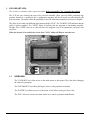


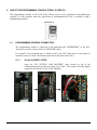


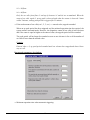
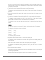
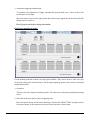
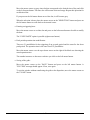
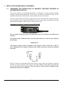

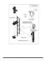


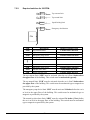


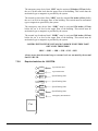
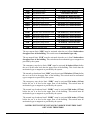

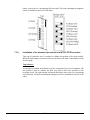
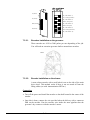


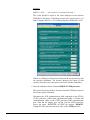


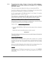


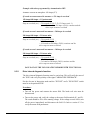


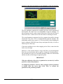


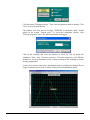


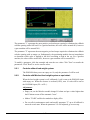


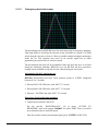


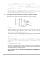
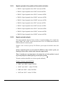


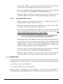
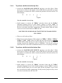


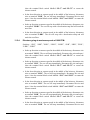
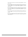


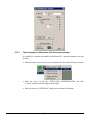


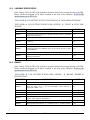


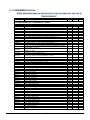
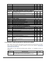


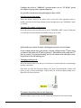


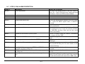


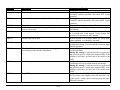


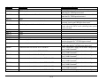


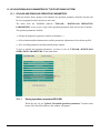

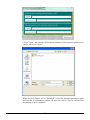


![CASBEE柏[戸建]LR1(PDF形式:1044KB)](http://vs1.manualzilla.com/store/data/006612808_2-5ed36873bbd1c6f331cc4a945d355d8b-150x150.png)