1
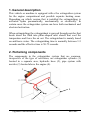
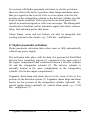
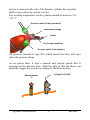
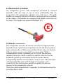
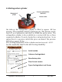
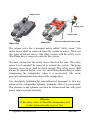
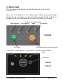
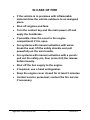
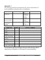
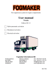
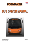
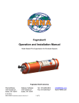
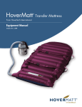
Fire extinguisher system for engine compartments User manual Contractor’s machinery / vehicles, tooling machines and special machines Edition 2011-2 Hydro pneumatic activation Mechanical activation Electrical activation Fogmaker International AB Postal address: Box 8005 350 08 Växjö SWEDEN Delivery address: Sandvägen 4 352 45 Växjö SWEDEN Tel: +46 470-77 22 00 Fax: +46 470-77 22 10 [email protected] www.fogmaker.com Part no. 8013-002 1. General description This vehicle or machine is equipped with a fire extinguisher system for the engine compartment and possible separate heating areas. Depending on which version that is installed the extinguishing is activated hydro pneumatically, mechanically or electrically. In certain cases the extinguisher system can have both mechanical and electrical activation. When extinguishing the extinguishant is sprayed through nozzles that break down the fluid into pillar-shaped mist clouds that cool the temperature and force the air out. The extinguishant is mainly based on antifreeze water. The extinguishing time is normally between 3-5 seconds and the effective time is 50-75 seconds. 2. Pertaining components The components in the extinguisher system that are common, irrespective of the type of activation, are extinguisher cylinder (1) located in a separate area, hydraulic hose (2), pipe system with nozzles (3) located above the engine (4). 1 2 4 3 Fogmaker International AB 2 8013-002 For systems with hydro pneumatic activation or electric activation there are often in the driver’s position alarm lamps and alarm sirens that give signals in the event of a fire or as an option, warn for low pressure in the extinguisher cylinder or the detector cylinder or in the event of smoke emission. There may also be an alarm panel with optical or acoustical signals or with voice messages. The alarm panel can also have functions such as automatic engine shut down, releaser delay, fuel and main power shut down. Alarm lamps, sirens and test buttons can also be integrated into existing systems in the vehicle, e.g., CAN bus – multiplexer. 2.1 Hydro pneumatic activation Hydro pneumatic activation takes place semi or fully automatically without any power supply. The activation takes place with the help of a pressurized fluid-filled detector hose containing polymer (1) mounted in the upper part of the engine compartment and connected between a detector cylinder (2) and the extinguisher cylinder (3). The detector cylinder is normally located in the same compartment as the extinguisher cylinder. (Not in the engine compartment!) Fogmaker alarm lamp and alarm buzzer in the event of fire or low pressure in the detection system (5), Fogmaker alarm lamp and alarm buzzer for low pressure in the extinguisher cylinder (optional) (5), optical smoke alarm (optional) (6), vehicle alarm panel e.g.,. CAN bus – multiplexer (7). Fogmaker International AB 3 8013-002 N2 H2O 3 1 6 5 2 7 5´ In the event of fire the detector hose bursts. When the pressure drop in the detection system has fallen to approx 10 bar a valve on the extinguisher cylinder is activated and the system is released. The pressure switch on the detector cylinder sends an alarm to the driver position. With a semiautomatic system, depending on the version that has been installed, either the vehicle contact key shall be turned off or the handbrake pulled on or the ladder lowered in order that the extinguishing shall be activated in the event of a fire. The activation is delayed until this point with the help of a magnetic valve connected to the detector hose and this maintains the detector pressure to the extinguisher cylinder. (Note the vehicle manufacturer’s appendix for information about the activation that is used) On delivery of the system the detector cylinder shows approx 20-24 bar, and is filled with detector fluid and a propellant. The propellant consists of nitrogen gas. The pressure can be read off on a manometer and shall be within the green sector. If the pressure falls below 14bar which means too low a system pressure the pressure switch sends an alarm, the same alarm as with a fire. As an option there is a detector cylinder with an extra pressure switch that sends an alarm if the pressure falls below 5 bar which means that the Fogmaker International AB 4 8013-002 system is released with a fire. The detector cylinder has a tap that shall be open when the system is active. The working temperature for the cylinder should be between -30 / +65 °C. Pressure switch 14 bar (standard) Manometer/Gauge Outlet Tap (in open position) Pressure switch 5 bar (option) All pressure switches is type NO, which means that they will open when the pressure drops. As an option there is also a manual and electric punch that is mounted on the detector hose. With the help of this the driver can manually trigger the system by cutting off the detector hose. Voltage 12-30 VDC Manual power F Fogmaker International AB 5 8013-002 2.2 Mechanical activation An extinguisher system with mechanical activation is released manually with the help of one or more pull-handles that are connected to the extinguisher cylinder valve with wires. The pullhandles are normally located in the driver position and on the outside of the vehicle. The handles are equipped with shackle locks that can be sealed. The handles are marked with labels (E). E 2.3 Electric activation The extinguisher system with electric activation is triggered either manually from a push button normally located in the driver position, semi automatically or fully automatically with the help of a detector cable or smoke sensors connected to an alarm panel. With a semiautomatic system, depending on the version that has been installed, either the vehicle contact key shall be turned off or the handbrake pulled on or the ladder lowered in order that the extinguishing shall be activated in the event of a fire. The activation is delayed until this point with the help of a magnetic valve connected to the detector hose and this maintains the detector pressure to the extinguisher cylinder. (Note the vehicle manufacturer’s appendix for information about the activation that is used). Fogmaker International AB 6 8013-002 2.4 Extinguisher cylinder Pressure switch 80 bar (optional) Manometer / gauge Release valve On delivery the extinguisher cylinder is filled to approx 105 bar pressure. The propellant consists of nitrogen gas. The pressure can be read off on a manometer and shall be within the green sector. The extinguisher cylinder is also available in a version with two or three connected cylinders. It can be located in a red protection box. As an option there is a pressure switch that gives an alarm if the pressure falls below approx 80 bar. The working temperature of the cylinder must not exceed + 65°C! See the round blue label for the anti freezing durability. Serial number Volume of extinguishant Manufactory date Time for next service Type of extinguishant, anti freeze Fogmaker International AB 7 8013-002 Safety screw Safety valve Cover screw New valve Older valve Hole for safety and cover screw The release valve has a transport safety called “safety screw”; the safety screw shall be removed when the system is active. There are two types of release valves. One older version with the safety screw fitted from above, remove to activate the system. The new version has the safety screw fitted on the side. The safety screw is red and shall be removed to activate the system. The green (shorter) cover screw shall be fitted instead. The safety screw shall always be inserted before a service, installation/dismantling or when transporting the extinguisher when it is pressurized. The screw prevents unintentional activation of the extinguisher. It is absolutely forbidden for non-authorized personnel to take any action on the extinguisher cylinder, primarily when it is pressurized. The pressure in the cylinder can then be released and can with great power injure a person seriously. Observe If the safety screw is fitted the extinguisher will not be deployed in the event of fire! Fogmaker International AB 8 8013-002 3. Alarm test The fire alarm shall always be tested before the work period commences. Press the Test button on the alarm panel. When pressed all light should be lit and alarm sound should be heard. If the vehicle is equipped with external alarm devices this will also be activated. Power indicator Indicator for semi automatic mode Error indicator Fire indicator 1746-050 Test button Fire indicator Power indicator Override button for engine shut down Error indicator Indicator for semi automatic mode Test button 1746-01 1745-01 Fogmaker International AB 9 8013-002 4. In the event of a fire 4.1 Vehicles without delayed engine shut down In case of fire, red and yellow error indicator will light up, built-in summer and any external alarm devices will be activated. If no fire has occurred and the system has not been triggered it indicates that there is too low a pressure in the extinguisher cylinder or the detector cylinder. Contact service personnel/workshop immediately. 4.2 Vehicles with delayed engine shut down Vehicles with alarm panel 1746-050 may be equipped with delayed engine shut down, contact the vehicle manufacturer or installer for info if uncertain. In case of fire the engine will shut down after approximately 10 s if not the Override button is pressed. The Override button will delay the engine shut down another 10s when released, to be able to move the vehicle from a dangerous location, for example a tunnel. Red fire indicator will flash as long as the engine is running; when engine is shut down it gives constant red light. Yellow error indicator, built-in summer and any external alarm devices will be activated. If the engine is shut down by the engine shut down function but needs to be restarted, press and hold the Override button and start the engine. Observe that there is a big risk of re-ignition and severe damages to the engine and vehicle if the engine is started directly after or during an engine fire. Fogmaker International AB 10 8013-002 IN CASE OF FIRE If the vehicle is in premises with inflammable material drive the vehicle outdoors to an assigned place. Shut off engines and fans. Turn the contact key and the main power off and apply the handbrake. If possible close the cover to the engine compartment if it is open. For systems with manual activation with wires: break the seal, lift the safety shackle and pull powerfully on the wire handle. For systems with manual activation with a punch: pull out the safety pin, then press (hit) the release button heavily. Shut off the fuel supply to the engine. If required, use a hand extinguisher. Keep the engine cover closed for at least 5 minutes. Contact service personnel; contact the fire service if necessary. Fogmaker International AB 11 8013-002 5. Low pressure alarm In the event of an alarm for low pressure in the detector cylinder or extinguisher cylinder (yellow light) contact service personnel. 6. Action after a fire The fire alarm will sound until the alarm is actively shut off. This is done by contacting authorized service personnel. For systems with Fogmaker Alarm panel 1746-050 the fire alarm can be muted by pressing and holding the Test button for approx. 10s. All other Fogmaker Alarms demand that the cables to the pressure switches are bridged. Do not start the vehicle before the cause of the fire has been established and corrected. The extinguishant does not normally affect the function of the engine. Starting difficulties can however occur for diesel engines since the extinguishant contains water. It is worth considering that the extinguishant can cause corrosion damage if the engine is not run within a short time after the fire. For the sake of safety the engine should be protected by filling a little oil and turning over the engine a couple of revolutions with the starter motor. In order to avoid corrosion on metal parts and unwanted short circuiting in the electrical system sanitation shall be carried out as soon as possible. This is done by rinsing with fresh water, preferably with high pressure. Use also some form of alkaline washing fluid, otherwise a film that collects dirt can remain. Fogmaker International AB 12 8013-002 7. Daily inspection of the extinguisher system Check that possible lamps for low pressure in the extinguisher cylinder or detector cylinder are not lit. Check that the pressure in the extinguisher cylinder and the detector cylinder is within the green sector on the manometers. Control is discontinued for the pressure switches on the detector and extinguisher cylinders. 8. Annual control The extinguisher system shall be controlled once a year by authorized personnel in accordance with the inspection report. See service manual for detailed instruction and detailed form. 9. 5 year service and 10 year overhaul Every fifth year the extinguishant shall be exchanged due to the characteristics of the product. Every tenth year the extinguisher cylinder shall undergo an overhaul where the extinguisher cylinder will be disassembled and checked for wear and damages. 5 year service and 10 year overhaul may only be carried out by authorized personnel. Fogmaker International AB 13 8013-002 Appendix 1 The following shall be documented by the vehicle manufacturer or by the installation technician after an installation: Registration no. Installation date Installation technician Person, company Pressure (Bar) on delivery Pressure (Bar) on delivery Chassis no. Serial no. detector cylinder Serial no. extinguisher cylinder Inspection Year 1 Year 2 Year 3 Year 4 Year 5 Revision Year 6 Year 7 Year 8 Year 9 Year 10 Revision Date Person, Company In order that the guarantee shall apply, this page and the first page shall be copied and sent to Fogmaker. (See first page for contact information). Fogmaker International AB 14 8013-002 Fogmaker International AB 15 8013-002 Fogmaker International AB Postal address: Box 8005 350 08 Växjö Sweden Delivery address: Sandvägen 4 352 45 Växjö Sweden Fogmaker International AB 16 Tel: +46 470-77 22 00 Fax: +46 470-77 22 10 [email protected] www.fogmaker.com 8013-002