1
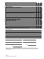
Fogmaker® Service Manual Water Based Fire Suppression System for Enclosed Spaces Fogmaker North America Post Address: Delivery Address: 150 Gordon Dr 150 Gordon Dr Exton, PA 19341 Exton, PA 19341 9/30/13 8011-002 Service Manual – Rev C Tel: 610-265-3610 Fax: 610-265-8327 [email protected] www.FMNA.net WARNING The safety screw must always be installed in the release valve during transport, installation and service. When the safety screw and protection plates are removed, the suppressing agent in the Fogmaker unit can be discharged. The release valve must not be removed when the system is pressurized. If the release valve or any of the nipples or connectors in the system are removed when the system is pressurized, the suppressing agent can be discharged unintentionally, resulting in serious personal injury. Note that only components from Fogmaker® may be used. If other components are used, Fogmaker® will not guarantee the system function. Components in this manual marked with an asterisk (*) are not UL listed. Control Plan for the Suppression Unit The suppression unit shall be serviced at least semiannually by qualified, trained, and authorized personnel according to the Control Plan in this Service Manual. Every fifth year the piston accumulator (PA) shall be serviced and the suppression fluid shall be replaced. Every tenth year the PA will need to be rebuilt and hydrostatic pressure tested. The service of the system may only be performed by authorized personnel. Control Plan for Weekly Inspection A visual inspection of the system components is to be performed every week to ensure that the suppression unit is not leaking and has not sustained damage. Any repairs are to be completed by authorized personnel. Control Plan for Daily Inspection Confirm that the piston accumulator is charged by confirming that the indicator for the pressure gauge is located in the green swept area. For hydro pneumatic activation units, the indicator for the pressure gauge located on the detection cylinder shall also be located in the green swept area. The pressures do not need to be checked if the PA and the detection cylinder have the electronic monitoring* option. Control Plan for Semi‐Annual Service 1. Piston Accumulator / Detection Cylinder 1.1 Control for Mounting/Vibration Damage to the Piston Accumulator Visually inspect all mounting components for any damage to the piston accumulator and the suppression unit’s peripheral equipment. Also confirm that there are no indications of mechanical damage or damage due to vibration. 1.2 Control of the Protecting Box / Labels Visually inspect the condition of the protecting box to confirm that it is protecting the piston accumulator satisfactorily and that the mounting components and assemblies are intact. Visually inspect the labels and markings on the suppression unit to confirm that they are legible and visible. 9/30/13 8011-002 Service Manual – Rev C Replace the markings and labels with new ones if required. Confirm that the date of installation is less than 5 years from the date of manufacture. If the suppression unit is older than 5 years, perform the 5 year service. 1.3 Control for Leakage / Corrosion Visually inspect the suppression unit to confirm there is no leakage or indications of corrosion/ corrosion deposits located on the piston accumulator couplings, connections, and release valves. 1.4 Change of Service Interval Label / Control of Gauge Pressure Upon completion of the service inspection, update the service interval label information by attaching a new label with the correct month towards the arrow. Check the location of the indicators on the pressure gauges and note their positions on the inspection report. Note! The indicator on the pressure gauges for the piston accumulator and the detection cylinder should be located in the green swept area. If deviations occur, contact Fogmaker® or an authorized service provider. 2. Maintenance of Mechanical Cable Activation Components* 2.1 Before servicing, ensure the safety screw is installed in the release valve. Check that all the releases are sealed and that all the cables run easily without damage to the wire cables or the release valve components that can affect their function. Remove the protective cover on the release valve and free the wire cable so that it is possible to test its function. Spray lubricating oil CRC 5‐56 or the equivalent on the valve mechanism. Restore the wires and valve as well as sealing the releaser again. 3. Suppression Unit / Hydraulic Hose (Distribution System) 3.1 Control for Vibration Damage / Wear Visually inspect the suppression unit to confirm that there is no damage or wear to any of the hoses or the piping and components in the unit. 3.2 Control for Braces (Clamps), Tightness Visually inspect and confirm that braces do not display any indications of wear and that the piping system components are tightened to the requirements in the Operation and Installation Manual, number 8010‐0022. Confirm that all connections are tight. If leakage is suspected, the suppressing unit must be test pressurized according to the Installation Manual. 9/30/13 8011-002 Service Manual – Rev C 3.3 Control for Protective Covers for Nozzles Visually confirm that the protective covers for the nozzles are in position and are clean. If not, inspect nozzle before replacing with a new cover. Nozzle covers for .8L flow nozzles are yellow in color; covers for 1.2L flow nozzles are orange in color. 3.4 Control for Breakages / Cracks on Hydraulic Hoses Visually check hydraulic hoses for wear, deterioration, cracks, or breakages that can result in faults or leakage when the suppression unit is operated. 4. Detection System 4.1 Control for Detection Gas Cylinder / Detection Fluid Cylinder Check the condition and the fixture of the cylinder. The gauge pressure shall be in the green area. If not, contact Fogmaker® for consultation. 4.2 Control for Detection Tube / Clamps Check the routing and fixture of the detection tube so that no wear or other damage can occur. Check that nothing is rubbing the detection tubing through the protective coil. 4.3 Control for Damage to Protective Tube / Protective Coil (Spiral) 4.4 Check that there is no wear, pinching, or other damage to the protective tube or protective coil and that it is secure according to the Operation and Installation Manual. Check clamps for wear and tightness. Control for Labels on the Detection Tube Confirm that the red‐colored “FIRE DETECTOR” labels (Part # FM‐8206) are legible and located on the detection tube. Replace these labels if they are damaged or missing. 5. Alarm Panel / Alarm Device / Cables* 5.1 Check for Slackness, Breakage, and Cracks Check that there is no excessive slackness in the cables and that all joints and cables are undamaged. 5.2 Function Test / Fire Simulation – For Electronically Monitored Units* Confirm that the green indicator light is on. Refer to the Alarm Panel Manual for instructions on testing to confirm that the contact switches on the detection cylinder and the piston accumulator will indicate a fire condition. 9/30/13 8011-002 Service Manual – Rev C 6. Other Items 6.1 6.2 Control for Suppression Unit Enclosure Check to ensure that the enclosure is unchanged since the last inspection. Installation and Operation Manual / Owner’s Manual A copy of the Operation and Installation Manual (number 8010‐0022 Rev F) and a copy of the Owner’s Manual (number 8012‐001 Rev A) is to accompany each unit at all times. Replace if missing or incomplete. Activation Labels / Control Labels 6.3 Confirm that the activation/control labels are visible and legible in accordance with the instructions in the Operation and Installation Manual. 6.4 Control if Safety Screw is Not Engaged into the Release Valve Confirm that the detection system for the Hydro Pneumatic Activation option is activated and that the safety screw is removed from the Piston Accumulator Release Valve. Refer to the Operation and Installation Manual for activation/deactivation instructions. 9/30/13 8011-002 Service Manual – Rev C FMNA Fire Suppression System __ Inspection Report __ Installation Report __ Service Report Service Technician Order # Date Work Site Customer City, State, Zip # of Nozzles ** Piston Accumulator Serial # PA Gauge Reading Contact Name Detector Serial # Address Contact Phone End User Vehicle # Vehicle Mfg. 1 Piston Accumulator (PA) 1.1 Control Fixture/ Vibration Damage Detector Gauge Reading Vehicle Year/Model ** Contact FMNA Engineering or OEM for correct number & placement of nozzles YES NO NA YES NO NA YES NO NA Are all mounting locations of the PA intact with no signs of wear or breakage? 1.2 Control Protection Box / Labels Is the protection box intact with no signs of wear or breakage? Are all labels visible and legible? 1.3 Control Leakage / Corrosion Is there any indication of leakage or corrosion around the PA couplings/valve/connections? 1.4 Change of Service Interval Label / Control of Gauge Pressure Is the service interval date label changed for next inspection? For annual inspections only, is the annual inspection label replaced as required for warranty? Is the pressure gauge indicating in the green area on the PA and is the pressure reading recorded on this form? Is the safety screw for the release valve located on the PA removed and is the system active? 2 Cable Activation / Electric Activation* BEFORE PERFORMING ANY WORK ON ACTIVATION, RE-INSERT THE SAFETY SCREW! 2.1 Checking the Cable or Electric Activation* Is the manual or electric punch* properly installed and properly connected? For cable activation, inspect the handle lever for proper sealing and/or damage. Lubricate cables and handle assembly, if applicable. Check cables and harness connections on electrical punch*, if applicable. Confirm the pull pin can be removed on the manual button. 3 Hydraulic Hose (Distribution System) 3.1 Control for Vibration Damage / Wear Are there any indications of damage/wear on any of the hoses or pipes in the system? Are the stainless pressure lines free of kinks and nicks? 3.2 Control for Braces (Clamps), Tightness Are all braces or clamps secure per the installation instructions and in good condition? Are all connections tightened per the requirements in the installation instructions? 3.3 Control for Protective Covers / Proper Positioning of Nozzles Are the proper number of nozzles installed? Are all nozzles properly positioned per First Article Inspection and free of obstructions? Are the protective covers for the nozzles in position and clean? If not, replace with new ones. 9/30/13 8011-002 Service Manual – Rev C 3.4 Control for Breakages / Cracks on Hydraulic Hoses Are all hoses secure and in good condition? Are all hoses and tubing connections tight with no possibility for leaks? 4 Detection System 4.1 Control for Detection Gas Cylinder / Detection Fluid Cylinder YES NO NA YES NO NA YES NO NA Are all mounting locations of the detection bottle intact with no signs of wear or damage? Is the pressure gauge indicating in the green area on the detection bottle and is the pressure reading recorded on this form? 4.2 Control for Detection Tube / Clamps Is the routing and fixture of the detection tube free from wear or other damage? Is there any area of the detection tubing unprotected? Is the detection tube free of abrasions and secured, and does nothing contact the tube through the protective coil, etc.? Are all tubing connections tight with no possibility for leaks? 4.3 Control for Damage to Protective Tube / Protective Coil (Spiral) Is there any wear, pinching, or other damage to the protective tube or protective coil? Is the protective coil secure and are the ends properly bent according to the Installation Manual? 4.4 Control for Labels on the Detection Tube Are the Red “FIRE DETECTOR” labels clearly visible on the detection tube? Replace as needed. 5 Alarm Panel* / Alarm Device* / Cables* 5.1 Check for Slackness / Breakage / Cracks Is there any slack in the cables and are all joints/cables undamaged? 5.2 Function Test / Fire Simulation Is the green light illuminated on the control panel and does there appear to be no evidence of tampering? Has the control panel been tested per the instructions on the panel? 6 Other Is all electrical wiring intact and showing no sign of wear or damage? Are all control labels up to date and visible? Check if customer would like the system manuals sent electronically and notify customer service. Additional Comments: Service Tech (Printed) Customer Name (Printed) Signature Customer Signature Date Company Date Note: It is the customer's responsibility to ensure that all service checks are performed in accordance to Fogmaker North America's guidelines as indicated in the Operation and Installation Manual. Services and/or maintenance must be performed by a Fogmaker-trained, certified technician. It is the responsibility of the customer to correct any problems as indicated by this document to ensure the proper function of the system. 9/30/13 8011-002 Service Manual – Rev C