1
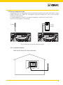
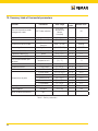
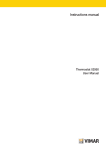
Instructions manual 02906 GSM thermostat Installer Manual Table of Contents 1. GSM thermostat 02906……………………………………………………………………………………………… 2 2. Field of application………………………………………………………………………………………………… 2 3. Installation…………………………………………………………………………………………………………… 2 4. Connections…………………………………………………………………………………………………………… 4 4.1 Relay connection ………………………………………………………………………………………………… 4 4.2 External temperature probe……………………………………………………………………………………… 5 5. GSM function………………………………………………………………………………………………………… 7 4.1 Fitting and replacing the SIM card……………………………………………………………………………… 7 6. Switching on a resetting parameters……………………………………………………………………………… 9 7. Display……………………………………………………………………………………………………………… 7.1 Functions of the buttons ……………………………………………………………………………………… 7.2 Symbols………………………………………………………………………………………………………… 7.3 Ecometer……………………………………………………………………………………………………… 7.4 Locking the interface via PIN………………………………………………………………………………… 10 11 11 12 12 8. Operating mode…………………………………………………………………………………………………… 8.1 Switched off (OFF) …………………………………………………………………………………………… 8.2 Manual………………………………………………………………………………………………………… 8.3 Away…………………………………………………………………………………………………………… 8.4 Nighttime reduction…………………………………………………………………………………………… 8.5 Antifreeze……………………………………………………………………………………………………… 13 13 14 15 16 17 9. Settings menu……………………………………………………………………………………………………… 9.1 Operating mode setting……………………………………………………………………………………… 9.2 Heating/air-conditioning setting……………………………………………………………………………… 9.3 Temperature set point setting………………………………………………………………………………… 18 18 19 19 9.3.1 Comfort temperature……………………………………………………………………………………………… 9.3.2 Away temperature………………………………………………………………………………………………… 9.3.3 Antifreeze temperature…………………………………………………………………………………………… 9.3.4 Nighttime reduction thermal delta……………………………………………………………………………… 9.3.5 User settable thermal delta……………………………………………………………………………………… 9.3.6 Hysteresis of the device…………………………………………………………………………………………… 19 20 20 20 20 20 9.4 Unit of measurement setting………………………………………………………………………………… 20 9.5 Calibration setting……………………………………………………………………………………………… 21 9.6 External probe setting………………………………………………………………………………………… 21 9.7 OnOff/PID setting……………………………………………………………………………………………… 21 9.8 Buzzer setting………………………………………………………………………………………………… 22 9.9 Standby brightness level setting……………………………………………………………………………… 22 9.10 GSM settings…………………………………………………………………………………………………… 23 9.11 Info……………………………………………………………………………………………………………… 23 9.12 Lock/unlock PIN setting……………………………………………………………………………………… 23 10. Summary table of thermostat parameters…………………………………………………………………… 24 11. Cleaning the device………………………………………………………………………………………………… 25 12. Installation rules…………………………………………………………………………………………………… 25 13. Regulatory compliance………………………………………………………………………………………… 25 1 1. 02906 GSM thermostat Mains powered wall-mounted thermostat with interface with capacitive keys, with GSM remote control function. Equipped with user-friendly functions to facilitate energy saving. Designed to control heating and air-conditioning via C, NC, NO relay output. Input for management of an external temperature probe (e.g. art. 02965). 2. Field of application This device is designed to control room temperature by acting on the control circuit of the burner or circulation pump (heating) or on the control circuit of the air conditioner (air conditioning), ensuring an ideal temperature. The graphical user interface, thanks to special views, facilitates system management helping the user to operate while maintaining a state of energy saving. The thermostat has a GSM communicator for remote control, making it ideal for installation in second homes. 3. Installation The appliance must be installed on a wall at a height of 1.5 m off the floor in a suitable position for correctly detecting the ambient temperature. It must not be installed in niches, behind doors and curtains or in areas affected by sources of heat or atmospheric factors. It can be installed directly on a wall or on 2 and 3 module back boxes (see figures 1 to 7). It should be used in dry, dust-free places at a temperature between 0 °C and +40 °C 1 2 m 6m ~ 0V z 2350/60H L N O C N NC ~ A 5(2) 06 029 2 0V 23 1.C IN LY ITA 0 –T4 DE MA 3 4 m 6m ~ 0V z 2350/60H L N O C N NC V~ 0 23 )A 1.C E MAD 5(2 IN LY ITA 0 –T4 06 029 e2 VI 5 MA R Pb Sp A 6 ~ 230V 0Hz 50/6 0V~ N NO C C N 23 A 5(2) C 1. DE MA IN m 6m L LY ITA 0 –T4 ~ 230V 0Hz 50/6 0V~ N NO C C N 23 A 5(2) C 1. e2 V A IM R Pb Sp DE MA IN 6 0290 LY ITA e2 0 –T4 A m 6m L VI MA R Pb Sp A 6 0290 7 ~ 230VHz 50/60 ~ 230V C C N N NO A 5(2) C 1. DE MA IN L 6 mm 1 LY ITA –T40 6 0290 e2 VI MA R Pb Sp A click 2 3 4. Connections 4.1 Relay connection L N N art. 02965 T C U1 C NC NO N L e 2 Pb VIMAR SpA Fig. 1 - Connections with circulation pumps, burners and solenoid valves L N APRE-OPENS OUVERTE-ÖFFNEN ABRIR-ΑΝΟΙΓΜΑ N art. 02965 T C CHIUDE-CLOSES FERMÉE-SCHLIESSEN CERRAR-ΚΛΕΙΣΙΜΟ U1 C NC NO N L e 2 Pb VIMAR SpA Fig. 2 - Connections with motorized valves 4 4.2 External temperature probe Depending on how it is configured, the external temperature probe can be used to accomplish several functions (see par. 9.6); it does NOT have polarity so you can connect the 2 wires in the 2 terminals without any particular order. It is recommended to use the NTC 10k beta 3900 probe (art. 02965-20432-19432-14432). The typical wiring diagram is the following: N art. 02965 T C art. 20432 art. 19432 art. 14432 C NC NO N L e 2 Pb VIMAR SpA C NC NO N L e 2 Pb Fig. 3: Connecting the external temperature probe VIMAR SpA 4.2.1 Installation examples: 02695 used to display the outside temperature 5 02695 used for adjustment (of a remote environment) 02695 used for limiting the temperature of underfloor heating IMPORTANT: During installation, take care not to damage the insulation of the probe while laying the screed. Perform the installation in such a way that the probe is accessible for any maintenance work. 6 5. GSM function By sending and receiving SMSs with the appropriate encryption, the thermostat can be switched on, off and queried for viewing data on the room and it can perform various other functions; interaction with the device for remote control is via the By-clima smartphone app that automatically creates the encrypted SMSs. Using these features you can then: • Set the operating parameters of the thermostat. • Send commands. • Query the thermostat to know the current operating status. • Receive previously configured and enabled alarm notifications. • Receive from the thermostat any SMSs that have not been recognized as command SMSs. Command and monitoring SMSs are generated by the By-clima App while voice calls, reading and therefore interpreting incoming SMSs must be managed manually by the user with the standard smartphone functions. More in detail, the functions associated with GSM mode via SMS or via voice calls are: • Thermostat management = setting the operating mode (Off, Antifreeze, Away, Manual, Nighttime reduction). • Thermostat configuration = programming all the temperature control parameters that can also be set locally by the thermostat and configuration of all the functions of the GSM module that instead cannot be programmed locally. • Requesting the current operating status of the thermostat (for all the various types). • Notification of alarms for power supply voltage failure/restoration (only if configured and paired with users saved in the contacts list). • Notification of technical alarms for exceeding the temperature thresholds (only if configured, enabled and paired with users saved in the contacts list). • Receiving SMSs sent by the thermostat as they are not recognized as being in compliance with the communication protocol (only if configured and paired with users saved in the contacts list). Generally, the configuration commands do not require confirmation SMSs as instead is the case for the monitoring commands; so, in order to have confirmation on successfully setting a parameter, you need to query the thermostat about its status. Otherwise, all the command operations that, for example, change the active temperature control mode, will generate an SMS for notification and confirmation of the operation. Using the "phone call" function, which generates a voice call from a recorded user, you can obtain information on the general status of the device. Associated to the voice call, you can also switch the operating state, in the following way: • In heating mode: - from Manual to Antifreeze - from any other mode to Manual • In air-conditioning mode: - from Manual to OFF - from any other mode to Manual Also in this case a report of the general status of the GSM device is sent to the caller number. 7 5.1 Fitting and replacing the SIM card The thermostat can be used with a traditional SIM card (ID-000 format) for voice / SMS traffic; data SIMs cannot be used for operating the device . To install the SIM card: • Disable the PIN code from the SIM card (install the SIM in a mobile phone and when switching on disable the PIN code prompt). • Turn off the power supply to the thermostat 02906. • Remove the front panel by inserting a screwdriver into the slot in the bottom and pushing the release tab upwards and, at the same time, pull out the front of the product. • Insert the SIM card into the SIM holder in the rear of the front panel you have just removed. • Fit the front panel back into its original position by hooking it onto the mounting tabs located on the upper side of the part on the wall and then closing the lower part. Finally, power up the thermostat. 1 2 N OPE CK LO 3 4 N OPE CK LO • The icon will show the correct installation and the quality of the GSM network: blinking: switch-on phase (if the icon is still flashing after a few minutes, it means that there is an ERROR so it is necessary to check the SIM card) : GSM signal not present or insufficient : GSM signal barely sufficient (up to 20%) : GSM signal from 20% up to 50% : GSM signal from 50% up to 80% : optimum GSM signal (over 80%) 8 6. Switching on and resetting parameters When switching on, in the first 3 seconds of power-up the thermostat displays the firmware version. Fig. 4: Start up screen If in this phase you touch the parameters: icon, a screen appears on the display where you can reset the device Fig. 5: Parameter reset screen By confirming with , ALL the device parameters (temperature setpoint, heating/air-conditioning mode, unit of measurement, etc.) and ALL GSM function settings (phone numbers, SMS, etc.) will be restored to the default values. WARNING This operation is not undoable. If you wish to reset only the GSM settings, refer to paragraph 9.10.2. 9 7. Display The touchscreen display allows you to control the system using the following buttons and icons: A B L I H G F E Fig. 6: Graphical interface and buttons A: GSM network signal B: Operating mode C: Away D: Confirm E-F: Menu navigation and setting parameters G: Back H: Nighttime reduction I: Settings menu L: Ring indicating consumption level and energy savings indicator 10 D C 7.1 Functions of the buttons : increases the numerical values. When it "disappears" from the display it means that the value cannot be increased any more. : decreases the numerical values. When it "disappears" from the display it means that the value cannot be decreased any more. : during navigation, it scrolls through the available menus to the right. If it "disappears" then you have arrived at the last of the items that can be scrolled. : during navigation, it scrolls through the available menus to the left. If it "disappears" then you have arrived at the last of the elements that can be scrolled. : confirms the selected option (activates the submenu if there is one or displays the next parameter/digit). After each confirmation, the display shows the icon for approximately 1 s. : back (or cancel) exits the current screen/menu and returns to the previous one without saving any changes. In menus with changes to multiple digits it lets you go back to change the previous digit. N.B. The field/value being edited is highlighted by the field/value itself flashing. 7.2Symbols Depending on the different operating modes, the following icons could also be displayed: : GSM network signal status : Calibration : Away : Manual (ON) : Nighttime reduction : Antifreeze : Switched off (OFF) : Air conditioning : Heating : Confirm : Eco (saving) 11 7.3Ecometer Ring for the level of consumption Energy saving indicator Fig. 7: Set of ECOMETER icons On the left-hand side of the display there is a set of icons called the "ECOMETER" that provide an overview of the expected consumption as an aid to energy saving. The information displayed is based on a consumption forecast obtained by comparing the currently set temperature setpoint and the estimated average consumption (which therefore has nothing to do with the current room temperature). • The consumption level ring graphically indicates the expected level of consumption. If this level is less than half, it means that there will be a saving compared to the conventional average consumption; vice versa, if the level exceeds half, the expected consumption will be higher than the conventional average. • The energy saving indicator indicates whether the currently set setpoint will allow obtaining savings with respect to the conventional average consumption. 7.4 Locking the interface via PIN The thermostat lets you set a password (see par. 9.12) which inhibits any change to the operating mode (eg switching from Manual to OFF), limits setting the temperature values and, more generally, blocks access to the configuration menu. This feature is useful to prevent the thermostat being used by unauthorized persons: the device prompts you to enter the PIN. Fig. 8: Locking with PIN 12 8. Operating mode The thermostat 02906 is able to adjust the temperature according to the following operating modes: • Switched off (OFF): switches the system off without making any adjustments • Manual (ON): lets you set the required temperature set-point manually • Away: is a mode that lets you set the set-point in order to achieve significant energy savings during periods when the user is away •N ighttime reduction: this mode, which can be activated locally, is useful for changing the manual adjustment set point in the hours of nighttime operation. • Antifreeze: used to set a minimum temperature level to avoid damage to pipework or prevent the temperature from falling below a safety level. The operating mode is selected via the SETTINGS menu (see chap. 9). 8.1 Switched off (OFF) With this mode on, the thermostat is turned off and you cannot make any adjustments; in this case, the icon is displayed above the temperature indicator. When the thermostat is OFF, you cannot perform any operations other than accessing the configuration menu. Fig. 9: Typical screen for OFF mode For heating-only systems this mode is typically used in the summer. 13 8.2 Manual (ON) This is the "traditional" operating mode. The thermostat controls the room temperature and takes it to the value set by the user (manual adjustment setpoint). Fig. 10: Typical screen for Manual mode The set point can always be changed via or . In the course of setting, the set point flashes and the circular ring fills up accordingly; this gives an indication of the expected consumption as a function of the set point you are setting: Fig. 11: Manual set point setting The selection is confirmed by touching . The and icons in the lower right corner indicate whether the system is operating in heating or air-conditioning mode respectively (icon illuminated = system on). 14 8.3Away This mode is useful to achieve energy savings quickly and effectively whenever the user leaves the regulated room. In "Away" mode the system makes the adjustment according to the "away temperature" setpoint (see para. 9.3.1). The Away mode can only be activated in manual mode by touching . The display will show the "away temperature" setpoint for approximately 2 seconds: Fig. 12: Input in away mode showing the away temperature Activation of this mode is identified by the icon above the temperature indicator: Fig. 13: Away Mode To exit and return to Manual mode touch the button again. 15 8.4 Nighttime reduction This is the typical mode to use at night to reduce system consumption significantly. In "Nighttime reduction" mode the device reduces the consumption of the system, taking the room temperature to a lower value (or higher, if on air-conditioning) than the Manual mode by degrees (see par. 9.3.3). The "Nighttime reduction" function is done from Manual mode by touching . The display will show the "nighttime reduction" setpoint for approximately 2 seconds: Fig. 14: Input in Nighttime Reduction mode showing the reduction set point Activation of this mode is identified by the icon above the temperature indicator: Fig. 15: Nighttime reduction mode To exit and return to Manual mode touch 16 again. 8.5Antifreeze This mode, which can only be activated when the system is operating in heating mode, lets you set a minimum temperature value ( setpoint) to avoid damage to the pipework or to keep it from falling below a certain safety level when you are away for lengthy periods in the winter. The "antifreeze" mode is activated directly from the Settings menu (see par. 9.1). Once activated, antifreeze mode is identified by the icon above the temperature indicator. Fig. 16: Antifreeze mode 17 9. Settings menu From the settings menu you can configure all the features of the thermostat. On the main screen (see Fig. 6) tap the icon. From the main menu, using and will display the following (flashing) symbols in succession, which provide access to the corresponding submenus: 1. operating mode setting 2. and 3. air-conditioning/heating setting temperature setpoint setting 4. unit of measurement setting 5. calibration setting 6. external temperature probe setting (shown only when the probe is connected) 7. OnOff/PID temperature control algorithm setting 8. 9. buzzer setting brightness of the display on Standby setting 10. GSM function setting 11. device info 12. lock/unlock PIN setting Touching opens the submenu and then the flashing highlights the parameters of the submenu. 9.1 Operating mode setting This menu is used to select the operating mode of the device: • Manual • • Using 18 Off Antifreeze (only if the thermostat is set on "heating") and select the required mode and confirm with . 9.2 Heating/air-conditioning setting This menu lets you set the operation of the device depending on the season (winter/summer): • heating • air-conditioning Using and select the required operation and confirm with . 9.3 Temperature set point setting This menu lets you set the temperatures and hystereses necessary for defining the temperature control set-point used in the different operating modes. In particular, you can have setpoints for: 1. and 2. and 3. and 4. temperature of the Away mode * temperature of the Antifreeze mode thermal delta in Nighttime reduction mode * thermal delta with thermostat inhibited by PIN 5. temperature differential of the device (only if in OnOff adjustment mode) 6. and : external probe alarm temperature (if fitted and configured) * WARNING: Depending on the mode the thermostat is in (heating or air-conditioning), setting this setpoint acts only on the value associated with the current mode highlighted by the or icon. After then changing the setpoints of the current mode in succession, change the mode and set all the setpoints corresponding to it. 9.3.1 Away temperature This menu, via or , lets you increase/decrease the value of the away temperature . The away temperature, preset by the user, is an intermediate temperature between that of Manual and Antifreeze mode, geared to obtain substantial energy savings during periods when the user is away. 19 9.3.2 Antifreeze temperature This menu, via or , lets you increase/decrease the value of the antifreeze temper- ature . Antifreeze mode is used to set a minimum temperature level to avoid damage to the pipework or keep the room temperature from falling below a safety level (see par. 8.5). 9.3.3 Nighttime reduction thermal delta This menu, via and , lets you set the difference between the Nighttime temperature and the temperature set in Manual mode. The hysteresis is an increase/decrease in temperature that is applied to the Manual setting; the thermal delta value is identical both in heating mode and in air-conditioning mode with the only difference being that in the former case it causes a decrease in the set point while in the latter one it determines an increase. 9.3.4 User settable thermal delta This menu, via and , lets you set the range of values within which the user can adjust the temperature when the menus are inhibited after setting a PIN. In this condition, the control temperature is fixed and therefore cannot be changed; with instead, the user can modify the temperature within a certain range. 9.3.5 Hysteresis of the device This menu, via and , lets you set the temperature range of the heating/air-conditioning system between "ON" and "OFF". This value can also be changed via the submenu for ON/OFF operation. The parameter cannot be changed if the thermostat is set as PID operation. For example: Heating, with setpoint on 20.0°C, : 0.5°C 20.5 (off), 19.9 (on) 9.3.6 External probe alarm temperature The menu, via or , lets you set the temperature limit (read by the external probe) at which the thermostat switches off the heating system and triggers an alarm (useful to protect underfloor systems against overheating). To view this menu, the external temperature probe must be wired set as a "limitation". 9.4 Unit of measurement setting • The menu lets you set the unit of measurement used for the temperature (°C or °F) Using 20 and select the required unit of measurement and confirm with . 9.5 Calibration setting This menu lets you "calibrate" the temperature read by the thermostat. Using or , you can add or subtract (at intervals of 0.1°) a fixed amount from the temperature detected by the thermostat to make it equal, for example, to that of a sample thermometer. CAUTION: For correct calibration it is recommended to wait until the thermostat has been on for at least 1 hour in a room at constant temperature. Tap to confirm your choice. 9.6 External probe setting This menu lets you configure how to use the external temperature probe (installed according to the instructions in par. 4 .2) Using or , you can select the following options: • OFF: the external probe (although physically present) is ignored by the device. • Adjustment (the measured temperature flashes): by enabling this function, the thermostat will regulate the temperature of the environment based ONLY on the temperature detected by the external probe (the temperature measured by the thermostat is ignored). The temperature shown on the display will be that of the external probe identified by the icon. • Display (the temperature measured by the thermostat and that of the external probe are shown alternately on the display): the external probe is only used to display the temperature in another environment . On standby the display will alternate views of the internal temperature (measured by the thermostat) and external temperature (measured by the probe) and identifiable by the icon. • Limitation (the icon flashes): mode used for systems with underfloor heating. In the associated submenu you set the limitation temperature, that is the one, read by the external probe immersed in the screed, that is considered an excessive temperature. If this threshold temperature is reached the thermostat turns off the heating system and displays the alarm as long as the condition that generated it remains. At the end of this condition, the thermostat resumes its normal operation. Tap to confirm your choice. 9.7 OnOff/PID setting This menu lets you select the way in which the ambient temperature will be controlled. Using or , you can select the following options: • (OnOff control): this is the traditional "threshold" control so that, on exceeding the set temperature increased by (vice versa for air-conditioning), the heating is switched off to then be turned back on when the room temperature drops below the set temperature. The value can be set directly via the submenu that follows this selection. 21 • (P.I.D. control): this is an evolved algorithm that is able to keep the temperature in the environment more stable, increasing comfort; this algorithm switches the system on and off appropriately so there will be a gradual increase or decrease in the thermal (or refrigerating) power of the system itself. To take full advantage of its performance it needs to be suitably calibrated according to the type of environment and heating system; in the light of this, the following parameters must be set via the submenus that follow this selection: • (breadth of adjustment range): starting from the set temperature, Tb is the temperature range in which the heating power goes from 0% to 100%. For example: with the temperature (for heating) set to 20.0°C and Tb=4.0°C, the thermostat activates the heating system on 100% when T.ambient is <= 16.0°C; as this temperature increases, the system power is consequently lowered down to 0% when the ambient temperature reaches 20°C. The value of Tb must be set consistently with the thermal capacity of the system; in general, it is recommended to use small values of Tb for environments with a good level of thermal insulation and vice versa. • (system cycle time): this is the time in which a cycle of regulation is completed; the shorter this time, the better the regulation but the temperature control system is under greater stress. This parameter setting is thus the result of a compromise between the accuracy of the regulator and the load on the system; in general, the rule is that Tb can be that much higher (and therefore put fewer demands on the system), the slower the system or the larger the environment to regulate. Tap to confirm your choice. 9.8 Buzzer setting This menu lets you enable/disable the acoustic signals of the thermostat; if it is disabled there will no longer be any sound when you touch the buttons or in cases of confirmation/error. Whereas, in the event of an alarm, the sound signal will always be guaranteed. Using and select “ON” or “OFF” and confirm with . 9.9 Standby brightness level setting The menu lets you set the brightness level when the thermostat is in standby. Using or you can select one of the folloiwng levels with gradually increasing brightness: •OFF • 1, 2, 3, 4, 5, 6, 7 While scrolling through the values, when the selection stops on a certain level, the brightness of the display will, for approximately 2 s, take on the brightness corresponding to the selected level in order to allow the user to check the visual effect. Finally, tap 22 to confirm your choice. 9.10 GSM settings All the GSM functions are set exclusively via a special smartphone App which communicates by SMS with the thermostat and not via the actual thermostat; the latter is used to enable all the functions described in paragraphs 9.10.1 and 9.10.2. 9.10.1 Switching on/off the GSM radio This option is used to switch the GSM radio transmitter on of off (for example, to check that the thermostat is set only locally and that it cannot be remotely enabled/modified by any other configured mobile phone). Using and select “ON” or “OFF” and confirm with . 9.10.2 GSM parameter resetting This option is used to cancel ALL the GSM function parameters; it will specifically cancel: • the GSM security code; • alarm thresholds and enabling (these will be restored to the default value); • the GSM network parameters; • the set language (which will be restored to the default language); • all the phone numbers used by the thermostat to send messages (no more messages will be sent). 9.11 Info This menu lets you view information related to the thermostat and reset the device. Using or è you can select: • : displays the number of hours that the thermostat relay has been on (the same as the number of hours of operation of the system). The counter can be reset, by a simple prolonged touch in the centre of the display (for example at changes in season to differentiate between heating and air-conditioning). • displays the software version of the device. 9.12 Lock/unlock PIN setting This menu lets you add/change the password to inhibit use of the thermostat. Using or each set digit. you can set the three digits of the PIN one at a time and then confirm N.B. Having set the PIN return to the main menu; the PIN is active after around 30 s. If you wish to have free access to the thermostat (so without it prompting you for a password) it is sufficient to set the PIN to "000". If you lose or forget the PIN, to release the thermostat you must perform a full reset (see chapter 6). 23 10. Summary table of thermostat parameters Parameters Value range Resolution Default value EXT Probe selection [Off, View, Temperature Control, Limitation] - Off Nighttime Reduction δR (red. offset) [1,..,6]°C, 0.1°C 4°C Limitation TL (Temp. limit) [30,..,50]°C 0.1°C 35°C Selection TempCtrl [Heat., Air-con.] - Heating Algorithm [ON/OFF, PID] - ON/OFF δT (Differential) [0.1,..,1]°C 0.1°C 0.2°C Function External temperature probe management mode Temperature control mode Control algorithm Hysteresis (ON/OFF) Proportional band (PID) Band [0.5,..,5]°C 0.1°C 1°C Adjustment period (PID) Period [10,..,30] minutes 1 min 20 min Temperature unit [°C , °F] - °C Unit of measurement (temperature) User thermal delta ΔTu (Differential) [0,..,2]°C 0.1°C 0°C Temperature offset TE (Offset temp.) [0,..,±3]°C 0.1°C 0°C PIN number Temperature set-point Backlight Audio feedback Reset to default parameters PIN [000,..,999] 1 000 T0 (Away-Heat.) [TG, 10..35]°C 0.1°C 16°C T0 (Away-Aircon.) [10,..,35,OFF]°C 0.1°C 29°C TM (Manual-Heat.) [10,..,35]°C 0.1°C 18°C TM (Manual-Aircon.) [10,..,35]°C 0.1°C 26°C TG (Antifreeze) [4,..,10]°C 0.1°C 5°C BLLVL [0,..,7] 1 3 BuzzerEn [OFF, ON] ON rSEt - - Table 1: Device parameters 24 - 11. Cleaning the device The device features a touchscreen display with capacitive buttons and therefore requires you to be gentle during the cleaning phase. Avoid using aggressive products. Clean the display with a special cloth for cleaning lenses. 12. Installation rules Installation should be carried out in compliance with the current regulations regarding the installation of electrical systems in the country where the products are installed. 13. Standard compliance LV directive. EMC directive. Standards EN 60730-2-9. 25 Viale Vicenza, 14 - 36063 Marostica VI - Italy Tel. +39 0424 488 600 - Fax (Italy) +39 0424 488 188 Fax (Export) +39 0424 488 709 www.vimar.com 02906 installer 01 1407 VIMAR - Marostica - Italy