1
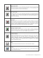
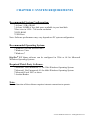
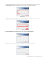
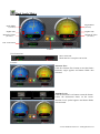
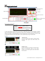
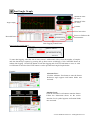
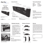
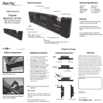
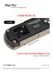
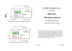
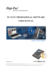
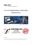
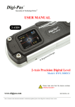
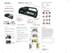
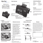
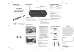
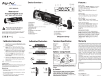
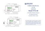
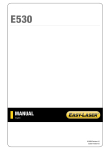
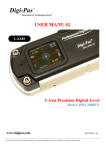
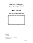
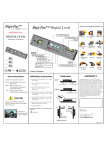
Digi-Pas®
Innovation & Technology Driven™
PC SYNC PROFESSIONAL SOFTWARE
USER MANUAL
Model: DWL8500XY
REVISION 2.00
www.digipas.com
Note: Contents in this instruction manual is continuously updated, please check Digi-Pas website for latest version.
INTELLECTUAL PROPERTY
This manual contains propriety information, which is protected by copyrights. All rights
are reserved. No part of this manual may be photocopied, reproduced, redistributed or
translated to another language without prior written consent of JSB TECH Company.
The information in this manual was correct at the time of printing, stored in CD or
uploaded in the Company website. However, JSB TECH will continue to improve
products and reserves the rights to change specification and maintenance procedures at
any time without prior notice.
The PC Sync software uses the National Instruments™ Measurement Studio* for
certain user interface tools and measurement applications.
Digi-Pas® Products were manufactured under ISO9001 & ISO14001
standards, tested to comply by the followings certification bodies:
®
®
Digi-Pas , the Digi-Pas logo are registered trademarks of JSB TECH Pte Ltd. © 2013 DIGIPAS USA LLC. All
Rights Reserved.
*National Instrument™ logo is the trademarks of National Instruments Corporation. Microsoft is the registered
trademarks of Microsoft Corporation.
TABLE OF CONTENT
CHAPTER 1: GENERAL OVERVIEW
- Interface Overview
- Software Features
CHAPTER 2: SYSTEM REQUIREMENTS
CHAPTER 3: GETTING STARTED
- Installation of DWL8500XY PC Sync
- Synchronization with USB
- Synchronization with Bluetooth
CHAPTER 4: FEATURES INTERFACE AND SETTING
- Single Angle Meter
- Dual Angle Meter
- Dual Axis Bull's Eye
- Single Angle Graph
- Dual Angle Graph
- VibroMeter
- 3D Surface Geometry Graph
© 2013 DIGIPAS USA LLC. All Rights Reserved.
CHAPTER 1: GENERAL OVERVIEW
Interface Overview
Sync Option
Function
Toolbar
Buttons
Communication
LED
Screen
Display
Communication
Status
Sync Option
Communication Status
Communication LED
Function Toolbar
Screen Display
To select the synchronization mode (via USB or Bluetooth)
To show the communication status between PC, device and DigiPas® Security
Dongle.
To indicate the device is connected to the software
Contains buttons with different functions.
To display the graphic user interface.
Software Features
Single Angle Meter
This feature allows user to view single-axis angle/levelling measurement in numerical
and graphical display i.e. arcsec and mm/M units concurrently on PC monitor via USB
or wireless Bluetooth connectivity.
Dual Angle Meter
This feature allows user to view dual-axis angle/levelling measurement simultaneously
in numerical and graphical in arcsec and mm/M units concurrently on PC monitor via
USB or wireless Bluetooth connectivity.
Smart Bull's Eye
This feature allows user to view and record dual-axis angle/levelling measurement
simultaneously in graphical "Bull's eye", line graphs, Numeric format on arcsec and
mm/M units. User may define several parameters for data capturing. The numerical
data can be saved in Excel format for further analysis.
© 2013 DIGIPAS USA LLC. All Rights Reserved.
Single Angle Graph
This feature allows user to view, track and record real-time single-axis angle/levelling
measurement readings in numerical and graphical forms (i.e. arcsec and mm/M). User
may define parameters for numerical data capturing.
Dual Angle Graph
This feature allows user to view, track and record real-time 2-axis angle measurement
(i.e. a plane or set of coordinates) angle/levelling measurement readings in numerical
and graphical forms (i.e. arcsec and mm/M). User may define parameters for
numerical data capturing.
VibroMeter
This feature allows user to monitor low frequency vibration patterns in line graph.
User may define several parameters for capturing vibration data. Vibration monitoring
on precision machine/equipment/instrument and also their surrounding floor condition
to identify vibration magnitude/pattern that affects accuracy performance influencing
production yield, scraps reduction and sharp-quality image capturing.
3D Surface Geometry Graph
This feature allows user to perform 3D surface flatness geometry measurement,
profiling and characterization. The 3D visual graph and its corresponding 3D numeric
data can be saved and stored in Excel file for further analysis & record.
Commission Report
Numerical and graphical data can be collected and stored in PC in the form of
Commissioning Report files especially useful for accountability purpose and
references as historical records for each machine/equipment installation, setup and
preventive maintenance requirements. Multiple machines characteristics for levelling
and vibration conditions can be stored and used for comparison in next planned
preventive maintenance activity.
Help
To open the Instruction Manual for the device and its Instruction manual.
About
This feature allows user to check the current PC Sync version and the firmware
version of the device in sync.
© 2013 DIGIPAS USA LLC. All Rights Reserved.
CHAPTER 2: SYSTEM REQUIREMENTS
Recommended System Configuration:
* At least 1 GB of RAM
* At least 100MB of free disk space available in your hard disk
* Best view in 1024 × 768 screen resolution
* DVD-ROM
* USB Ports
Note: Software performance may vary depends on PC system configuration.
Recommended Operating System:
* Windows XP with Service Pack 3
* Windows Vista
* Windows 7
Digi-Pas® PC Sync software can be configured in 32bit or 64 bit Mircosoft
Windows Operating Systems.
Required Third-Party Software:
* Microsoft .Net Framework 3.5 for 32bit Windows Operating System
* Microsoft .Net Framework 4.0 for 64bit Windows Operating System
* Microsoft Excel 2007 or above
* Acrobat Reader
Note:
Certain function of the software requires internet connection to operate.
© 2013 DIGIPAS USA LLC. All Rights Reserved.
CHAPTER 3: GETTING STARTED
Installation of DWL8500XY PC Sync
1. Insert DWL8500XY PC Sync DVD into your DVD drive. The following screen pops up
automatically. Select the Adobe Acrobat Reader or .Net Framework button when your
computer does not have the software. It needs internet connection to complete the installation.
Next, click the PC Sync installation button according to your Window Operating System
(32bit or 64 bit).
Installation Step 1
2. Welcome screen appears. Click " Next " to proceed the installation.
Installation Step 2
3. License Agreement screen appears. Click "I Agree" after reading through and accepting the
agreement and then click " Next " to proceed the installation.
Installation Step 3
© 2013 DIGIPAS USA LLC. All Rights Reserved.
4. Customer Information screen appears. Enter your Name and Organization. Key in Device’s
Serial Number attached in the DVD box. Click "Next" to proceed the installation.
Installation Step 4
5. Installation folder screen appears. Use the installation folder as default unless you want to
change the location. Click "Next" to proceed the installation.
Installation Step 5
6. Confirm Installation screen appears. Click "Next" to proceed the installation.
Installation Step 6
7. Installation Complete screen appears. Click "Close" to complete the installation.
Installation Step 7
© 2013 DIGIPAS USA LLC. All Rights Reserved.
Synchronization by Using USB Connectivity
Check the DWL8500XY Bluetooth device synchronization mode. By default, device setting is set to USB
mode. To check or change the mode setting:
1. Press "MODE" button and select "PC SYNC" icon to access the Synchronization
Setting page.
2. Select USB icon then press "Mode" button to activate it.
Note: Status indicates the device is in USB or Bluetooth mode.
3. The device is required to turn OFF by pressing "ON/OFF" button and thereafter
please turn ON the device again in order to activate the newly set
Synchronization mode.
4. Double click the PC Sync icon on the desktop and connect DWL8500XY device with your computer
via USB cable and insert the DigiPas® Security Dongle to the computer. Select the Sync Option with
USB and click " SELECT" button. All function toolbar buttons are turned on and the status bar shows
"Device Connected and DigiPas® Security Dongle is found". The DWL8500XY PC Sync is now
ready for use.
Interface of DWL8500XY PC Sync when it is ready to use
© 2013 DIGIPAS USA LLC. All Rights Reserved.
Synchronization by Using Bluetooth Connectivity
First, check the DWL8500XY Bluetooth device synchronization mode. By default, device setting is set to
USB mode. To check or change the mode setting:
1. Press "MODE" button and select "PC SYNC" icon to access the Synchronization
Setting page.
2. Select Bluetooth icon then press "Mode" button to activate it.
Note: Status indicates the device is in USB or Bluetooth mode.
Status: USB Active
3. The device is required to turn OFF by pressing "ON/OFF" button and thereafter
please turn ON the device again in order to activate the Synchronization mode.
4. Bluetooth logo appears on the device screen (at top-right corner). The device
setting is now completed. User can proceed to synchronise the DWL8500XY
device with the PC Sync software.
5. Activate your computer's Bluetooth and plug in the dongle to the USB port. Then, select the Sync
Option with BLUETOOTH (i.e. located at top-right corner of your PC monitor) and click " SELECT"
button.
6. "Discover Bluetooth Device" button is shown on PC monitor. Select the button to search for the
DWL8500XYBluetooth device.
7. Bluetooth devices is shown at the drop down box. Select the device with the serial number indicated as
shown on the drop down box and press "Connect to Bluetooth Device button" to establish the wireless
connection.
8. When the connection is established successfully, all function toolbar buttons are turned on and the
status bar shows "Device Connected and DigiPas® Security Dongle is found". The DWL8500XY PC
Sync is now connected to the Device and ready for use.
© 2013 DIGIPAS USA LLC. All Rights Reserved.
CHAPTER 4: FEATURES INTERFACE AND SETTING
Single Angle Meter
Unit Conversion
Angle Meter
(X-Axis)
Higher Side
Features
Measured Value
Blinking indicates measurement is in progress
Unit Conversion:
Unit Conversion:
Untick the box to stop the conversion.
Features:
Alternate Zero:
Click the Alternate Zero button to start the feature.
Reference angle appears and button blinks once
activated.
Alternate Zero
Instructions for Absolute Level
Absolute Level:
Click the Absolute Level button to start the feature.
Follow the instructions shows on the screen.
Absolute Level symbol appears and button blinks
once activated.
Absolute Level
© 2013 DIGIPAS USA LLC. All Rights Reserved.
Dual Angle Meter
Angle Meter
(X-Axis)
Angle Meter
(Y-Axis)
Higher Side
Higher Side
Measured Value
(Y-Axis)
Measured Value
(X-Axis)
Unit Conversion
Features
Unit Conversion:
Unit Conversion:
Untick the box to stop the conversion.
Features:
Alternate Zero:
Click the Alternate Zero button to start the feature.
Reference angle appears and button blinks once
activated.
Alternate Zero
Instructions for Absolute Level
Absolute Level:
Click the Absolute Level button to start the feature.
Follow the instructions shows on the screen.
Absolute Level symbol appears and button blinks
once activated.
Absolute Level
© 2013 DIGIPAS USA LLC. All Rights Reserved.
Smart Bull's Eyes
Measured Value
(X-Axis)
Measured Value
(Y-Axis)
Features
Angle Graph
Higher Side
Measured Value:
X. : X-Axis
Y. : Y-Axis
Unit Conversion
Freeze or Unfreeze
the measurement
Data Logging
Control Panel
Bubble Meter
Recorded Data
Unit Conversion:
Click the unit conversion button to change to other units
(arcsec, mm/M).
Data Logging Control Panel:
To start data logging, select the unit of time (second / millisecond). Next, select the number of samples
and time duration per capture by pressing the up down arrow accordingly. Click CAPTURE button to
initiate data logging. Click STOP button to halt data logging and click CLEAR button to erase or click
SAVE button to store the data. EXIT button is used to quit the Smart Bull's Eyes window.
© 2013 DIGIPAS USA LLC. All Rights Reserved.
Single Angle Graph
Measured Value
(X- Axis)
Angle Graph
Features
Unit Conversion
Recorded Data
Freeze or Unfreeze the
measurement
Data Logging
Control Panel
Data Logging Control Panel:
To start data logging, select the unit of time (second / millisecond). Next, select the number of samples
and time duration per capture by pressing the up down arrow accordingly. Click CAPTURE button to
initiate data logging. Click STOP button to halt data logging and click CLEAR button to erase or click
SAVE button to store the data. EXIT button is used to quit the Single Angle Graph window.
Features:
Alternate Zero:
Click the Alternate Zero button to start the feature.
Reference angle appears and button blinks once
activated.
Absolute Level:
Click the Absolute Level button to start the feature.
Follow the instructions shows on the screen.
Absolute Level symbol appears and button blinks
once activated.
© 2013 DIGIPAS USA LLC. All Rights Reserved.
Dual Angle Graph
Measured Value
(X-Axis)
Measured Value
(Y-Axis)
Angle Graph
Features
Unit Conversion
Freeze or Unfreeze the
measurement
Recorded Data
Data Logging Control Panel
Data Logging Control Panel:
To start data logging, select the unit of time (second / millisecond). Next, select the number of samples
and time duration per capture by pressing the up down arrow accordingly. Click CAPTURE button to
initiate data logging. Click STOP button to halt data logging and click CLEAR button to erase or click
SAVE button to store the data. EXIT button is used to quit the Dual Angle Graph window.
Features:
Alternate Zero:
Click the Alternate Zero button to start the feature.
Reference angle appears and button blinks once
activated.
Absolute Level:
Click the Absolute Level button to start the feature.
Follow the instructions shows on the screen.
Absolute Level symbol appears and button blinks
once activated.
© 2013 DIGIPAS USA LLC. All Rights Reserved.
VibroMeter
Auto Center
Signal Level Control
Time Interval Control
Vibration Graph
Freeze or Unfreeze the
measurement
Recording
Panel
Over-limit Setting
Recorded
Data
Over-limit Data
Data Logging
Control Panel
Time Interval Control
To adjust the time interval (Horizontal Scale) for the vibration graph.
Scale 0: 10 seconds (default)
Scale 5: 5 seconds
Signal Level Control
To amplify the measured magnitude of vibration.
Scale 1: Original measured vibration value
Scale 2: Double the measured vibration value
Auto Center
To auto adjust the vertical scale of the graph and set the zero relative gravity at the center of the graph.
Data Logging Control Panel:
To start data logging, select the unit of time (second / millisecond). Next, select the number of samples
and time duration per capture by pressing the up down arrow accordingly. Click CAPTURE button to
initiate data logging. Click STOP button to halt data logging and click CLEAR button to erase or click
SAVE button to store the data. EXIT button is used to quit the VibroMeter window.
© 2013 DIGIPAS USA LLC. All Rights Reserved.
3D Surface Geometry Graph
Guidelines
Save Button
Scaling of
Z-Axis
Surface
Dimension
Number of
Grids
Reset
Button
3D Surface Geometry Graph
Surface Dimension
Measure the dimension (width and length) of the surface. Insert the
measured value into the column and click enter.
Number of Grids
Choose the surface to be divided into small grids automatically or
manually. Draw the grids on the surface.
Measurement
Put the device in dual axis mode. Place the device on the grid and press
the respective button. Repeat this step until all the grid are measured.
3D Surface Geometry Grpah
The 3D geometry graph is ready. Tune the knot to adjust the scale of Zaxis. Click save button to save the graph and numerical data into excel
file.
© 2013 DIGIPAS USA LLC. All Rights Reserved.