1
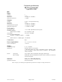
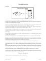
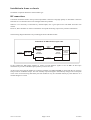
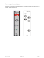
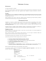
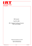
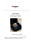
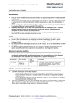
I R T Electronics Pty Ltd A.B.N. 35 000 832 575
26 Hotham Parade, ARTARMON N.S.W. 2064 AUSTRALIA
National: Phone: (02) 9439 3744
Fax: (02) 9439 7439
International:
+61 2 9439 3744
+61 2 9439 7439
Email: [email protected]
Web: www.irtelectronics.com
IRT Eurocard
Type RWA-3085
RF Distribution Amplifier
for
70 MHz IF signals
Designed and manufactured in Australia
IRT can be found on the Internet at:
http://www.irtelectronics.com
3085-rwa.ib.rev4.doc
Page 1 of 10
16/10/2007
IRT Eurocard
Type RWA-3085
RF Distribution Amplifier
for
70 MHz IF Signals
Instruction Book
Table of Contents
Section
Page
General description
Technical specifications
Technical description
Internal adjustments
Installation
RF connections
Front & rear panel connector diagrams
Maintenance & storage
Warranty & service
Equipment return
Drawing index
3
4
5
5
6
7
8
9
9
9
10
This instruction book applies to units later than S/N 9900000.
3085-rwa.ib.rev4.doc
Page 2 of 10
16/10/2007
General description
The RWA-3085 has been designed to provide distribution and amplification of signals in 70 MHz IF systems.
An input attenuator with a 20 dB range provides gain control to optimise signal levels at the output.
This allows adjustment from –5 dB to +15 dB from input to output.
The amplifier will tolerate a wide range of input levels to a maximum of 0 dBm and a maximum output level of +10
dBm.
The frequency response of the amplifier is tailored to give optimum low noise amplification to 70 MHz IF signals
used in satellite distribution.
The amplifier finds special application in the provision of redundant path generation for fibre optic links from
satellite sites to control centres.
The amplifier may also be used to distribute one satellite feed to numerous down converters and decoders for
viewing multiple channels from one satellite receiving dish.
The RWA-3085 may be mounted in standard IRT Eurocard frames alongside other Eurocard modules including
switchers and fibre optic transmitters or receivers for 70 MHz IF signals.
Standard features:
•
•
•
•
40 - 100 MHz frequency response optimised for use in 70 MHz IF distribution.
Very low noise.
-5 - +15 dB variable gain control.
Output monitoring on front panel.
Equipment provided:
Standard:
RWA-3085 RF distribution amplifier module.
RWA-3085 Rear connector assembly
Accessories available:FR-700 Eurocard module mounting frame
Mounts up to 12 Eurocard modules and one PT-700
Dual AC power supply side by side in 134 mm of
standard rack space (3 Rack Units).
FRU-1030 1 RU chassis conversion/PSU
Converts Eurocards to a 1 rack unit format. The
FRU-1030 can be fitted with either one or two
Eurocards in a horizontal side by side format. A
single AC power supply is included to power the
cards.
TME-6 Eurocard extender board.
Instruction Book.
3085-rwa.ib.rev4.doc
Page 3 of 10
16/10/2007
Technical specifications
IRT Eurocard module
Type RWA-3085
RF:
Input:
Number
Impedance
Return loss
Maximum input level
1.
75 Ω.
> 14 dB (40 - 100 MHz).
> 0 dBm.
Outputs:
Number
Impedance
Return loss
Isolation between outputs
Maximum output level
4 plus 1 x front panel monitoring.
75 Ω.
> 14 dB (40 - 100 MHz).
> 20 dB (40 - 100 MHz).
>+10 dBm at 70 MHz.
Performance:
Input/output gain
Frequency response
(Referenced to 70 MHz)
Group delay
Two tone intermodulation IP3
(65 MHz + 75 MHz test signals)
Noise
(Referenced to a –10 dBm signal)
-5 to +15 dB. Adjustable from front panel.
Connectors:
BNC
Power requirements:
14 – 0 - 14 Vac or ±15 Vdc.
<10.5 VA.
Power consumption
40 to 100 MHz ±1 dB.
±2 ns (40 - 100 MHz).
> +20 dBm.
-110 dBc/Hz.
Other:
Temperature range
Mechanical
0 - 45° C ambient.
Mounts in IRT 19" rack chassis.
* Maximum number per frame is dependent on PSU capability, other
types of modules in same frame and air circulation - See installation
section of manual.
Finish:
Grey enamel, silk-screened black lettering & red IRT logo.
Detachable silk-screened PCB with direct mount connectors to Eurocard
and external signals.
Front panel
Rear assembly
Dimensions
Dimensions
Optional accessories
6 HP x 3 U x 220 mm IRT Eurocard.
30 mm x 3 U x 231 mm IRT Eurocard.
Instruction manual.
Due to our policy of continuing development these specifications are subject to change without notice.
3085-rwa.ib.rev4.doc
Page 4 of 10
16/10/2007
Technical description
Signal Path:
RWA-3085 Block Diagram
O/P 4
O/P 3
INPUT
SPLITTER
-7 dB
AMP
22 dB
O/P 2
O/P 1
ATTENUATOR
0 - 20 dB
MONITOR
The block diagram above shows the principal parts of the signal path for the RWA-3085.
The input signal is applied directly to the input variable attenuator module which has a characteristic impedance of
75 Ohms and a maximum attenuation of 20 dB.
The BGY67A wideband RF amplifier hybrid module that follows the attenuator has a fixed gain of approximately
22 dB (maximum 24 dB) resulting in a minimum gain of 2 dB above input level at its output.
The output of the amplifier feeds a passive splitter module with five output ports. The loss at any output is
approximately 7 dB, resulting in an overall system gain of from –5 dB to + 15 dB.
Four of the outputs are available on the rear of the amplifier and one on the front panel for monitoring purposes.
Note that this front panel output is no different to any other output in its characteristics.
Power supply:
The RWA-3085 is equipped with two AC rectifier circuits to take advantage of the redundant AC power supplies
provided in IRT’s 3 RU frames.
Filters FIL 1 to 4 and capacitors C1 to 4 provide EMC filtering between the power supply busses and the module.
Resistors F 1 to 4 provide fuse protection to the frames power supply busses in the event of a failure on the module.
Should these fail they should only be replaced by resistors of the same type and value or damage may result to the
module and may also effect the operation of other modules in the same frame.
The rectified power is filtered by capacitors C 5 to C 12 providing both high an d low frequency filtering.
The BGY67A hybrid amplifier module is the only active component in the RWA-3085. This amplifier requires a
single sided DC supply of +24 V, which is outside the range normally available from the frame’s AC power supply
buss.
In order to obtain this supply a DC-DC converter is employed. This converter may be damaged by overvoltage on
its input and so input protection is provided by the Zener diode ZD 1 and resistors R 1 & 2, which limit the input
voltage to 33 Volts.
The output of the DC-DC converter has additional filtering applied by the LC network of C 13 to 15 and L 1.
The front panel DC LED is fed from the 24 Vdc supply and thus gives a true indication of the whole power supply
operation and power being available to the amplifier module.
Internal adjustments
The RWA-3085 has no internal adjustments or user serviceable parts.
3085-rwa.ib.rev4.doc
Page 5 of 10
16/10/2007
Installation
Operational Safety:
WARNING
Operation of electronic equipment involves the use of voltages and currents that
may be dangerous to human life. Note that under certain conditions dangerous
potentials may exist in some circuits when power controls are in the OFF position.
Maintenance personnel should observe all safety regulations.
Do not make any adjustments inside equipment with power ON unless proper
precautions are observed. All internal adjustments should only be made by suitably
qualified personnel. All operational adjustments are available externally without the
need for removing covers or use of extender cards.
Pre-installation:
Handling:
This equipment may contain or be connected to static sensitive devices and proper static free handling precautions
should be observed.
Where individual circuit cards are stored, they should be placed in antistatic bags. Proper antistatic procedures
should be followed when inserting or removing cards from these bags.
Power:
AC mains supply:
Ensure that operating voltage of unit and local supply voltage match and that correct rating
fuse is installed for local supply.
DC supply:
Ensure that the correct polarity is observed and that DC supply voltage is maintained within
the operating range specified.
Earthing:
The earth path is dependent on the type of frame selected. In every case particular care should be taken to ensure
that the frame is connected to earth for safety reasons. See frame manual for details.
Signal earth: For safety reasons a connection is made between signal earth and chassis earth. No attempt should be
made to break this connection.
3085-rwa.ib.rev4.doc
Page 6 of 10
16/10/2007
Installation in frame or chassis:
See details in separate manual for selected frame type.
RF connections:
Connection should be made to the input and output BNC connectors using high quality 75 Ohm BNC connectors
and cable so as to minimise return loss and signal reflection problems.
Whilst it is not necessary to terminate any unused outputs, this is good practice for both EMC and return loss
reasons.
However, there should be no need to terminate the front panel monitoring output in any normal circumstances.
The following diagram illustrates one possible application of the RWA-3085.
Redundant 70 MHz IF Fibre Optic Link
RWT-3085
70 MHz IF
Input
RWA-3085
Optical
Fibre
70 MHz IF
Optical
Transmitters
RWT-3085
RWR-3085
70 MHz IF
Optical
Receivers
Optical
Fibre
ZWR-3085RH
Auto or
manual
changeover
70 MHz IF
Output
RWR-3085
In this example the RWA-3085 amplifier is used to provide identical signals to two 70 MHz IF fibre optic
transmitters to provide a redundant optical pathway to the receive site.
At the receiver end a special, double rear connector assembly (type ZWR-3085RH) is used to link the two receivers
and provide one 70 MHz IF output. This rear assembly may be arranged to automatically change to the second path
in the event of a failure being detected by the main module or may be controlled remotely by other detectors or a
manual changeover switch.
3085-rwa.ib.rev4.doc
Page 7 of 10
16/10/2007
Front & rear panel connector diagrams
The following front panel and rear assembly drawings are not to scale and are intended to show relative positions of
connectors, indicators and controls only.
RWA-3085
RW A - 3 0 8 5
OUTPUTS
1
3
3
4
MON.
GAIN
DC
INPUT
N140
3085-rwa.ib.rev4.doc
Page 8 of 10
16/10/2007
Maintenance & storage
Maintenance:
No regular maintenance is required.
Care however should be taken to ensure that all connectors are kept clean and free from contamination of any kind.
This is especially important in fibre optic equipment where cleanliness of optical connections is critical to
performance.
Storage:
If the equipment is not to be used for an extended period, it is recommended the whole unit be placed in a sealed
plastic bag to prevent dust contamination. In areas of high humidity a suitably sized bag of silica gel should be
included to deter corrosion.
Where individual circuit cards are stored, they should be placed in antistatic bags. Proper antistatic procedures
should be followed when inserting or removing cards from these bags.
Warranty & Service
Equipment is covered by a limited warranty period of three years from date of first delivery unless contrary
conditions apply under a particular contract of supply. For situations when “No Fault Found” for repairs, a
minimum charge of 1 hour’s labour, at IRT’s current labour charge rate, will apply, whether the equipment is within
the warranty period or not.
Equipment warranty is limited to faults attributable to defects in original design or manufacture. Warranty on
components shall be extended by IRT only to the extent obtainable from the component supplier.
Equipment return:
Before arranging service, ensure that the fault is in the unit to be serviced and not in associated equipment. If
possible, confirm this by substitution.
Before returning equipment contact should be made with IRT or your local agent to determine whether the
equipment can be serviced in the field or should be returned for repair.
The equipment should be properly packed for return observing antistatic procedures.
The following information should accompany the unit to be returned:
1.
2.
3.
4.
5.
6.
7.
A fault report should be included indicating the nature of the fault
The operating conditions under which the fault initially occurred.
Any additional information, which may be of assistance in fault location and remedy.
A contact name and telephone and fax numbers.
Details of payment method for items not covered by warranty.
Full return address.
For situations when “No Fault Found” for repairs, a minimum charge of 1 hour’s labour will apply,
whether the equipment is within the warranty period or not. Contact IRT for current hourly rate.
Please note that all freight charges are the responsibility of the customer.
The equipment should be returned to the agent who originally supplied the equipment or, where this is not
possible, to IRT direct as follows.
Equipment Service
IRT Electronics Pty Ltd
26 Hotham Parade
ARTARMON
N.S.W.
2064
AUSTRALIA
Phone:
Email:
3085-rwa.ib.rev4.doc
61 2 9439 3744
[email protected]
Page 9 of 10
Fax:
61 2 9439 7439
16/10/2007
Drawing index
Drawing #
Sheet #
Description
804258
1
RWA-3085 IF splitter circuit schematic
3085-rwa.ib.rev4.doc
Page 10 of 10
16/10/2007
3
2
1
PCB 804259 ISS.2
J6
P1
26/AB
25/AB
23/AB
24/AB
22/AB
21/AB
1
1
C4
10n
1
C3
10n
C2
10n
C1
10n
1
P1
DSS306
FIL1
31/AB
29/AB
30/AB
DSS306
FIL2
2
DSS306
FIL3
DSS306
FIL4
3
3
3
3
2R2
F4
2R2
F3
2R2
F2
2R2
F1
1
1
DB2
DB106
DB1
DB106
3
3
C6
10n
C7
100n
C5
10n
ATTENUATOR
6R8
R2
6R8
R1
C11
10n
1500u
C9
C8
1500u
C10
10n
1N5364B
ZD1
1
100n
C17
C12
100n
BGY67A
AMP
2
1
VIN-
VIN+
PBB2A-24D12D
CONV
9
100n
2,3,7,8
5
C16
100n
C18
6
INPUT
6
4
4
6
1
2
2
2
2
11
-V
0V
+V
3
4
7
13
'DC'
14
PSC-5-1-75
C13
10n
5
SPL1
5
SPLITTER
MONITOR
1
2
2
1
+24V
JP1
0R0
L1
RFC
GRN
LD1
R3
2K7
15
16
12
8
4
1 10-06-1995
2 21-03-1999
Move attn. on pcb
+24V
Date:
K.N.
3-Oct-2001
Revision: 2
ENG. APP.
CHECKED
DRAWN
DO NOT COPY NOR
DISCLOSE TO ANY
THIRD PARTY
WITHOUT WRITTEN
CONSENT
10u
C15
1/AB
2/AB
3/AB
10/AB
13/AB
14/AB
15/AB
16/AB
18/AB
17/AB
19/AB
20/AB
27/AB
28/AB
32/AB
P1
4/AB
5/AB
6/AB
7/AB
8/AB
9/AB
12/AB
COPYRIGHT
C14
10n
P1
11/AB
RWA-3085
804258
Sheet
1 of 1
IF DISTRIBUTION AMPLIFIER
Drawing No.
Title
IRT Electronics Pty. Ltd.
ARTARMON NSW AUSTRALIA 2064
SCALE
N.T.S.
A3
SIZE
J2
O/P 1
J3
O/P 2
J4
O/P 3
J5
O/P 4