1
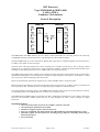
I R T Electronics Pty Ltd A.B.N. 35 000 832 575
26 Hotham Parade, ARTARMON N.S.W. 2064 AUSTRALIA
National: Phone: (02) 9439 3744
Fax: (02) 9439 7439
International:
+61 2 9439 3744
+61 2 9439 7439
Email: [email protected]
Web: www.irtelectronics.com
IRT Eurocard
Type MMM-4680 & MMX-4680
4 ASI to STM-1
Combiner / DeCombiner
Designed and manufactured in Australia
IRT can be found on the Internet at:
http://www.irtelectronics.com
4680-mmm & 4680-mmx.ib.rev3.doc
Page 1 of 11
18/12/2007
IRT Eurocard
Type MMM-4680 & MMX-4680
4 ASI to STM-1
Combiner / DeCombiner
Instruction Book
Table of Contents
Section
Page
Operational Safety
General Description
Technical Specifications
Configuration
Installation
Front and rear layouts
Maintenance & Storage
Warranty & Service
Equipment return
2
3
4
5
6
10
11
11
11
This instruction book applies to units later than S/N 0712015.
Operational Safety:
WARNING
Operation of electronic equipment involves the use of voltages and currents that
may be dangerous to human life. Note that under certain conditions dangerous
potentials may exist in some circuits when power controls are in the OFF position.
Maintenance personnel should observe all safety regulations.
Do not make any adjustments inside equipment with power ON unless proper
precautions are observed. All internal adjustments should only be made by suitably
qualified personnel. All operational adjustments are available externally without the
need for removing covers or use of extender cards.
4680-mmm & 4680-mmx.ib.rev3.doc
Page 2 of 11
18/12/2007
IRT Eurocard
Type MMM-4680 & MMX-4680
4 ASI to STM-1
Combiner / DeCombiner
General Description
MMM-4680
MMX-4680
ASI-1
ASI-1
Input
Output
ASI-2
Input
Mux
&
Signal
Processing
Processing
&
De-Mux
ASI-2
Output
2x
STM-1
STM-1
Outputs
Input
ASI-3
ASI-3
Input
Output
ASI-4
ASI-4
Input
Output
DATA
DATA
Input
Output
The MMM-4680 and MMX-4680 are part of a family of data transcoders for converting between the commonly
used MPEG2 Transport Stream formats for video distribution in the broadcast industry.
With the MMM-4680 up to four ASI and one RS232 data signal can be combined together and converted into a
155Mb/s G.703 (STM-1) electrical signal.
The sum of the ASI input payload rates can be anything up to 148 Mb/s. Inputs may be 188 or 204 byte packet
length, burst or continuous, and may have energy dispersal scrambling, interleaving and/or Reed Solomon bytes
included. An individual input may be up to 148Mb/s if the other inputs are unused.
The MMX-4680 separates the 155 Mb/s G.703 signal back into the original four ASI signals (at their original rates)
and the RS232 data signal. The ASI outputs are suitable for Single Frequency Network use, in that there is no data
rate conversion or PCR restamping of the ASI streams.
Inputs are automatically equalised for lengths of up to 250m of Belden 8281 or equivalent cable.
RS232 uni-directional data may also be sent on the same link. It can pass rates up to 38kb/s with any combination of
start/stop & parity bits. The data rate does not affect the payload available for the ASI streams.
Front panel indication and relay alarm on the MMM-4680 transmitter shows if there is an input data rate violation.
Corresponding alarm on the MMX-4680 receiver shows a loss of STM-1 input.
The MMM-4680 and MMX-4680 are designed to fit IRT’s standard Eurocard frames as well as IRT’s 4000 series
frame for use with IRT’s SNMP system and may be used alongside any other of IRT’s analogue or digital
Eurocards.
Standard features:
•
•
•
•
•
Up to 4 ASI and 1 Data stream on one 155 Mb/s (STM-1) G.703 link
Automatic Input equalisation up to 250m
Suitable for Single Frequency Network (SFN) use
Recovers transmitted ASI signal without any added PCR jitter and with minimal user setup.
Maintains original ASI rate, packet size & coding (energy dispersal scrambling, interleaving or
Reed Solomon bytes)
• Eurocard format
4680-mmm & 4680-mmx.ib.rev3.doc
Page 3 of 11
18/12/2007
Technical Specifications
MMM-4680:
Inputs:
Type 1
Maximum Data Rate
4 x ASI-C 75Ω, 800 mVp-p, BNC connector.
Combined 148 Mb/s
Type 2
RS232 Uni directional data input.
Output:
Type
Electrical Characteristics
Data Rate
Alarm Output:
MAJOR
MINOR
1 x G.703, 75Ω BNC connector.
CMI encoded.
155.52 Mb/s.
Open circuit on sum of ASI input payload rates in excess of maximum
allowable 148Mb/s, or loss of power.
Open circuit on no valid input ASI streams present, or loss of power.
MMX-4680:
Input:
Type
Electrical Characteristics
Data Rate
1 x G.703, 75Ω BNC connector.
CMI encoded.
155.52 Mb/s.
Outputs:
Type 1
Data Rate
Type 2
4 x ASI-C 75Ω, 800 mVp-p, BNC connector.
same as MMM-4680 input rate.
RS232 Uni directional data output.
Alarm Output:
MAJOR
MINOR
Power Requirements
Power consumption
Open circuit on no valid STM-1 input present, or loss of power.
Open circuit on no valid output ASI streams present, or loss of power.
28 Vac CT (14-0-14) or ±16 Vdc.
6 VA.
Other
Temperature range
Mechanical
Finish
Front panel
Rear assembly
Dimensions
0 - 50° C ambient.
Suitable for mounting in IRT 19" rack chassis with input, output and power
connections on the rear panel.
Grey, silk-screened black lettering & red IRT logo.
Detachable silk-screened PCB with direct mount connectors to Eurocard and
external signals.
6 HP x 3 U x 220 mm IRT Eurocard.
Due to our policy of continuing development, these specifications are subject to change without notice.
4680-mmm & 4680-mmx.ib.rev3.doc
Page 4 of 11
18/12/2007
Configuration
MMM-4680:
The only user settings on the MMM-4680 is on the DIP switch SW4 as shown below:
O
F
F
1
2
3
4
5
6
7
8
SW4-1 - Not used.
SW4-2 - Not used.
SW4-3 - OFF – non invert NRZ output; ON – invert NRZ output.
SW4-4 - OFF – CMI output (standard electrical); ON – Optical standard NRZ output.
SW4-5 - Not used.
SW4-6 - Not used.
SW4-7 - Not used.
SW4-8 - OFF – Output alarms non-operational: ON – Output alarms operational.
MMX-4680:
The only user settings on the MMX-4680 is on the DIP switch SW4 as shown below:
O
F
F
1
2
3
4
5
6
7
8
4680-mmm & 4680-mmx.ib.rev3.doc
SW4-1 - OFF - ASI 1 O/P in Continuous mode; ON – ASI 1 O/P in Burst mode.
SW4-2 - OFF - ASI 2 O/P in Continuous mode; ON – ASI 2 O/P in Burst mode.
SW4-3 - OFF – non invert NRZ input; ON – invert NRZ input.
SW4-4 - OFF – Receive CMI input; ON – Receive NRZ input.
SW4-5 - OFF - ASI 3 O/P in Continuous mode; ON – ASI 3 O/P in Burst mode.
SW4-6 - OFF - ASI 4 O/P in Continuous mode; ON – ASI 4 O/P in Burst mode.
SW4-7 - Not used.
SW4-8 - OFF – Output alarms non-operational; ON – Output alarms operational.
Page 5 of 11
18/12/2007
Installation
Pre-installation:
Handling:
This equipment may contain or be connected to static sensitive devices and proper static free handling precautions
should be observed.
Where individual circuit cards are stored, they should be placed in antistatic bags. Proper antistatic procedures
should be followed when inserting or removing cards from these bags.
Power:
AC mains supply:
Ensure that operating voltage of unit and local supply voltage match and that correct rating
fuse is installed for local supply.
DC supply:
Ensure that the correct polarity is observed and that DC supply voltage is maintained within
the operating range specified.
Earthing:
The earth path is dependent on the type of frame selected. In every case particular care should be taken to ensure
that the frame is connected to earth for safety reasons. See frame manual for details.
Signal earth: For safety reasons a connection is made between signal earth and chassis earth. No attempt should be
made to break this connection.
Installation in frame or chassis:
See details in separate manual for selected frame type.
Connections:
MMM-4680:
ASI Inputs:
Four ASI inputs each with any payload rate up to a maximum combined total payload of 148 Mb/s. That is,
Total payload (148Mb/s maximum) = ASI 1 rate + ASI 2 rate + ASI 3 rate + ASI 4 rate
WARNING: If the total maximum payload rate is exceeded, all ASI channels will be corrupted.
ASI inputs may be of 188 or 204 byte packet length, burst or continuous mode, and may have scrambling /
interleaving and Reed Solomon bytes if desired.
ASI inputs are by BNC connectors each terminated in 75Ω. Input cable equalisation is automatic for up to 250m of
high quality 75Ω coaxial cable (Belden 8281 or equivalent). No adjustments are required.
STM-1 Outputs:
Two identical STM-1 outputs are provided by BNC connectors with a 75Ω characteristic output impedance. Only
high quality 75Ω coaxial cable (Belden 8281 or equivalent) should be used. No adjustments are required, but cable
must be terminated in 75Ω at the connected load.
Alarm Outputs:
Two relay alarm output states are provided via a phoenix style 4-pin plug. Pin 3 is designated as Major, pin 4 is
designated as Minor, and both pins 1 & 2 are ground. Both alarms are referenced to ground.
Alarm conditions are as follows:
Major switch to Open Circuit on sum of ASI input payload rates in excess of maximum allowable
148Mb/s;
Minor switch to Open Circuit on no valid input ASI streams present.
Both Major and Minor alarms switch to Open Circuit on power failure.
Note that in order for alarms to operate, switch SW4-8 must be set to the ON position.
4680-mmm & 4680-mmx.ib.rev3.doc
Page 6 of 11
18/12/2007
MMM-4680
Rear Assembly Connections
1–GND
2–GND
3–MAJOR
4–MINOR
1
2
ALARM O/P
3
4
ASI 1 I/P
PL7
SK 5
IN1
ASI 2 I/P
SK 11
ASI 3 I/P
SK 4
IN2
IN3
ASI 4 I/P
SK 10
IN4
STM-1 O/P (1)
SK 2
PL4
OUT3
STM-1 O/P (2)
SK 8
DATA I/P
OUT4
PL6
RS-232 Data Input:
The RS-232 data input port is via a 10 pin HE14 style of header. Pins 1, 2 and 7 are connected together on the PCB.
Pins 9 and 10 are both earthed. Pin 3 is the RS-232 receive data (RXD) connection. Data rates may be up to 38k4
Baud. Note that data transfer is unidirectional only, i.e. there is no direct data return path.
For connection to a standard RS-232 9 pin D connector, wire as per the diagram below:
9 Pin D
Connector
RS-232
CD
1
2
RXD
RXD
3
5
7
4
RTS
TXD
6
CTS
8
DTR
RI
GND
9
1
6
2
7
3
8
4
9
5
10
Ribbon
Cable
4680-mmm & 4680-mmx.ib.rev3.doc
Page 7 of 11
18/12/2007
MMX-4680:
STM-1 Input:
The STM-1 input port on the rear assembly is a 75Ω terminated BNC connector for an MMM-4680 encoded signal
only. Use of high quality 75Ω coaxial cable (Belden 8281 or equivalent) is recommended.
ASI Outputs:
Four ASI outputs are provided as 75Ω output BNC connectors. Each ASI output has a payload rate and packet size
equivalent to the corresponding ASI input on the matching MMM-4680. Each ASI output may be configured as
either burst or continuous mode. Switch SW4-1 sets ASI 1 output mode, switch SW4-2 sets ASI 2 output mode,
switch SW4-3 sets ASI 3 output mode and switch SW4-4 sets ASI 4 output mode. With the switch position OFF the
ASI output is in Continuous mode. With the switch position ON the ASI output is in Burst mode.
Alarm Outputs:
Two relay alarm output states are provided via a phoenix style 4-pin plug. Pin 3 is designated as Major, pin 4 is
designated as Minor, and both pins 1 & 2 are ground. Both alarms are referenced to ground.
Alarm conditions are as follows:
Major switch to Open Circuit on no valid STM-1 input present;
Minor switch to Open Circuit on no valid output ASI streams present.
Both Major and Minor alarms switch to Open Circuit on power failure.
Note that in order for alarms to operate, switch SW4-8 must be set to the ON position
MMX-4680
Rear Assembly Connections
1–GND
2–GND
3–MAJOR
4–MINOR
1
2
ALARM O/P
3
4
PL7
STM-1 I/P
SK 11
IN2
ASI 1 O/P
SK 3
OUT1
SK 9
ASI 3 O/P
SK 2
PL4
DATA O/P
ASI 2 O/P
OUT2
OUT3
ASI 4 O/P
SK 8
OUT4
PL6
4680-mmm & 4680-mmx.ib.rev3.doc
Page 8 of 11
18/12/2007
RS-232 Data Output
The RS-232 data output port is via a 10 pin HE14 style of header. Pins 1, 2 and 7 are connected together on the
PCB. Pins 9 and 10 are both earthed. Pin 5 is the RS-232 transmit data (TXD) connection. Data transfer is
unidirectional only, this is a receive path only.
For connection to a standard RS-232 9 pin D connector, wire as per the diagram below:
9 Pin D
Connector
RS-232
CD
1
2
RXD
3
TXD
5
7
4
RTS
TXD
6
CTS
8
DTR
RI
GND
9
1
6
2
7
3
8
4
9
5
10
Ribbon
Cable
4680-mmm & 4680-mmx.ib.rev3.doc
Page 9 of 11
18/12/2007
Front & rear panel connector diagrams
The following front panel and rear assembly drawings are not to scale and are intended to show connection order
and approximate layout only.
1–GND
2–GND
3–MAJOR
4–MINOR
MM M- 4 6 8 0
1–GND
2–GND
3–MAJOR
4–MINOR
MM X- 4 6 8 0
1
1
2
2
3
3
4
4
PL7
SK 5
ASI 1
ASI 2
ASI 3
ASI 4
PL7
IN1
SK 11
IN2
ASI 1
ASI 2
ASI 3
ASI 4
DATA
OUTPUT
SK 11
IN2
SK 9
OUT2
SK 8
OUT4
DATA
SK 4
INPUT
IN3
SK 10
IN4
SK 3
SK 2
PL4
OUT3
SK 2
PL4
SK 8
OUT4
DC
OUT1
OUT3
DC
PL6
PL6
N140
4680-mmm & 4680-mmx.ib.rev3.doc
N140
Page 10 of 11
18/12/2007
Maintenance & Storage
Maintenance:
No regular maintenance is required.
Care however should be taken to ensure that all connectors are kept clean and free from contamination of any kind.
This is especially important in fibre optic equipment where cleanliness of optical connections is critical to
performance.
Storage:
If the equipment is not to be used for an extended period, it is recommended the whole unit be placed in a sealed
plastic bag to prevent dust contamination. In areas of high humidity a suitably sized bag of silica gel should be
included to deter corrosion.
Where individual circuit cards are stored, they should be placed in antistatic bags. Proper antistatic procedures
should be followed when inserting or removing cards from these bags.
Warranty & Service
Equipment is covered by a limited warranty period of three years from date of first delivery unless contrary
conditions apply under a particular contract of supply. For situations when “No Fault Found” for repairs, a
minimum charge of 1 hour’s labour, at IRT’s current labour charge rate, will apply, whether the equipment is within
the warranty period or not.
Equipment warranty is limited to faults attributable to defects in original design or manufacture. Warranty on
components shall be extended by IRT only to the extent obtainable from the component supplier.
Equipment return:
Before arranging service, ensure that the fault is in the unit to be serviced and not in associated equipment. If
possible, confirm this by substitution.
Before returning equipment contact should be made with IRT or your local agent to determine whether the
equipment can be serviced in the field or should be returned for repair.
The equipment should be properly packed for return observing antistatic procedures.
The following information should accompany the unit to be returned:
1.
2.
3.
4.
5.
6.
7.
A fault report should be included indicating the nature of the fault
The operating conditions under which the fault initially occurred.
Any additional information, which may be of assistance in fault location and remedy.
A contact name and telephone and fax numbers.
Details of payment method for items not covered by warranty.
Full return address.
For situations when “No Fault Found” for repairs, a minimum charge of 1 hour’s labour will apply,
whether the equipment is within the warranty period or not. Contact IRT for current hourly rate.
Please note that all freight charges are the responsibility of the customer.
The equipment should be returned to the agent who originally supplied the equipment or, where this is not
possible, to IRT direct as follows.
Equipment Service
IRT Electronics Pty Ltd
26 Hotham Parade
ARTARMON
N.S.W.
2064
AUSTRALIA
Phone:
Email:
4680-mmm & 4680-mmx.ib.rev3.doc
61 2 9439 3744
[email protected]
Page 11 of 11
Fax:
61 2 9439 7439
18/12/2007