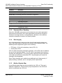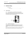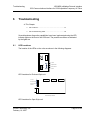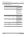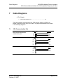
1
1550 MBS Modbus Protocol Interface 1550 Communications Interface for 1336 Adjustable Frequency AC Drive User Manual February 16, 2005 Please Read This Notice Successful application of this module requires a reasonable working knowledge of the Allen Bradley Modbus Protocol Interface 1550 Communications Interface for 1336 Adjustable Frequency AC Drive hardware and the application in which the combination is to be used. For this reason, it is important that those responsible for implementation satisfy themselves that the combination will meet the needs of the application without exposing personnel or equipment to unsafe or inappropriate working conditions. This manual is provided to assist the user. Every attempt has been made to assure that the information provided is accurate and a true reflection of the product's installation requirements. In order to assure a complete understanding of the operation of the product, the user should read all applicable Allen Bradley documentation on the operation of the Allen Bradley hardware. Under no conditions will ProSoft Technology, Inc. be responsible or liable for indirect or consequential damages resulting from the use or application of the product. Reproduction of the contents of this manual, in whole or in part, without written permission from ProSoft Technology, Inc. is prohibited. Information in this manual is subject to change without notice and does not represent a commitment on the part of ProSoft Technology, Inc. Improvements and/or changes in this manual or the product may be made at any time. These changes will be made periodically to correct technical inaccuracies or typographical errors. Important Notice: The 1550 card allows remote access to commands in the Allen Bradley drives and other SCANport compatible devices. The user is responsible for assuring that any applicable regulations concerning the remote operation of equipment are adhered to. Your Feedback Please We always want you to feel that you made the right decision to use our products. If you have suggestions, comments, compliments or complaints about the product, documentation or support, please write or call us. ProSoft Technology, Inc. 1675 Chester Avenue, Second Floor Bakersfield, CA 93301 (661) 716-5100 (661) 716-5101 (Fax) http://www.prosoft-technology.com Copyright © ProSoft Technology, Inc. 2000 - 2005. All Rights Reserved. 1550 MBS User Manual February 16, 2005 Contents 1550 MBS ♦ Modbus Protocol Interface 1550 Communications Interface for 1336 Adjustable Frequency AC Drive Contents PLEASE READ THIS NOTICE...........................................................................................................2 Your Feedback Please ..................................................................................................................2 1 QUICK START GUIDE ................................................................................................................5 1.1 2 PRODUCT SPECIFICATIONS....................................................................................................7 2.1 Read/Write.....................................................................................................................7 2.1.2 Read Only......................................................................................................................7 Modbus Communications ............................................................................................11 3.1.1 Command/Reply Cycle................................................................................................11 3.1.2 Command Types .........................................................................................................11 3.1.3 Command Error Checking...........................................................................................12 3.1.4 Data Integrity ...............................................................................................................12 3.1.5 Modbus Register Map .................................................................................................12 HARDWARE SETUP.................................................................................................................15 4.1 5 General Specifications ...................................................................................................8 SLAVE PORT FUNCTIONALITY..............................................................................................11 3.1 4 Modbus Slave Specifications ........................................................................................7 2.1.1 2.2 3 Step-by-Step ....................................................................................................................5 1550 Card Setup ............................................................................................................15 4.1.1 Connecting Power to the 1550 Card - Enclosed Style ................................................15 4.1.2 Dip Switch Configuration .............................................................................................15 CONFIGURING DRIVE PARAMETERS ...................................................................................19 5.1 Data Transfer .................................................................................................................19 5.1.1 Controlling Drive Frequency........................................................................................19 5.1.2 Setting up the Adaptor I/O - Data Out .........................................................................20 5.1.3 Setting up the Adaptor I/O - Data In ............................................................................20 ProSoft Technology, Inc. February 16, 2005 Page 3 of 45 1550 MBS ♦ Modbus Protocol Interface 1550 Communications Interface for 1336 Adjustable Frequency AC Drive 6 7 Contents TROUBLESHOOTING.............................................................................................................. 21 6.1 LED Locations .............................................................................................................. 21 6.2 LED Troubleshooting Table ........................................................................................ 22 CABLE DIAGRAMS ................................................................................................................. 23 7.1 1550 Communication Port ........................................................................................... 23 APPENDIX A MODBUS REGISTER MAP ...................................................................................... 25 APPENDIX B DEVICE SPECIFIC HINTS........................................................................................ 27 SMC Dialogue Plus ..................................................................................................................... 27 SMP 3 27 APPENDIX C: MOUNTING INSTRUCTIONS—OPEN AND ENCLOSED STYLE UNITS ............. 29 Mounting the Communications Module ................................................................................... 29 Enclosed Style Communications .............................................................................................. 31 APPENDIX D: CABLE REQUIREMENTS....................................................................................... 35 1305 Drive .................................................................................................................................... 35 1336 PLUS (7.5-500HP) and 1336 FORCE................................................................................. 36 SMP 3 36 APPENDIX E: SCANPORT DATALINK OPERATION ................................................................... 39 SUPPORT, SERVICE & WARRANTY............................................................................................. 41 Support, Service and Warranty ................................................................................................. 41 Module Service and Repair ........................................................................................................ 41 General Warranty Policy ............................................................................................................ 42 Limitation of Liability.................................................................................................................. 42 Hardware Product Warranty Details ......................................................................................... 43 INDEX............................................................................................................................................... 45 Page 4 of 45 ProSoft Technology, Inc. February 16, 2005 Quick Start Guide 1 1550 MBS ♦ Modbus Protocol Interface 1550 Communications Interface for 1336 Adjustable Frequency AC Drive Quick Start Guide In This Chapter ¾ Step-by-Step ............................................................................ 5 In this section we have assembled a simple step-by-step procedure for installing and making the 1550 unit operational. This discussion presumes that the application decisions such as RS-232 versus RS-485, SCALper cable length, etc. have been addressed prior to this point. 1.1 Step-by-Step The following steps will allow the 1550 to be setup in the shortest period of time (the following steps refer to the Allen Bradley drive implementation. Similar steps are followed when interfacing to other A-B Power Division products): 1 Set the dip switches. The 1550 dip switch positions are detailed in Section 3 2 Mount the 1550 either in the drive or on the DIN rail. If using an Open Style, plug the unit into the drive. If using the Enclosed Style, mount the unit with DIN rail. See Appendix C for mounting instructions. 3 Connect power to the 1550. If working with an Open Style unit, there are no power connection concerns. When working with the 120 VAC or the 24 VDC Enclosed Style units, please refer to Section 3 4 Setup the Drive hardware. Refer to the appropriate drive manual to connect control and power to the drive. This aspect of the drive installation is out of the scope of this manual. 5 Setup the Drive parameters. See Section 4 of the manual to setup the drive parameters 6 Install the SCANport cable between the drive and the 1550. When using the Enclosed Style, a cable connection between the 1550 and the drive must be made to connect the SCANports together. See Appendix D for instructions. 7 Connect the serial communication cable between the host system and the 1550. Section 6 details the cable connection diagrams for RS-232, RS-422 and RS-485 connections to the 1550 unit. ProSoft Technology, Inc. February 16, 2005 Page 5 of 45 1550 MBS ♦ Modbus Protocol Interface 1550 Communications Interface for 1336 Adjustable Frequency AC Drive Page 6 of 45 Quick Start Guide ProSoft Technology, Inc. February 16, 2005 Product Specifications 2 1550 MBS ♦ Modbus Protocol Interface 1550 Communications Interface for 1336 Adjustable Frequency AC Drive Product Specifications In This Chapter ¾ Modbus Slave Specifications ................................................... 7 ¾ General Specifications ............................................................. 8 The ProSoft Technology, Inc. 1550-MBS card is a hardware product designed to be a communications front end for Allen Bradley SCANport compatible products (1336 Plus/Force/Vector and 1305, SMC Dialogue Plus, SMP3, etc.). The product includes the following functionality: 2.1 Modbus Slave Specifications Protocol modes: RTU mode with CRC-16 error checking Supported Modbus Function codes: 3 Read Multiple Data Registers 4 Read Input Registers 5 Force Single Coil 6 Preset (Write) Single Data Register 8 Loopback Test (Test 0 only) 16 Preset Multiple Data Registers (1 word per write) Supports broadcast commands from host Pre-assigned Modbus memory map 2.1.1 Read/Write Command Control/Frequency Datalinks Out A to D Up to 575 drive parameter values 2.1.2 Read Only Status/Feedback Datalinks In A to D ProSoft Technology, Inc. February 16, 2005 Page 7 of 45 1550 MBS ♦ Modbus Protocol Interface Product Specifications 1550 Communications Interface for 1336 Adjustable Frequency AC Drive 2.2 General Specifications Configuration via dip switches Slave Address 1 to 63 Baud Rate 300 to 19200 baud Parity None, Odd and Even Physical Link RS-232, RS-422 or RS-485 Stop Bits 1 or 2 Comm Configuration Modbus RTU Slave Modbus ASCII 7 or 8 bit Slave (future) SCANport Messaging Datalink A Enable (Type 4 Enable) Datalink B Enable (Type 5 Enable) Datalink C Enable (Type 6 Enable) Datalink D Enable (Type 7 Enable) Supplied in two forms: Open Style - Power supplied by drive Enclosed - Power supplied externally (120 VAC) Communication Port Connectors Modbus - 9 Pin Female SCANport - Regular A-B SCANport connection Status LED SCANport Status (bi-color) Serial Port Status (bi-color) Tx/Tx Activity Status (amber) Current Consumption : 60 ma DC Input Voltage Open Supplied by drive Enclosed 85 to 264 VAC, 1 Phase 45 to 63 Hz Page 8 of 45 ProSoft Technology, Inc. February 16, 2005 Product Specifications 1550 MBS ♦ Modbus Protocol Interface 1550 Communications Interface for 1336 Adjustable Frequency AC Drive Operating Temp 0 to 50 °C Storage Temp ProSoft Technology, Inc. February 16, 2005 -40 to 85 °C Page 9 of 45 1550 MBS ♦ Modbus Protocol Interface Product Specifications 1550 Communications Interface for 1336 Adjustable Frequency AC Drive Page 10 of 45 ProSoft Technology, Inc. February 16, 2005 Slave Port Functionality 1550 MBS ♦ Modbus Protocol Interface 1550 Communications Interface for 1336 Adjustable Frequency AC Drive 3 Slave Port Functionality In This Chapter ¾ 3.1 Modbus Communications....................................................... 11 Modbus Communications The 1550-MBS Modbus Slave card runs the RTU version of the Modbus protocol. This capability allows the module to communicate data from a A-B VFD to a Modbus Master host, and vice-versa. The module supports both point-topoint implementations as well as multi-drop implementations. The following discusses the functional capabilities of the 1550-MBS card. 3.1.1 Command/Reply Cycle Successful communications between the card and a host will always consist of the following two transactions: Command: Message from master giving instruction to slave. Reply: Response to command. A slave station will respond to a master issued command in several ways. Data Message: If the command was executed by the slave, the response message will include the data requested, or an acknowledgment that the command was executed. Error Message: If the command could not be executed by the slave, for whatever reason, an error response message is transmitted to the master. The error response message consists of the original function code (or'd with 80hex) and an error code. No Reply: If the master does not detect a reply within its timeout period, the master should re-transmit the command, before a time out error is issued. If the Slave could not decode the message or an error occurred preventing the Slave from recognizing the message, no response will be issued. 3.1.2 Command Types The 1550-MBS can respond to three types of commands from the master; read data, write data, and a diagnostic command. These are described below: Read Data:The following types of data read commands are supported: ProSoft Technology, Inc. February 16, 2005 Page 11 of 45 1550 MBS ♦ Modbus Protocol Interface Slave Port Functionality 1550 Communications Interface for 1336 Adjustable Frequency AC Drive Command Description 3 Read Multiple Registers 4 Read Input Registers Write Data:The following data write command is supported: Command Description 5 Force Single Coil 6 Single Register Write 16 Write Multiple Registers Diagnostics: The diagnostic command is supported: Command Description 8 Loopback Test - Code 0 3.1.3 Command Error Checking When the 1550-MBS cannot execute a command, an error code is generated and returned to the master. Error codes generated at the slave will usually be indicative of an illegal function, an illegal address, bad data, or the inability to complete a transaction because of a network problem. 3.1.4 Data Integrity As in all good protocols, there must exist a level of data integrity checking to verify, with some degree of assurance, the quality of the transmitted data. The Modbus protocol supports two types of error checking: RTU Mode : 16 bit cyclic redundancy check (CRC-16) One bit parity check CRC-16: When the master generates a message, a 16 bit CRC value is added to the end of the transmitted packet. The CRC value is generated using a series of bit shifts and manipulations. The receiving station executes the same calculation on the data and verifies the transmitted CRC. Any discrepancy will cause the message to be disregarded. Parity: Parity checking can be added as an additional level of data security. If parity checking is selected, even or odd parity can be implemented. 3.1.5 Modbus Register Map A pre-defined register map has been provided for the 1550 unit. This map is detailed in Appendix A. The full memory map is dependent on the A-B device which is connected to the 1550 unit. Page 12 of 45 ProSoft Technology, Inc. February 16, 2005 Slave Port Functionality 1550 MBS ♦ Modbus Protocol Interface 1550 Communications Interface for 1336 Adjustable Frequency AC Drive On power-up, the 1550 unit polls the remote device and determines the number of parameters that exist. If the number is greater than 575 the parameter list will be limited to 575. ProSoft Technology, Inc. February 16, 2005 Page 13 of 45 1550 MBS ♦ Modbus Protocol Interface Slave Port Functionality 1550 Communications Interface for 1336 Adjustable Frequency AC Drive Page 14 of 45 ProSoft Technology, Inc. February 16, 2005 Hardware Setup 4 1550 MBS ♦ Modbus Protocol Interface 1550 Communications Interface for 1336 Adjustable Frequency AC Drive Hardware Setup In This Chapter ¾ 4.1 1550 Card Setup .................................................................... 15 1550 Card Setup 4.1.1 Connecting Power to the 1550 Card - Enclosed Style Connecting power to the Enclosed Style Communication Module (1552 model) requires a simple termination of the 120 VAC cable to the front of the module. The connection is shown in the following diagram: 4.1.2 115 VAC Hot L 115 VAC Neutral N Ground G Dip Switch Configuration Configuration of the 1550 is independent of whether the unit is an internally mounted (1551) card or an externally mounted unit (1552). In either case, configuration consists of setting up some dip switches. The dip switches are as follows: Please note that dip switch configuration is read by the 1550 during the power up process. Power must be cycled if dip switches are changed under power. ProSoft Technology, Inc. February 16, 2005 Page 15 of 45 1550 MBS ♦ Modbus Protocol Interface 1550 Communications Interface for 1336 Adjustable Frequency AC Drive Hardware Setup Switch SW 1 Switch SW 2 Page 16 of 45 ProSoft Technology, Inc. February 16, 2005 Hardware Setup 1550 MBS ♦ Modbus Protocol Interface 1550 Communications Interface for 1336 Adjustable Frequency AC Drive Switch SW 3 ProSoft Technology, Inc. February 16, 2005 Page 17 of 45 1550 MBS ♦ Modbus Protocol Interface 1550 Communications Interface for 1336 Adjustable Frequency AC Drive Page 18 of 45 Hardware Setup ProSoft Technology, Inc. February 16, 2005 Configuring Drive Parameters 1550 MBS ♦ Modbus Protocol Interface 1550 Communications Interface for 1336 Adjustable Frequency AC Drive 5 Configuring Drive Parameters In This Chapter ¾ Data Transfer ......................................................................... 19 When the drive is first received, several parameters must be setup by the user in order for data transfer and control to be properly implemented. 5.1 Data Transfer 1 The 1550 units read and write data using three methods: 2 Control/Status Read and Write by default (Type 2 command ) 3 Datalinks A to D selected by dip switch (Type 4,5,6,7 commands) 4 Client/Server Messaging by default (Up to 575 parameters) When full datalinks ( A to D) are enabled , a total of 10 words of data can be transferred each way. Two of these words are dedicated to specific functions, leaving eight words for User configuration. In order to accomplish the transfer, the A-B Device’s I/O ADAPTOR Data In and Data Out parameters must be configured. A discussion on the SCANport link communications is excerpted from the A-B documentation and included in Appendix D. Please note that not all A-B Scanport devices support Datalinks. In particular, the SMC Dialogue Plus does not. To operate with the SMC Dialogue Plus do not enable the Datalink Messaging. 5.1.1 Controlling Drive Frequency The primary configuration which must be performed is associated with enabling Frequency Control from the 1550. In order to enable Frequency control from the 1550, the drive parameter FREQUENCY SELECT 2 must be configured for the appropriate Adapter ID representing the 1550 module. This will normally be Adaptor #2, unless a SCANport expander is being used (in which case this Adaptor number will be based on the port the 1550 is plugged into. ProSoft Technology, Inc. February 16, 2005 Page 19 of 45 1550 MBS ♦ Modbus Protocol Interface Configuring Drive Parameters 1550 Communications Interface for 1336 Adjustable Frequency AC Drive 5.1.2 Setting up the Adaptor I/O - Data Out Selects the parameter values which will be made available to the 1550 for reading into the register map. The Parameter Table can be found in Appendix A which details the placement of the values in the 1550. Data Out Image Suggested Parameter Description A1 54 Output Current A2 1 Output Volts B1 23 Output Power B2 53 DC Bus Voltage D1 19 Maximum Frequency D2 4 Last Fault C1 C2 5.1.3 Setting up the Adaptor I/O - Data In Selects the parameters which will be made accessible for configuration/ writing from the 1550. As with the Data Out parameters, there are eight possible selections. These may be chosen as needed to meet the needs of the application. Page 20 of 45 ProSoft Technology, Inc. February 16, 2005 Troubleshooting 6 1550 MBS ♦ Modbus Protocol Interface 1550 Communications Interface for 1336 Adjustable Frequency AC Drive Troubleshooting In This Chapter ¾ LED Locations........................................................................ 21 ¾ LED Troubleshooting Table ................................................... 22 Several hardware diagnostics capabilities have been implemented using the LED indicator lights on the front of the 1550 card. The possible conditions as indicated by the lights are: 6.1 LED Locations The location of the LEDs on the units are shown in the following diagrams: RX Active SCANport Status L N Serial Port Status G TX Active LED Locations for Enclosed Style unit TX Active Serial Port Status SW3 SW2 SW1 SCANport Status RX Active Front View Open Version LED Locations for Open Style unit ProSoft Technology, Inc. February 16, 2005 Page 21 of 45 1550 MBS ♦ Modbus Protocol Interface 1550 Communications Interface for 1336 Adjustable Frequency AC Drive 6.2 Troubleshooting LED Troubleshooting Table The following table details the meaning of the LEDs in the 1550 unit. NAME Color Status Indication Serial Port Status Green Blinking The 1550 has successfully processed a command from the host and has generated a response. Red Steady or Blinking The 1550 unit has detected a serial communication error condition on the Serial port. This is normally due to a bad communication transmission from a host such as an invalid command or a request for an invalid point. This LED will also be steady if SW3-4 is enabled and there is no communication on the serial port. SCANport Status RX Active Green Steady SCANport connection if OK Green Blinking Check cable connections. Indicates that the 1550 unit is not able to link up with the drive’s SCANport. Make sure that the AB device supports Datalinks if the 1550 Datalinks are enabled. Red Steady The SCANport connection has faulted. Check configuration switch settings, SCANport cable connections, cycle power. Contact ProSoft factory support if problem persists. Amber Blinking The 1550 Serial Port has detected some activity on the receive pins. Blinking The 1550 is sending out a response to the host. or Green TX Active Amber or Green Page 22 of 45 ProSoft Technology, Inc. February 16, 2005 Cable Diagrams 7 1550 MBS ♦ Modbus Protocol Interface 1550 Communications Interface for 1336 Adjustable Frequency AC Drive Cable Diagrams In This Chapter ¾ 1550 Communication Port...................................................... 23 The communication connections to the 1550 card are made via a DB-9 pin female connection on the front of the card. The physical terminations are shown in the following diagrams. 7.1 1550 Communication Port RS-232 w/ No Hardware Handshaking Port Connection with another communication port RS-422 4-wire Connection RS-485 2-wire Connection ProSoft Technology, Inc. February 16, 2005 1550 DB-9 Pin Female PC or Device TxD 2 RxD RxD 3 TxD COM 5 GND 1550 DB-9 Pin Female RS-422 Device TxD+ 9 RxD+ TxD- 4 RxD- RxD+ 6 TxD+ RxD- 2 TxD- COM 5 COM (Optional) 1550 DB-9 Pin Female RS-485 Device TxRxD+ 9 TxRxD+ TxRxD- 4 TxRxD- COM 5 COM Shield 3 Page 23 of 45 1550 MBS ♦ Modbus Protocol Interface 1550 Communications Interface for 1336 Adjustable Frequency AC Drive Page 24 of 45 Cable Diagrams ProSoft Technology, Inc. February 16, 2005 Appendix A Modbus Register Map 1550 MBS ♦ Modbus Protocol Interface 1550 Communications Interface for 1336 Adjustable Frequency AC Drive Appendix A Modbus Register Map FC FC FC Type 5 4 3 Reg Bit Description R/W 1 to 16 30001 40001 0 Command Control Word R/W 30002 40002 1 Type 2 - Word 2 R/W 30003 40003 2 Adaptor I/O - Out A1 Type 4 Command R/W 30004 40004 3 Adaptor I/O - Out A2 Type 4 Command R/W 30005 40005 4 Adaptor I/O - Out B1 Type 5 Command R/W 30006 40006 5 Adaptor I/O - Out B2 Type 5 Command R/W 30007 40007 6 Adaptor I/O - Out C1 Type 6 Command R/W 30008 40008 7 Adaptor I/O - Out C2 Type 6 Command R/W 30009 40009 8 Adaptor I/O - Out D1 Type 7 Command R/W 30010 40010 9 Adaptor I/O - Out D2 Type 7 Command R 30011 40011 10 Status Word R 30012 40012 11 Type 2 - Word 2 R 30013 40013 12 Adaptor I/O - In A1 Type 4 Command R 30014 40014 13 Adaptor I/O - In A2 Type 4 Command R 30015 40015 14 Adaptor I/O - In B1 Type 5 Command R 30016 40016 15 Adaptor I/O - In B2 Type 5 Command R 30017 40017 16 Adaptor I/O - In C1 Type 6 Command R 30018 40018 17 Adaptor I/O - In C2 Type 6 Command R 30019 40019 18 Adaptor I/O - In D1 Type 7 Command R 30020 40020 19 Adaptor I/O - In D2 Type 7 Command R 30021 40021 20 ScanPort Comm Status Device Parameter List R/W 30022 40022 21 1 R/W 30023 40023 22 2 R/W 30024 40024 23 3 R/W 30025 40025 24 4 R/W 30026 40026 25 5 R/W - R/W FC 3 Modbus Address = Parameter Number + 40021 R/W R/W 30xxx 40xxx Up to Max Parameter in Device (Up to 575 max) All register values in the 1550-MBS are presented in unscaled units. Please refer to the drive User manual for any necessary scaling information ProSoft Technology, Inc. February 16, 2005 Page 25 of 45 1550 MBS ♦ Modbus Protocol Interface Appendix A Modbus Register Map 1550 Communications Interface for 1336 Adjustable Frequency AC Drive Page 26 of 45 ProSoft Technology, Inc. February 16, 2005 Appendix B Device Specific Hints 1550 MBS ♦ Modbus Protocol Interface 1550 Communications Interface for 1336 Adjustable Frequency AC Drive Appendix B Device Specific Hints SMC Dialogue Plus The SMC Dialogue Plus does not support Datalinks, therefore the configuration of SW3 should not include any of the Datalinks Enabled. If a Datalink is enabled, the SCANport Status LED will toggle, indicating an error in the SCANport communications. The version of SMC which we tested (Rev 1.05) had 88 parameters. Each parameter was accessible in the Modbus register listing shown in Appendix A. Note that if one of the 88 parameters is to be changed from a host that the host must enable the EEPROM Storage function by writing a 2 into the Parameter Management parameter (17 - Modbus address 40038 ). SMP 3 The SMP3 does not support Datalinks, therefore the configuration of SW3 should not include any of the Datalinks Enabled. If a Datalink is enabled, the SCANport Status LED will toggle, indicating an error in the SCANport communications. The 1550 is able to read all of the parameters out of the SMP3 unit. ProSoft Technology, Inc. February 16, 2005 Page 27 of 45 1550 MBS ♦ Modbus Protocol Interface Appendix B Device Specific Hints 1550 Communications Interface for 1336 Adjustable Frequency AC Drive Page 28 of 45 ProSoft Technology, Inc. February 16, 2005 Appendix C: Mounting Instructions 1550 MBS ♦ Modbus Protocol Interface 1550 Communications Interface for 1336 Adjustable Frequency AC Drive Appendix C: Mounting Instructions Open and Enclosed Style Units In This Chapter ¾ Mounting the Communications Module .................................. 29 ¾ Enclosed Style Communications............................................ 31 Mounting the Communications Module The Communications Module can be provided in three mounting configurations Open style board, factory installed in a drive (not available for all drives)] Open style board as a separate kit Enclosed style for panel mount or DIN rail mount This section provides mounting information for the Enclosed style and the Open style kit. ProSoft Technology, Inc. February 16, 2005 Page 29 of 45 1550 MBS ♦ Modbus Protocol Interface Appendix C: Mounting Instructions 1550 Communications Interface for 1336 Adjustable Frequency AC Drive Figure C-1 Open Style Communications Module Mounting Location (1336 PLUS 7.5-500HP) Page 30 of 45 ProSoft Technology, Inc. February 16, 2005 Appendix C: Mounting Instructions 1550 MBS ♦ Modbus Protocol Interface 1550 Communications Interface for 1336 Adjustable Frequency AC Drive Enclosed Style Communications Module Dimensions Figure C-2 Enclosed Style Communications Module Dimensions ProSoft Technology, Inc. February 16, 2005 Page 31 of 45 1550 MBS ♦ Modbus Protocol Interface Appendix C: Mounting Instructions 1550 Communications Interface for 1336 Adjustable Frequency AC Drive Page 32 of 45 ProSoft Technology, Inc. February 16, 2005 Appendix C: Mounting Instructions 1550 MBS ♦ Modbus Protocol Interface 1550 Communications Interface for 1336 Adjustable Frequency AC Drive Figure C-3 Enclosed Style Communications Module Mounting Location (1336 FORCE Drive with Standard Adapter Board) ProSoft Technology, Inc. February 16, 2005 Page 33 of 45 1550 MBS ♦ Modbus Protocol Interface Appendix C: Mounting Instructions 1550 Communications Interface for 1336 Adjustable Frequency AC Drive Page 34 of 45 ProSoft Technology, Inc. February 16, 2005 Appendix D: Cable Requirements 1550 MBS ♦ Modbus Protocol Interface 1550 Communications Interface for 1336 Adjustable Frequency AC Drive Appendix D: Cable Requirements In This Chapter ¾ 1305 Drive.............................................................................. 35 ¾ 1336 PLUS (7.5-500HP) and 1336 FORCE........................... 36 ¾ SMP 3 .................................................................................... 36 SCANport cables are available in either Male to Male or Male to Female configuration. Cables of up to 10 meters (33 feet) can be connected from the master to the SCANport device (A in Figure D-1). If a Port Expander is used as shown in Figure D-1, the overall cable length from master to port expander to SCANport device must not exceed 10 meters (B1 + C = max 10 meters). 1305 Drive An Allen Bradley SCANport link cable is used to make the connection between the Communications Module and the drive (Figure D-1). Figure D-1 SCANport Connection on Communications Module ProSoft Technology, Inc. February 16, 2005 Page 35 of 45 1550 MBS ♦ Modbus Protocol Interface Appendix D: Cable Requirements 1550 Communications Interface for 1336 Adjustable Frequency AC Drive Important: The length of cable used between any two devices must not exceed 10 meters (33 feet). For example: A + B1 +C < 10 meters A + B2 +C < 10 meters B1 + B2 < 10 meters 1336 PLUS (7.5-500HP) and 1336 FORCE Refer to the product manual for correction information. On larger horsepower 1336 PLUS and FORCE drives with an open Communications Module mounted in the drive, no separate SCANport cable connection is required. SMP 3 An Allen Bradley SCANport cable is used to make the connection between the Communications Module and an SMP3. Page 36 of 45 ProSoft Technology, Inc. February 16, 2005 Appendix D: Cable Requirements 1550 MBS ♦ Modbus Protocol Interface 1550 Communications Interface for 1336 Adjustable Frequency AC Drive Figure D-2 SCANport Connection on Communications Module ProSoft Technology, Inc. February 16, 2005 Page 37 of 45 1550 MBS ♦ Modbus Protocol Interface Appendix D: Cable Requirements 1550 Communications Interface for 1336 Adjustable Frequency AC Drive Page 38 of 45 ProSoft Technology, Inc. February 16, 2005 Appendix E: SCANport Datalink Operation 1550 MBS ♦ Modbus Protocol Interface 1550 Communications Interface for 1336 Adjustable Frequency AC Drive Appendix E: SCANport Datalink Operation A datalink is a type of pointer used by some SCANport devices to transfer information to the drive. Datalinks allow parameter values to be written when the Logic Command and Reference are sent to the drive. Datalinks also allow parameter values to be read whenever the Logic Status and Feedback are read. SCANport devices that support this function have a group of parameters for Datalink configuration. These parameters are identified as “Datalink In” and “Datalink Out” parameters. The Datalink functions are enabled by setting the correct switch to “Enable” on SW3 of the Communications Module and configuring the “Datalink In” and “Datalink Out” parameters in the SCANport device. Each Datalink consists of two 16-bit words of input and two 16-bit words of output. Each of the two input words can be configured to write to a different destination parameter inside the SCANport device by setting the two “Datalink In” parameters for that Datalink to the desired destination parameters. Similarly, each of the two output words is configured by setting the two “Datalink Out” parameters for that Datalink. Each Datalink switch on SW3 can enable or disable one Datalink. If a Datalink is enabled the value of the parameters set in the “Datalink Out” parameters will be transferred to the Communications Module and the data sent by the Communications Module for the Datalink will be transferred into the parameters set in the “Datalink In” parameters. If a Datalink is not enabled the data transferred to the SCANport device for that Datalink will be zero and any data sent by the SCANport device will be ignored by the Communications Module. If no “Datalink In” parameter is configured for an input word that word will be ignored. If no “Datalink Out” parameter is configured for an output word the output word will be undefined (usually set to zero). ProSoft Technology, Inc. February 16, 2005 Page 39 of 45 1550 MBS ♦ Modbus Protocol Interface Appendix E: SCANport Datalink Operation 1550 Communications Interface for 1336 Adjustable Frequency AC Drive Page 40 of 45 ProSoft Technology, Inc. February 16, 2005 Support, Service & Warranty 1550 MBS ♦ Modbus Protocol Interface 1550 Communications Interface for 1336 Adjustable Frequency AC Drive Support, Service & Warranty ProSoft Technology, Inc. survives on its ability to provide meaningful support to its customers. Should any questions or problems arise, please feel free to contact us at: Web Site: http://www.prosoft-technology.com/support Internet E-mail address: [email protected] (661) 716-5100 Phone (661) 716-5101 (Fax) Postal Mail ProSoft Technology, Inc. 1675 Chester Avenue, Second Floor Bakersfield, CA 93301 Before calling for support, please prepare yourself for the call. In order to provide the best and quickest support possible, we will most likely ask for the following information (you may wish to fax it to us prior to calling): Support, Service and Warranty 1 Product Serial and Version Number 2 1550 Configuration Information o Dip Switches o Communication cabling An after-hours answering system (on the Bakersfield number) allows pager access to one of our qualified technical and/or application support engineers at any time to answer the questions that are important to you. Module Service and Repair The 1550 MBS device is an electronic product, designed and manufactured to function under somewhat adverse conditions. As with any product, through age, misapplication, or any one of many possible problems the device may require repair. When purchased from ProSoft Technology, Inc., the device has a 1 year parts and labor warranty according to the limits specified in the warranty. Replacement and/or returns should be directed to the distributor from whom the product was purchased. If you need to return the device for repair, obtain an RMA (Returned Material Authorization) number from ProSoft Technology, Inc.. Please call the ProSoft Technology, Inc. February 16, 2005 Page 41 of 45 1550 MBS ♦ Modbus Protocol Interface Support, Service & Warranty 1550 Communications Interface for 1336 Adjustable Frequency AC Drive factory for this number, and print the number prominently on the outside of the shipping carton used to return the device. General Warranty Policy ProSoft Technology, Inc. (Hereinafter referred to as ProSoft) warrants that the Product shall conform to and perform in accordance with published technical specifications and the accompanying written materials, and shall be free of defects in materials and workmanship, for the period of time herein indicated, such warranty period commencing upon receipt of the Product. This warranty is limited to the repair and/or replacement, at ProSoft's election, of defective or non-conforming Product, and ProSoft shall not be responsible for the failure of the Product to perform specified functions, or any other nonconformance caused by or attributable to: (a) any misapplication or misuse of the Product; (b) failure of Customer to adhere to any of ProSoft's specifications or instructions; (c) neglect of, abuse of, or accident to, the Product; or (d) any associated or complementary equipment or software not furnished by ProSoft. Limited warranty service may be obtained by delivering the Product to ProSoft and providing proof of purchase or receipt date. Customer agrees to insure the Product or assume the risk of loss or damage in transit, to prepay shipping charges to ProSoft, and to use the original shipping container or equivalent. Contact ProSoft Customer Service for further information. Limitation of Liability EXCEPT AS EXPRESSLY PROVIDED HEREIN, PROSOFT MAKES NO WARRANT OF ANY KIND, EXPRESSED OR IMPLIED, WITH RESPECT TO ANY EQUIPMENT, PARTS OR SERVICES PROVIDED PURSUANT TO THIS AGREEMENT, INCLUDING BUT NOT LIMITED TO THE IMPLIED WARRANTIES OF MERCHANT ABILITY AND FITNESS FOR A PARTICULAR PURPOSE. NEITHER PROSOFT OR ITS DEALER SHALL BE LIABLE FOR ANY OTHER DAMAGES, INCLUDING BUT NOT LIMITED TO DIRECT, INDIRECT, INCIDENTAL, SPECIAL OR CONSEQUENTIAL DAMAGES, WHETHER IN AN ACTION IN CONTRACT OR TORT (INCLUDING NEGLIGENCE AND STRICT LIABILITY), SUCH AS, BUT NOT LIMITED TO, LOSS OF ANTICIPATED PROFITS OR BENEFITS RESULTING FROM, OR ARISING OUT OF, OR IN CONNECTION WITH THE USE OR FURNISHING OF EQUIPMENT, PARTS OR SERVICES HEREUNDER OR THE PERFORMANCE, USE OR INABILITY TO USE THE SAME, EVEN IF PROSOFT OR ITS DEALER'S TOTAL LIABILITY EXCEED THE PRICE PAID FOR THE PRODUCT. Where directed by State Law, some of the above exclusions or limitations may not be applicable in some states. This warranty provides specific legal rights; other rights that vary from state to state may also exist. This warranty shall not be Page 42 of 45 ProSoft Technology, Inc. February 16, 2005 Support, Service & Warranty 1550 MBS ♦ Modbus Protocol Interface 1550 Communications Interface for 1336 Adjustable Frequency AC Drive applicable to the extent that any provisions of this warranty are prohibited by any Federal, State or Municipal Law that cannot be preempted. Hardware Product Warranty Details Warranty Period: ProSoft warranties hardware Product for a period of 1 year. Warranty Procedure: Upon return of the hardware Product ProSoft will, at its option, repair or replace Product at no additional charge, freight prepaid, except as set forth below. Repair parts and replacement Product will be furnished on an exchange basis and will be either reconditioned or new. All replaced Product and parts become the property of ProSoft. If ProSoft determines that the Product is not under warranty, it will, at the Customer's option, repair the Product using current ProSoft standard rates for parts and labor, and return the Product freight collect. ProSoft Technology, Inc. February 16, 2005 Page 43 of 45 1550 MBS ♦ Modbus Protocol Interface Support, Service & Warranty 1550 Communications Interface for 1336 Adjustable Frequency AC Drive Page 44 of 45 ProSoft Technology, Inc. February 16, 2005 Index 1550 MBS ♦ Modbus Protocol Interface 1550 Communications Interface for 1336 Adjustable Frequency AC Drive L Index 1 1305 Drive • 35 1336 PLUS (7.5-500HP) and 1336 FORCE • 36 1550 Card Setup • 15 1550 Communication Port • 23 A Appendix A Modbus Register Map • 25 Appendix B Device Specific Hints • 27 Appendix C Mounting Instructions—Open and Enclosed Style Units • 29 Appendix D Cable Requirements • 35 Appendix E SCANport Datalink Operation • 39 C Cable Diagrams • 23 Command Error Checking • 12 Command Types • 11 Command/Reply Cycle • 11 Configuring Drive Parameters • 19 Connecting Power to the 1550 Card Enclosed Style • 15 Controlling Drive Frequency • 19 D Data Integrity • 12 Data Transfer • 19 Dip Switch Configuration • 15 E Enclosed Style Communications • 31 G LED Locations • 21 LED Troubleshooting Table • 22 Limitation of Liability • 42 M Modbus Communications • 11 Modbus Register Map • 12 Modbus Slave Specifications • 7 Module Service and Repair • 41 Mounting the Communications Module • 29 P Please Read This Notice • 2 Product Specifications • 7 Q Quick Start Guide • 5 R Read Only • 7 Read/Write • 7 S Setting up the Adaptor I/O - Data In • 20 Setting up the Adaptor I/O - Data Out • 20 Slave Port Functionality • 11 SMP 3 • 36 Step-by-Step • 5 Support, Service & Warranty • 41 Support, Service and Warranty • 41 Switch SW 1 • 16 Switch SW 2 • 16 Switch SW 3 • 17 T Troubleshooting • 21 Y Your Feedback Please • 2 General Specifications • 8 General Warranty Policy • 42 H Hardware Product Warranty Details • 43 Hardware Setup • 15 ProSoft Technology, Inc. February 16, 2005 Page 45 of 45