1
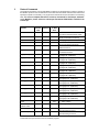
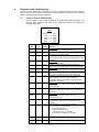
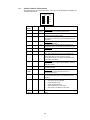
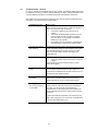
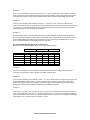
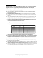
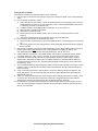
3100/3150 – LTQ
Limitorque Valve Actuator
Master Module
Revision 1.7
Allen-Bradley PLC 5
w/ ProSoft 3100-LTQ
(SLC support available
w / ProSoft 3150-LTQ)
Limitorque RS-232/485
Isolators/Converters
Loop Mode
Network of
Limitorque Valve
Actuators
Supports up to 150
valve actuators
Redundant
communications
Each device is an active
repeater on the network
Looped connections to the
LTQ module allows a single
line break or short
while maintaining
communications to all
actuators
USER MANUAL
February 2000
ProSoft Technology, Inc.
1675 Chester Ave., Fourth Floor
Bakersfield, CA 93301
[email protected]
Please Read This Notice
Successful application of the LTQ card requires a reasonable working
knowledge of the Allen-Bradley PLC or SLC hardware and the application in
which the combination is to be used. For this reason, it is important that those
responsible for implementing the LTQ satisfy them selves that the combination
will meet the needs of the application without exposing personnel or
equipment to unsafe or inappropriate working conditions.
This manual is provided to assist the user. Every attempt has been made to
assure that the information provided is accurate and a true reflection of the
product's installation requirements. In order to assure a complete
understanding of the operation of the product, the user should read all
applicable Allen-Bradley documentation on the operation of the A-B hardware.
Under no conditions will ProSoft Technology, Inc. be responsible or liable for
indirect or consequential damages resulting from the use or application of the
LTQ product.
Reproduction of the contents of this manual, in whole or in part, without written
permission from ProSoft Technology, Inc. is prohibited.
Information in this manual is subject to change without notice and does not
represent a commitment on the part of ProSoft Technology, Inc. Improvements
and/or changes in this manual or the product may be made at any time. These
changes will be made periodically to correct technical inaccuracies or
typographical errors.
Copyright 1996, 1997, 1998, 2000 ProSoft Technology Inc.
Product Revision History
09/23/96
Revision 1.0
Initial release of product
04/30/97
Corrected manual errors
01/31/00
Add Accutronix MX documentation
02/23/00
Added Special Polling documentation
i
Implementation Guide
Integration of the LTQ module into a PLC or SLC application is easier the first time if a series of steps are
followed. In order to assist the first time users of our products in getting the LTQ operational quickly, we
have come up with this step-by-step implementation guide.
a)
Obtain project application and operation requirements. Read and understand all relevant
specifications drawings, diagrams, checkout procedures, performance audits, etc.
b)
Read the 3100/3150-LTQ User Manual.
c)
Obtain and read appropriate Limitorque supporting documents for product being networked. These
documents may be obtained from your local Limitorque representative or downloaded from the
Limitorque website: http://www.limitorque.com
435-23009
130-43510
440-20014
435-20013
437-13001
130-11000
DDC-100 Direct-to-Host Programming Guide
Accutronix MX DDC-100 Field Unit Installation and Operation Manual
DDC-100 UEC Field Unit (Modbus) Installation and Operation Manual
DDC-100 I/O Module Installation and Operation Manual
DDC-100 UEC Field Unit (UEC-3-DDC) Wiring & Startup Guidelines
Accutronix MX Installation & Operation Manual
d)
Starting with one of the ladder logic programs provided on disk with the LTQ, complete the following
steps:
PLC 5
LTQ5
SLC 5/03
LTQ503
e)
Edit the ladder logic provided on disk as needed for the application
Verify rack and slot location in program
Modify ladder instruction addresses as needed
Reference Appendix for tips in the SLC platform
f)
Setup the Communication Configuration parameters (See Section 2)
Determine the configuration requirements
Baud Rate, Slave Count, and the Active Slave Map
g)
Identify the jumper requirements (See Appendix)
h)
Make up the communication cables (See Section 5)
i)
Place processor into the run mode
j)
Monitor the data table Error Status values (See Section 2)
ii
Table of Contents
Revision History
Implementation Guide
i
ii
1 Product Specifications................................................................................................................................................. 1
2 LTQ Theoretical Operation ......................................................................................................................................... 2
2.1 Block Transferring Data to the Module ............................................................................................................. 2
2.1.1 Communications Configuration [ BTW Block ID 255 ]........................................................................... 3
2.1.2 Command Blocks [ BTW Block ID Code 0 to 5 ]..................................................................................... 7
2.2 Transferring data from the module [ BTR Block ID 0 to 30 ].......................................................................10
2.2.1 The Read Data Block Structure................................................................................................................11
2.2.2 Moving the data from the module to the processor..............................................................................11
2.2.3 Slave Data Results.....................................................................................................................................12
2.2.4 Command Done Bits .................................................................................................................................16
2.2.5 Module Information Table .........................................................................................................................15
3 Protocol Commands .................................................................................................................................................16
4 Diagnostics and Troubleshooting ..........................................................................................................................17
4.1 3100 PLC Platform LED Indicators .................................................................................................................19
4.2 3150 SLC Platform LED Indicators .................................................................................................................20
4.3 Troubleshooting - General................................................................................................................................21
4.4 Communication Error Codes ...........................................................................................................................22
5 Cable Connection ......................................................................................................................................................21
Appendix
Support, Service and Warranty
Jumper Configurations
SLC Programming Considerations
Limitorque Network Polling Scheme
Programming Recommendations
Example Ladder Logic
PLC-5
SLC-5/03
1
Product Specifications
The 3100/3150-LTQ (“Limitorque Valve Master Module”) product family allows Allen-Bradley 1771 and 1746
I/O compatible processors to easily interface as a host with up to 150 Limitorque Valve actuators.
The LTQ product includes the following standard features:
General Specifications
• Support for up to 150 Limitorque valve actuators
Supports all models, including:
MX/DDC-100
UEC-3-DDC Modbus
DDC-100M I/O Module
DDC-100M Field Unit
Valvcon IVO (unit is multidrop only)
• Implements Limitorque’s Port A/B polling scheme using both ports on the LTQ module
• RS-232 or RS-485 communications (jumper selectable)
• Software configuration (From processor ladder logic)
Baud Rate: 1,200 to 38,400
Message Response Timeout
Number of active slaves: 1 to 150
Last State on Comm Fail
Network Polling Scheme
Looped
Port 1 Only
Port 2 Only
Active Slave Table: Bit mapped
• Supported commands:
Continuously Polled
Read registers 40008 – 40013, Optional: 40055 or 40006/40007
Commands
Open
Stop
Close
Initiate Network ESD
Terminate Network ESD
Engage Contactors 1 - 6
Disengage Contactors 1 - 6
Position Valve (0 - 100%)
• Data returned to the ladder data table includes the following per valve:
Valve Position (0 – 100%)
Status Register
Fault Register
Digital Outputs
Digital Input Registers 1 and 2
Comm Error Code
Comm Counter
Special Polled Registers
• Response time
The protocol drivers are written in Assembly and in a compiled higher level language. As such,
the interrupt capabilities of the hardware are fully utilized to minimize delays, and to optimize the
product's performance
Hardware Specifications
• Backplane Current Load:
3100
3150
•
•
•
Operating Temperature
Storage Temperature
Connections:
3100
3150
: 0.65 A
: 0.15 A at 5 V
0.04 A at 24 V
: 0 to 60 C (32 to 140 F)
: -40 to 85 C (-40 to 185 F)
: 2 - DB25 Female Connectors
: 2 - DB9 Male Connectors
1
2
LTQ Theoretical Operation
Data transfers between the processor and the ProSoft Technology module occur using the Block Transfer
commands, in the case of the PLC, and M0/M1 data transfer commands, in the case of the SLC. These
commands transfer up to 64 physical registers per transfer. The logical data length changes depending on
the data transfer function.
The following discussion details the data structures used to transfer the different types of data between the
ProSoft Technology module and the processor. The term 'Block Transfer' is used generically in the following
discussion to depict the transfer of data blocks between the processor and the ProSoft Technology module.
Although a true Block Transfer function does not exist in the SLC, we have implemented a pseudo-block
transfer command in order to assure data integrity at the block level. Examples of the PLC and SLC ladder
logic are included in Appendix A.
In order for the ProSoft Technology module to function, the PLC must be in the
RUN mode, or in the REM RUN mode. If in any other mode (Fault/PGM), the
block transfers between the PLC and the module will stop, and
communications will halt until block transfers resume.
2.1
Block Transferring Data to the Module
Data transfer to the module from the processor is executed through the Block Transfer Write
function. The different types of data which are transferred require slightly different data block
structures, but the basic data structure is:
Word
0
Name
BTW Block ID
1 to 63
Data
BTW
Block ID
Description
A block page identifier code. This code is used by the
ProSoft module to determine what to do with the data
block. Valid codes are:
BTW
Code
Description
0
Open/Stop/Close/ESD Commands
1
Engage/Disengage 1 - 3 Commands
2
Engage/Disengage 4 - 6 Commands
3-5
Valve Position Commands
255
Module Communication Configuration
The data to be written to the module. The structure of
the data is dependent on the Block ID code. The
following sections provide details on the different
structures.
PLC
Memory
0
Open/Stop/Close
etc. Cmds
1
Engage/Disengage
Contactors 1-3
2
Engage/Disengage
Contactors 4-6
3
Valve Position
Cmd (1-48)
4
Valve Position
Cmd (49-96)
5
Valve Position
Cmd (97-150)
255
Configuration
Data
2
BTW
Command
Word
0
1
2
3
4
:
:
:
63
BTW Block ID
Although the full physical 64 words of the data buffer may not be used,
the BTW and M0 lengths must be configured for 64 words otherwise
module operation will be unpredictable.
2.1.1
Communications Configuration [ BTW Block ID 255 ]
The ProSoft Technology firmware communication parameters must be
configured at least once when the card is first powered up, and any time
thereafter when the parameters must be changed.
On power up, the module enters into a logical loop waiting to receive
configuration data from the processor. While waiting, the module sets the
second word of the BTR buffer to 255, telling the processor that the module
must be configured before anything else will be done. The module will
continuously perform block transfers until the communications configuration
parameters block is received. Upon receipt, the module will begin execution of
the command list if present, or begin looking for the command list from the
processor.
Transferring the Communications Configuration Parameters
to the module will force a reset of the communication ports
The configuration data block structure which must be transferred from the
processor to the module is as follows:
BTW Block ID 255
Word
0
1-10
11-20
BTW
Buffer
0
Data
Word
Description
BTW Block ID = 255
Config parameters
Active Slave Table
Description
Block ID Header = 255
Configuration Parameters
1
N[ ]:0
Baud Rate
2
N[ ]:1
Response Timeout
3
N[ ]:2
Max Number of Slaves
4
N[ ]:3
Read Block Count
5
N[ ]:4
Block Transfer Delay Count
6
N[ ]:5
Last State on Comm Fail
7
N[ ]:6
Network Poll Scheme
8
N[ ]:7
Propagation Delay
9
N[ ]:8
RTS to TxD Delay
10
N[ ]:9
Polling (special)
Active Slave Table
11-20
N[ ]:10-19 Slaves 1 - 150
Configuration Memory map for Example Application
Baud Rate 0
Read
Block
Count
Slave
Count
Response
Timeout
1
2
3
BT Delay
Count
Last
State
4
5
6
Polling
Scheme
Propagation
Delay
Polling (Special)
RTS to TxD
7
8
9
N7:0
7
200
16
0
0
0
0
0
0
0
Configuration Parm
N7:10
1
1
0
0
0
0
0
0
0
0
Active Slave Table
3
Name
Description
Baud Rate
The baud rate at which the port is to operate. The available
configurations are as follows:
Value
Baud Rate
2
1200 Baud
3
2400 Baud
4
4800 Baud
5
9600 Baud *
6
19200 Baud
7
38400 Baud
* Limitorque Field Unit Factory Default Setting
Message Response Timeout
This register represents the message response timeout period in 1
msec increments. This is the time which a port configured as a
Master will wait before re-transmitting a command if no response
is received from the addressed slave. The value is set depending
on the expected slave response times.
A value of 200 msec should be the minimal setting. Values from
200 to 65535 (0xffff) are permitted.
Max Number of Slaves
This value is used by the module to optimize the number of data
blocks returned to the PLC data table as well as several of the
internal logic routines. The value entered here can range from 1
to 150, and should always meet or exceed the last slave in the
Active Slave Table.
Read Data Block Count
This value represents the number of 50 word data blocks which
are to be transferred from the LTQ Module to the processor. The
blocks returned from the module start at block 0 and increment
from there. The maximum block count is 80.
As an example, a value of 5 will return BTR Block ID data blocks
0, 1, 2, 3, and 4, or module registers 0 to 249.
If a value of 0 is entered the LTQ module uses the Number of
Slaves configuration value to determine the Read Block Count
value.
Block Transfer Delay Counter
This is an empirical value used by the module to balance the
amount of time the module spends block transferring and the
amount spent handling port communications. The value entered is
used as a loop counter in the module, where each time through
the loop the count is incremented. When the count equals the
Block Transfer Delay Counter a Block Transfer sequence is
initiated.
Example: In Master Mode applications with the module in a remote
rack, the frequency of command execution can be improved by
entering a value of 75-150. The value must be determined
empirically.
Last State on Comm Fail
This value determines the state of the Limitorque read register
values which are returned to the PLC upon the detection of a
communication failure state (ie., comm has failed on both Port A
and B).
Value
Description
0
Clear last data values (default)
1
Maintain last data values
4
Network Polling Scheme
Value
Description
0
Loop Mode (Port 1 and 2 alternating)
1
Port 1 polling only
2
Port 2 polling only
The Network Loop Mode emulates Limitorque’s polling scheme
which takes advantage of the actuator ability to repeat data
transmissions and to operate in a looped mode. In this mode, the
module will alternate communications between Port 1 and 2.
Command failures on one port will be retried on the other port.
Active Slave Table
These 10 words allow the user to configure the specific slaves
which are active on a network. The intent of this table is to allow
the user to selectively enable slave addresses and therefore not
have to be concerned about activating slave addresses
continuously.
Active Slave Table
Word 0
15
Bits
0
1000 0000 0000 0001
Slave Address #1 Enable
Slave Address #16 Enable
All values are entered into the table in a right to left order with bit
0 representing the lower address. The slave addresses are
mapped into the table as follows:
Word
Description
0
Slaves 1 to 16
1
Slaves 17 to 32
2
Slaves 33 to 48
3
Slaves 49 to 64
4
Slaves 65 to 80
5
Slaves 81 to 96
6
Slaves 97 to 112
7
Slaves 113 to 128
8
Slaves 129 to 144
9
Slaves 145 to 150
Propagation Delay
Provides a delay time between primary port polls to prevent
network collisions on port changeover. Values should be no
lower than the listed minimal settings. The value represents delay
time in milliseconds.
Value
Number of Slaves
0
1 to 20
10
21 to 40
15
41 to 60
20
61 to 80
25
81 to 100
30
101 to 120
35
121 to 140
40
141 to 150
Note: These values are reference only. Empirical data gathered
on site will enable proper adjustment of these values.
Slave #1 Channel A Fail bit (port 1) being true AND all other slave
communications not in fault will be an indication of improper
adjustment of this value.
5
RTS to TxD
Polling (Special)
This value represents the time in 1 msec increments for delay
between asserting RTS and the actual transmission of data.
Delay between the receipt of messages and transmit of new
message must be greater than 10 msec. When used, a value of
20 is typically inserted into this field.
Note: This value is reference only. Empirical data gathered on site
will enable proper adjustment of these values.
Enables polling of specific registers in addition to the standard
polling. A value other than zero will cause an additional poll
request to be sent to the slaves that are enabled. The results are
placed in registers 8 and 9 in the slave response data block.
Using this feature has a performance cost as the time available
for the standard polling is shared with the special polling.
Value
Description
0
Disabled
1
Register 55, TP_BEFORE_MID_T_HIGH
2
Registers 6/7, Analog Input 1 and 2
6
2.1.2
Command Blocks [ BTW Block ID Code 0 to 5 ]
An LTQ Master port establishes communications and performs various communications
functions based on data the user has placed in the Command Blocks. The Command
Blocks are 60 word data blocks containing bit mapped ‘Enable Bits’. The actual command
executed by the module is determined by the user setting the correct ‘Enable Bit’ to a 1.
All commands are one-shoted by the module (ie., the module must see a 1 to 0 transition
before the command can be re-enabled with a 0 to 1 transition). The user may use the
‘Cmd Done Bit’ (See Section 2.2.4) to clear the command or any other means appropriate.
This command data, entered into the processor Data Table, is transferred to the module's
memory using Block IDs 0 through 5, depending on the command to be executed.
Word
0
1 to 10
11 to 20
21 to 30
31 to 40
41 to 50
51 to 60
Description
BTW Block ID Code ( = 0 )
Open Commands - Slaves 1-150
Stop Commands - Slaves 1-150
Close Commands - Slaves 1-150
Initiate ESD - Slaves 1-150
Terminate ESD - Slaves 1-150
Spare (Future)
Word
0
1 to 10
11 to 20
21 to 30
31 to 40
41 to 50
51 to 60
Description
BTW Block ID Code ( = 1 )
Engage Contactor #1 - Slaves 1-150
Disengage Contactor #1 - Slaves 1-150
Engage Contactor #2 - Slaves 1-150
Disengage Contactor #2- Slaves 1-150
Engage Contactor #3 - Slaves 1-150
Disengage Contactor #3 - Slaves 1-150
Word
0
1 to 10
11 to 20
21 to 30
31 to 40
41 to 50
51 to 60
Description
BTW Block ID Code ( = 2 )
Engage Contactor #4 - Slaves 1-150
Disengage Contactor #4 - Slaves 1-150
Engage Contactor #5 - Slaves 1-150
Disengage Contactor #5- Slaves 1-150
Engage Contactor #6 - Slaves 1-150
Disengage Contactor #6 - Slaves 1-150
Word
0
1 to 3
6 to 53
Description
BTW Block ID Code ( = 3 )
Analog Write Enable - Slaves 1 to 48
Analog Values - Slaves 1 to 48
Word
0
1 to 3
6 to 53
Description
BTW Block ID Code ( = 4 )
Analog Write Enable - Slaves 49 to 96
Analog Values - Slaves 49 to 96
Word
0
1 to 4
6 to 59
Description
BTW Block ID Code ( = 5 )
Analog Write Enable - Slaves 97 to 150
Analog Values - Slaves 97 to 150
7
Command Blocks
Block ID 0
16 Slave Address 1
0000 0000 0000 0001
32-17
Slave 16-1
0
Bit mapped Commands
(Ex. Send Open Command to slave #1)
64-49
1
48-33
2
96-81
3
80-65
4
5
127-113
150-144
112-97
143-128
6
7
8
9
N10:0
1
0
0
0
0
0
0
0
0
0
Open Commands
N10:10
0
0
0
0
0
0
0
0
0
0
Stop Commands
N10:20
0
0
0
0
0
0
0
0
0
0
Close Commands
N10:30
0
0
0
0
0
0
0
0
0
0
Init Net ESD Commands
N10:40
0
0
0
0
0
0
0
0
0
0
Stop Net ESD Commands
N10:50
0
0
0
0
0
0
0
0
0
0
Spare
Block ID 1
N10:60
1
0
0
0
0
0
0
0
0
0
Engage Contactor #1
N10:70
0
0
0
0
0
0
0
0
0
0
Disengage Contactor #1
N10:80
0
0
0
0
0
0
0
0
0
0
Engage Contactor #2
N10:90
0
0
0
0
0
0
0
0
0
0
Disengage Contactor #2
N10:100
0
0
0
0
0
0
0
0
0
0
Enagage Contactor #3
N10:110
0
0
0
0
0
0
0
0
0
0
Disengage Contactor #3
Block ID 2
N10:120
1
0
0
0
0
0
0
0
0
0
Engage Contactor #4
N10:130
0
0
0
0
0
0
0
0
0
0
Disengage Contactor #4
N10:140
0
0
0
0
0
0
0
0
0
0
Engage Contactor #5
N10:150
0
0
0
0
0
0
0
0
0
0
Disengage Contactor #5
N10:160
0
0
0
0
0
0
0
0
0
0
Engage Contactor #6
N10:170
0
0
0
0
0
0
0
0
0
0
Disengage Contactor #6
8
Block ID 3
16 Slave Address 1 Bit mapped Commands
0000 0000 0000 0001 (Ex. Send Open Command to slave #1)
32-17
Slave 16-1
0
Valve Position Cmd Enables
1
48-33
2
3
4
5
6
7
8
9
N11:0
1
0
0
0
0
75
0
0
0
0
N11:10
0
0
0
0
0
0
0
0
0
0
N11:20
0
0
0
0
0
0
0
0
0
0
N11:30
0
0
0
0
0
0
0
0
0
0
N11:40
0
0
0
0
0
0
0
0
0
0
N11:50
0
0
0
0
0
0
0
0
0
0
Valve Position Values
( 0 to 100 %)
Block ID 4
80-65
Slave
64-49
0
Valve Position Cmd Enables
1
96-81
2
3
4
5
6
7
8
9
N11:60
1
0
0
0
0
30
0
0
0
0
N11:70
0
0
0
0
0
0
0
0
0
0
N11:80
0
0
0
0
0
0
0
0
0
0
N11:90
0
0
0
0
0
0
0
0
0
0
N11:100
0
0
0
0
0
0
0
0
0
0
N11:110
0
0
0
0
0
0
0
0
0
0
Valve Position Values
( 0 to 100 %)
Block ID 5
128-113
150-145 Valve Position Cmd Enables
Slave 112-97
144-129
0
1
2
3
4
5
6
7
8
9
N11:120
1
0
0
0
0
75
0
0
0
0
N11:130
0
0
0
0
0
0
0
0
0
0
N11:140
0
0
0
0
0
0
0
0
0
0
N11:150
0
0
0
0
0
0
0
0
0
0
N11:160
0
0
0
0
0
0
0
0
0
0
N11:170
0
0
0
0
0
0
0
0
0
0
9
Valve Position Values
( 0 to 100 %)
Command Usage for Limitorque Products
LTQ Commands
Open
Stop
Close
Start Network ESD
Stop Network ESD
Engage Relay #1
Engage Relay #2
Engage Relay #3
Engage Relay #4
Engage Relay #5
Engage Relay #6
Disengage Relay #1
Disengage Relay #2
Disengage Relay #3
Disengage Relay #4
Disengage Relay #5
Disengage Relay #6
2.2
MX-DDC
Yes
Yes
Yes
Yes
Yes
Yes (AS-1)
Yes (AS-2)
Yes (AS-3)
Yes (AS-4)
Yes (AR-1)
Yes (AR-2)
Yes (AS-1)
Yes (AS-2)
Yes (AS-3)
Yes (AS-4)
Yes (AR-1)
Yes (AR-2)
UEC-3-DDC
Yes
Yes
Yes
Yes
Yes
Do Not Use
Do Not Use
Yes (K3)
Do Not Use
Do Not Use
Yes (K6)
Do Not Use
Do Not Use
Yes (K3)
Do Not Use
Do Not Use
Yes (K6)
I/O Module
Do Not Use
Do Not Use
Do Not Use
Do Not Use
Do Not Use
Yes (K2)
Yes (K1)
Yes (K3)
Yes (K4)
Yes (K5)
Yes (K6)
Yes (K2)
Yes (K1)
Yes (K3)
Yes (K4)
Yes (K5)
Yes (K6)
Transferring data from the module [ BTR Block ID 0 to 30 ]
When the LTQ Master port driver reads data from a slave the resulting data is placed
into the ProSoft module’s data space (Addresses 0 to 1499). The structure of each set
of slave data is predetermined and programmed into the module (see below). The
position of each slave’s data structure is a function of the slave address, with the data
table beginning at slave 1 and working upwards.
The transfer of data from the ProSoft Technology module to the processor is executed
through the Block Transfer Read function. The following sections detail the handling of
the read data.
Although the full physical 64 words of the data buffer may not be
used, the BTR and M1 lengths must be configured for a length of 64
words, otherwise module operation will be unpredictable
The ladder logic must be programmed to look at the BTR buffer, decode several words,
and then take action.
10
2.2.1
The Read Data Block Structure
The BTR buffer definition is:
Word
0
Name
BTR Block ID
Description
The ladder logic uses this value to determine the
contents of the data portion of the BTR buffer. With
some conditional testing in ladder logic, the data from the
module can be placed into the PLC/SLC data table.
The relationship between the BTR Block ID number and
the register table can be put into an equation:
Starting Register Address = Block ID Number * 50
Valid codes are between 0 and 79.
1
BTW Block ID
The module returns this value to the processor to be
used to enable the movement of and command data
blocks to the module.
BTR Buffer
Word
0
1
2
3
4
:
:
:
63
2 to 51
(50
words)
52 to 61
(10
words)
2.2.2
Data
Command Done
Bits
BTR Block ID
BTW Block ID
BTW Buffer
Word
0
BTW Block ID
1
2
3
4
:
:
:
63
The contents of the module’s Register Data space (0 3999). The data will contain the slave data structure
for up to 5 slaves. The structure is outlined below.
These 10 words contain bit mapped Command Done
Bits which correspond to the slave address (i.e., bit 0
of the block corresponds to slave #1, etc.). These bits
are intended to be used to unlatch the Cmd Enable bits
through ladder logic.
Moving the data from the module to the processor
Data which has been read from the slave devices is deposited into a 4000
word register table in the module based on the slaves Modbus address.
The data register table is transferred from the module to the ladder logic
through a paging mechanism designed to overcome the 64 physical word limit
of the BTR instruction. The paging mechanism is outlined in the discussion
above, but the important thing to understand is the relationship between the
page numbers (BTR Block ID numbers) and the register addresses in the
module.
The diagram also shows the layout for an example application. Note the
number of blocks returned from the module to the ladder logic is d etermined by
the value entered in the module’s configuration ‘Max Number of Slaves’
register, or if non-zero, the value in ‘Read Block Count’. In this example we have
assumed a ‘Max Slave Count’ value of 15, allowing three (3) data blocks to be
returned from the module.
11
LTQ Module
Memory
PLC Data Memory
PLC
Data
Addr
N12:0
Read
Data
Block
Block ID 0 to 79
Address : 0 to 3999
Slave Structure #1
Slave Structure #2
Slave Structure #3
Slave Structure #4
Slave Structure #5
N12:50
0
49
50
N12:100
99
100
N12:150
149
150
N12:200
199
200
N12:250
249
250
Block ID 0
Block ID 1
Block ID 2
Read Data from Slaves to PLC
These data blocks being returned
to the PLC will contain the slave data
in pre-formatted structures. Each block
will contain 50 words, with each slave
consuming 10 words. Each block
returns data for 5 slaves.
Block ID 3
Block ID 4
Block ID 14
1499
Read Data Blocks being returned from the LTQ module to the PLC data table. The actual number of
data blocks returned from the module is determined by the value ‘Max Number of Slaves’ entered
during module configuration (1 block is returned per 5 slaves).
2.2.3
Slave Data Results
The data values returned from each of the active slaves are placed in the
module’s data table and then transferred over to the PLC data table for
handling by the ladder logic. Several important points to understand include:
1.
2.
3.
4.
The position of each slave’s data in the module is determined solely
by the Slave Address
The positioning of data in the module begins with Slave Address 1
and goes to Slave Address 150 (Max number supported by the LTQ
module)
Each slave address, whether activated in the Active Slave Table or not,
has space reserved in the module
Non-contiguous slaves in the Active Slave Table will result in holes in
the data table being returned from the module. Although not normally a
problem, caution should be exercised when selecting slave
addresses to minimize these holes (ie., reduce the number of Block
Transfers needed to read back the data).
The structure of the BTR buffer when reading data from the module is as
follows:
Word
0
1
2 to 11
12 to 21
22 to 31
32 to 41
42 to 51
Description
BTR Block ID Code
BTW Block ID
Slave #1 Response
Slave #2 Response
Slave #3 Response
Slave #4 Response
Slave #5 Response
12
Command Response Block
(Example Logic)
Fault
Status Register
Valve
Digital
Register
Position
Outputs
0
1
2
3
Digital
Polling
Digital
Inputs 1
Inputs 2
Comm (Special)
Comm Counter
Polling
Status
(Special)
4
5
6
7
8
9
N12:0
0
2
0
0
33
0
0
320
0
0 Slave #1 Response
N12:10
50
68
0
0
0
0
0
320
0
0
N12:20
100
1
0
0
9
0
0
320
0
0 Slave #3 Response
N12:30
0
3200
0
0
0
0
8
0
0
0 Slave #4 Response
N12:40
0
3200
0
0
0
0
8
0
0
0 Slave #5 Response
Slave #2 Response
Slave data after placement into the PLC data table.
Slave #x Response: The structure of each slaves read data and
communication status data is as follows:
Position
0
1
2
Name
MX-DDC
UEC-3-DDC
Analog Register
Status Register
Bit
00
01
02
03
04
05
06
07
08
09
10
11
12
13
14
15
Fault Register
Bit
00
01
02
03
04
05
06
07
08
09
10
11
12
13
14
15
Valve Position (0 – 100%)
Valve Position (0 – 100%)
Opened
Closed
Stopped
Opening
Closing
Valve Jammed
Local Mode Selected
Combined Fault *
Thermal Overload Fault
Future Use
Channel A Fault
Channel B Fault
Open Torque Switch Fault
Close Torque Switch Fault
Manual Operation
Phase Error
Opened
Closed
Stopped
Opening
Closing
Valve Jammed
Local Mode Selected
Combined Fault *
Thermal Overload Fault
Fail De-Energize
Channel A Fault
Channel B Fault
Open Torque Switch Fault
Close Torque Switch Fault
Manual Operation
Phase Error
Not Used
Not Used
Not Used
Not Used
Phases Missing
Phase Reversed
Not Used
Not Used
Not Used
Not Used
Network ESD is ON **
Local ESD is ON
Unit Reset since last poll
Local Stop Selected
Opening in Local
Closing in Local
Open Verify Fault
Close Verify Fault
Open De-Energize Fault
Close De-Energize Fault
Phases Missing
Phase Reversed
Manual Mid to Open
Manual Open to Mid
Manual Mid to Close
Manual Close to Mid
Network ESD is ON**
Local ESD is ON
Unit Reset since last poll
Wrong Rotation
Opening in Local
Closing in Local
* Combined Fault:
Bit 07 of Field Unit Status Register (Word 1) indicates a fault when both bits 10 AND
11, or bit 05, or 08, or 09, or 15 indicate a fault.
** Field unit Network ESD
Parameter must be configured to Open, Stop, or Close.
13
Position
3
4
5
6
Name
Digital Output
Bit
00
01
02
03
04
05
06
07
08
09
10 - 15
Digital Inputs 1
Bit
00
01
02
03
04
05
06
07
08
09
10
11
12
13
14
15
Digital Inputs 2
Bit
00
01
02
03
04
05
06
07
08
09
10
11
12
13
14
15
Communication
Status Code
7
Communication
Counter
8
Polling (Special)
0
1
2
Polling (Special)
0
1
2
9
MX-DDC
UEC-3-DDC
Close Contactor
Open Contactor
AS-1
AS-2
AS-3
AS-4
AR-1, Opt
AR-2, Opt
AR-3, Opt
Network Relay
Not Used
Close Contactor
Open Contactor
User (K3)
SW-93 LED
SW-93 LED
User (K6)
N/A
N/A
Bits 08 - 15
Field Unit Software
Version ID
Remote Mode Selected
Thermal Overload Fault
Open Torque Switch
Open Limit Switch
Close Torque Switch
Close Limit Switch
Not Used
Not Used
User 0, Terminal-21
User 1, Terminal-10
User 2, Terminal-9
User 3, Terminal-6
User 4, Terminal-7
User 5, Terminal-5
User 6, Opt, Terminal-23
User 7, Opt, Terminal-24
Remote Mode Selected
Thermal Overload Fault
Open Torque Switch
Open Limit Switch
Close Torque Switch
Close Limit Switch
Aux. Open Input
Aux. Close Input
User 0, TB2-1
User 1, TB2-2
User 2, TB2-3
User 3, TB2-4
User 4, TB2-5
User 5, TB2-6
User 6, I/O Module Only
User 7, I/O Module Only
Not Used
Analog In 1 Lost
Not Used
Analog In 2 Lost
Analog In 1 Lost
Analog In 3 Lost
Analog In 2 Lost
Analog In 4 Lost
Network A/B Lost
Network A/B Lost
Not Used
Reserved
DDC Bd. Present
Reserved
I/O Opt Board Present
Reserved
Not Used
Reserved
Not Used
Reserved
Not Used
Reserved
Not Used
Reserved
Phase Lost
Phase Lost
Phase Reverse
Phase Reverse
User 8, Opt, Terminal-25
User 8, I/O Module Only
Not Used
User 9, I/O Module Only
See Trouble Shooting Section.
Do not use this word to determine Slave communication
status. Word N[ ]:1 (Status) bits 10 and 11 are preferred.
This is a module diagnostic word only.
This is a rollover counter (0 to 32767) which increments
upon completion of every successful communication
transaction with a slave. This counter will increment on
poll (read) commands as well as write commands.
Unused
TP_BEFORE_MID_T_HIGH Register 55
Analog 1 Register 6
Unused
Unused
Analog 2 Register 7
14
For a more complete discussion on register values for Limitorque
actuators or I/O Modules, please reference Limitorque Document
#435-23009, available from Limitorque.
15
2.2.4
Command Done Bits
The LTQ Module returns ‘Command Done’ bits to the ladder logic. A single bit
is returned per slave address, allowing ladder logic to be used to clear the
Command Enable bits. The following important points should be noted about
the Command Done bits:
1.
2.
3.
There is only one bit returned per slave address, not one bit per
command per slave. The implication of this is that one Done bit
must be used to clear all possible Enable bits for one slave
address. Example logic is provided in the Appendix
demonstrating this
The Command Done bit is a positive indication that the module
executed the command. It is not an indication of the command’s
success. A Done bit is returned to the ladder logic whether the
command was completed without error or not. This allows all
commands to be unlatched the same way. To determ ine if there
is a communication problem with a slave, verify the Channel A/B
Comm Status bits in the slave Status field.
The Done bit data registers in the module are cleared and then
updated prior to each backplane transfer sequence. This is done
to assure that the ladder logic receives the quickest possible
acknowledgment of a commands execution.
The structure of the Command Done bits in the BTR buffer when reading data
from the module is as follows:
Word
52
53
54
55
56
57
58
59
60
61
Description
Cmd Done - Slaves 1 - 16
Cmd Done - Slaves 17 - 32
Cmd Done - Slaves 33 - 48
Cmd Done - Slaves 49 - 64
Cmd Done - Slaves 65 - 80
Cmd Done - Slaves 81 - 96
Cmd Done - Slaves 97 - 112
Cmd Done - Slaves 113 - 128
Cmd Done - Slaves 129 - 144
Cmd Done - Slaves 145 - 150
16
2.2.5
Module Information Table
The LTQ Module provides product data to the ladder logic during power up
through the BTR data buffer whenever the BTW Block ID is set to 255. This data
is useful for determining revision information and can b e useful should support
be necessary from the factory. This 10 word block of data is returned in the BTR
data fields.
Word
0
1
2-3
4-5
6-7
8-9
10-11
Description
BTR Block ID Code
BTW Block ID( =255 )
Product Name (ASCII)
Revision (ASCII)
Operating System Rev(ASCII)
Production Run Number (ASCII)
Spare
Product Name: These two words represent the product name of the module in
an ASCII representation. In the case of the LTQ product, the letters ‘ LTQ ‘
should be displayed when placing the programming software in the ASCII data
representation mode.
Revision: These two words represent the product revision level of the firmware
in an ASCII representation. An example of the data displayed would be ‘1.01’
when placing the programming softw are in the ASCII data representation
mode.
Operating System Revision: These two words represent the module’s internal
operating system revision level in an ASCII representation.
Production Run Number: This number represents the ‘batch’ number that your
particular chip belongs to in an ASCII representation.
Revision
Module Type
N7:30
Operating System
Batch Number
0
1
2
3
4
5
6
7
8
9
LT
Q
1.
00
09
0
0
0
0
0
17
Module Info
3
Protocol Commands
The ProSoft Technology LTQ module Master module is pre-programmed to support a subset of
the Modbus protocol. The commands are hard coded into the module and have been selected to
implement specific functionality. The programmed commands are documented in the following
table. For a more complete discussion on these commands for Limitorque actuators
or I/O Modules, please reference Limitorque Document #435-23009, available from
Limitorque.
Command
Function
Modbus
Function
Code
3
Register
Address
Open Command
6
40001
Stop Command
Close Command
6
6
40001
40001
Start Network ESD
6
40001
Stop Network ESD
6
40001
Engage Relay #1
6
40001
Engage Relay #2
6
40001
Engage Relay #3
6
40001
Engage Relay #4
6
40001
Engage Relay #5
6
40001
Engage Relay #6
6
40001
Disengage Relay #1
6
40001
Disengage Relay #2
6
40001
Disengage Relay #3
6
40001
Disengage Relay #4
6
40001
Disengage Relay #5
6
40001
Disengage Relay #6
6
40001
Send Valve Position
Value
Enable Valve
Position Value
Poll Slave Special 1
6
40002
6
40001
3
40055
1
Poll Slave Special 2
3
40006
2
Poll Slave
40008
Count
or Write
Value
6
Description
Command is executed automatically to
any slave in the Active Slave Table
256
Open Command (Interlocked with
Close Command in the slave)
512
Disengages Open or Close
768
Close Command (Interlocked with
Open Command in the slave)
1280
Initiates Network ESD function in the
addressed slave
1536
Terminates Network ESD function in
the addressed slave
2304
Engages Relay #2 (I/O Module)
Engages AS-1 (MX-DDC)
2560
Engages Relay #1 (I/O Module)
Engages AS-2 (MX-DDC)
2816
Engages Relay #3
Engages AS-3 (MX-DDC)
3072
Engages Relay #4 (I/O Module)
Engages AS-4 (MX-DDC)
3328
Engages Relay #5 (I/O Module)
Engages AR-1 (MX-DDC)
3584
Engages Relay #6
Engages AR-2 (MX-DDC)
4352
Disengages Relay #2 (I/O Module)
Disengages AS -1 (MX-DDC)
4608
Disengages Relay #1 (I/O Module)
Disengages AS -2 (MX-DDC)
4864
Disengages Relay #3
Disengages AS -3 (MX-DDC)
5120
Disengages Relay #4 (I/O Module)
Disengages AS -4 (MX-DDC)
5376
Disengages Relay #5 (I/O Module)
Disengages AR -1 (MX-DDC)
5632
Disengages Relay #6
Disengages AR -2 (MX-DDC)
Value from Position to move actuator
PLC
0 - 100% of Open
6656
Move-To (enable)
Commands sent upon issuance from PLC ladder program
18
Command is executed automatically if
Special Polling is set to 1
Command is executed automatically if
Special Polling is set to 2
4
Diagnostics and Troubleshooting
Several hardware diagnostics capabilities have been implemented using the LED indicator
lights on the front of the module. The following sections explain the meaning of the individual
LEDs for both the PLC and the SLC platforms.
4.1
3100 PLC Platform LED Indicators
The PLC platform LTQ product is based on the ProSoft CIM hardware platform. The
following table documents the LEDs on the 3100-LTQ hardware and explains the
operation of the LEDs.
ProSoft CIM
Card
ACTIVE
CFG
ERR1
TXD1
RXD1
ProSoft
CIM
ACT
Color
Green
Status
Blink
(Fast)
On
Off
FLT
Red
Off
On
CFG
Green
Off
Blink
On
BPLN
Red
Off
On
ERR1
ERR2
Amber
Off
Blink
On
Tx1
Tx2
Rx1
Rx2
¡¡
¡¡
¡¡
¡¡
¡¡
FLT
BPLN
ERR2
TXD2
RXD2
Indication
Normal state: The module is operating normally and
successfully Block Transferring with the PLC
The module is receiving power from the backplane, but
there may be some other problem
The module is attempting to Block Transfer with the PLC
and has failed. The PLC may be in the PGM mode or may
be faulted
Normal State: No system problems are detected during
background diagnostics
A system problem was detected during background
diagnostics. Please contact factory for technical support
Normal state: No configuration related activity is occurring
at this time
This light blinks every time a Module Configuration block
(ID = 255) is received from the processor ladder logic
The light is on continuously whenever a configuration
error is detected. The error could be in the Port
Configuration data or in the System Configuration data.
See Section 4 for details
Normal State: When this light is off and the ACT light is
blinking quickly, the module is actively Block Transferring
data with the PLC
Indicates that Block Transfers between the PLC and the
module have failed. (Not activated in the initial release of
the product)
Normal State: When the error LED is off and the related
port is actively transferring data, there are no
communication errors
Periodic communication errors are occurring during data
communications. See Section 4 to determine the error
condition
This LED will stay on under several conditions:
•
CTS input is not being satisfied
•
Port Configuration Error
•
System Configuration Error
•
Unsuccessful comm on LTQ slave
•
Recurring error condition on LTQ master
Green
Blink
The port is transmitting data.
Green
Blink
The port is receiving data
19
4.2
3150 SLC Platform LED Indicators
The following table documents the LEDs on the 3150-LTQ hardware and explains the
operation of the LEDs.
COMMUNICATIONS
LED
Name
ACT
ERR2
Blink
(Fast)
On
Normal state: The module is operating normally and
successfully Block Transferring with the SLC
The module is receiving power from the backplane, but
there may be some other problem
The module is attempting to Block Transfer with the SLC
and has failed. The SLC may be in the PGM mode or may
be faulted
Normal State: No system problems are detected during
background diagnostics
A system problem was detected during background
diagnostics. Please contact factory for technical support
Normal state: No configuration related activity is occurring
at this time
This light blinks every time a Module Configuration block
(ID = 255) is received from the processor ladder logic
The light is on continuously whenever a configuration
error is detected. The error could be in the Port
Configuration data or in the System Configuration data.
See Section 4 for details
Normal State: When this light is off and the ACT light is
blinking quickly, the module is actively Block Transferring
data with the SLC
Indicates that Block Transfers between the SLC and the
module have failed
Normal State: When the error LED is off and the related
port is actively transferring data, there are no
communication errors
Periodic communication errors are occurring during data
communications. See Section 4 to determine the error
condition
This LED will stay on under several conditions:
•
CTS input is not being satisfied
•
Port Configuration Error
•
System Configuration Error
•
Unsuccessful comm on LTQ slave
•
Recurring error condition on LTQ master
Red
Off
Green
Off
Red
Off
On
Amber
Off
Blink
On
PRT1
PRT2
ERR1
PRT2
Green
On
ERR1
ERR2
BPLN
PRT1
Indication
Blink
BPLN
CFG
Status
On
CFG
FAULT
Color
Off
FLT
ACT
Green
Blink
The port is communicating, either transmitting or receiving
data
20
4.3
Troubleshooting - General
In order to assist in the troubleshooting of the module, the following tables have been
put together to assist you. Please use the following to help in using the module, but if
you have additional questions or problems please do not hesitate to contact us.
The entries in this section have been placed in the order in which the problems would
most likely occur after powering up the module.
Problem Description
BPLN light is on (SLC)
Steps to take
The BPLN light comes on when the module does not think that
the SLC is in the run mode (ie., SLC is in PGM or is Faulted). If
the SLC is running then verify the following:
•
Verify the SLC Status File to be sure the slot is
enabled
•
The Transfer Enable/Done Bits (I/O Bits 0 for the slot
with the module) must be controlled by the ladder
logic. See Section 2.2.4 for details or the example
ladder logic in the Appendix.
•
If the ladder logic for the module is in a subroutine file
verify that there is a JSR command calling the SBR
CFG light does not clear
after power up
If the BPLN light has been cleared, then several of the Port and
System configuration values are value checked by the module
to be sure that legal entries have been entered in the data
table. Verify the Error Status Table for an indication of a
configuration error.
Module is not transmitting
Presuming that the processor is in run, verify the following:
•
Check Error Status codes for 255 code. If so see next
problem
If all the ladder logic is block transferring with the module
(Active LED is toggles)
Error Code 255 in Status
Table
This is caused by only one thing, a missing CTS input on the
port. If a cable is connected to the port, then verify that a
jumper has been installed between the RTS and CTS pins. If so
then there may be a hardware problem.
ERR light flashing
periodically
Intermittent communication error. Check slave error status
values and the Channel A/B Status bits for each slave to
determine where there may be a communication problem
New configuration values
are not being accepted
by the module
In order for new values to be moved to the module a Block
Transfer Write with a Block ID of 255 must be transmitted to
the module. The ‘User Config Bit’ in the example logic
accomplishes this. In the example logic the bit must either be
set in the data table manually or the module must be powered
down/reset.
In order to download the configuration upon transitioning from
PGM to RUN, simply add a run to set the ‘User Config Bit’ based
on the First Scan Status Bit (S1:1/15)
21
4.4
Communication Error Codes
The Error Codes returned from the module represent the outcome of the commands
and responses executed by the module. Note that in all cases, if a zero is returned,
there was not an error. Valid Error Status Codes are as follows:
Note:
These Error Codes are used for communication module diagnostics.
For programming purposes, use the Slave Data Table (Slave #x Response Data Word
N[ ]:1) for determining slave communication status.
Code
0
1
2
Name
All ok
Illegal Function
Bad Data Address
3
Bad Data Value
6
Module Busy
8
Timeout Error
10
Buffer Overflow
16
Port Configuration
Error
18
System Configuration
Error
254
Checksum Error
255
TX Hardware Timeout
22
Description
The module is operating as desired
An illegal function code request is being attempted
The address, or the range of addresses, covered
by a request from the master are not within
allowed limits
The value in the data field of the command is not
allowed.
The module busy status code is returned when a
write command from the master has not yet been
completed when a second write command is
received
Communications with the addressed slave have
been unsuccessful due to a lack of response from
the slave. The Master port will attempt a command
one time before alternating to the other
communications port.
The receive buffer has overflowed and reset the
character count to 0. If this condition occurs try
reading fewer parameters at one time
If this value is returned from the module, one or
both of the serial ports have been misconfigured.
To determine the exact source of the problem,
verify the following:
- Baud Rate Configuration
If this error is returned from the module, one of the
system configuration parameters has been
detected out of range. To determine the source,
verify the following:
- Read Block Count <= 80
- Write Block Count <=80
- Command Block Count <= 20
- Slave Error Pointer <= 3850
- Master Error Pointer <= 3880
The slave determined that the message checksum
was in error, and therefore discarded the
message
A transmit timeout condition has occurred
indicating that the module was not able to transmit
the command. Verify that the RTS-CTS jumper on
the port is still connected
5
Cable Connection
The following diagrams show the connection requirements for the ports on the 3100 and 3150
modules.
3100-LTQ Module
RS-485/2-Wire Connection
The jumper on the module
must be set in the RS-485
position
DO NOT USE 3100-LTQ pin 7
for connection of network cable
shield. Network cable shield
must be connected to proper
earth ground lug/ rod.
RS-232 to Limitorque Steered
RS-232/485 Converter
Limitorque PN 61-825-0966-4
Jumper must be added
between pins 4 and 5 on DB25 to DB-9 cable purchased
from Limitorque.
3100-LTQ
DB-25 Pin Female
Limitorque
Actuator
TxRxD+
14
Data +
TxRxD-
25
Data -
RTS
4
CTS
5
GND
7
RTS-CTS jumper must be installed for
card to communicate
3100-LTQ
DB-25 Pin Female
Limitorque
DB-9
TxD
2
3 - RxD
RxD
3
2 - TxD
RTS
4
CTS
5
GND
7
DTR
20
7 - RTS
RTS-CTS jumper must be installed for
card to communicate
5 - GND
3150-LTQ Module
RS-485/2-Wire Connection
The jumper on the module
must be set in the RS-485
position
DO NOT USE 3150-LTQ pin 5
for connection of network cable
shield. Network cable shield
must be connected to proper
earth ground lug/ rod.
RS-232 to Limitorque Steered
RS-232/485 Converter
Limitorque PN 61-825-0966-4
Cables purchased from
Limitorque as part of converter
assembly are DB-25 to DB-9.
The DB-25 will require 25-9 pin
adapter or replacement.
3150-LTQ
DB-9 Pin Male
Limitorque
Actuator
TxRxD+ 9
Data +
TxRxD-
1
Data -
RTS
7
CTS
8
GND
5
3150-LTQ
DB-9 Pin Male
RTS-CTS jumper must be installed for
card to communicate
Limitorque
DB-9
TxD
3
3 - RxD
RxD
2
2 - TxD
RTS
7
CTS
8
GND
5
DTR
4
23
7 - RTS
RTS-CTS jumper must be installed for
card to communicate
5 - GND
Typical Network Loop
with
Limitorque MX-DDC and UEC-3-DDC Actuators
3100/3150 - LTQ
RS-232
Port 1
Legend
- Motor Operated
- Data Positive
- Data Negative
- Data Positive
- Data Negative
- Data Positive
- Data Negative
- Data Positive
- Data Negative
- Shield
- No Connection
MOV
D-S
D-S*
D-M
D-M*
16
15
41
29
RS-232
Port 2
N/C
Limitorque
Limitorque
MOV-2
MOV-1
RS-232/485
TB3
D-M
D-M*
N/C
TB4
D-S
D-S*
41
29
16
15
30
N/C
TB5
Earth Ground
Earth Ground
Limitorque
Limitorque
MOV-150
RS-232/485
MOV-149
N/C
16
15
30
TB4
D-S
D-S*
41
29
N/C
TB3
D-M
D-M*
TB5
Earth Ground
Earth Ground
Notes:
1) Belden 3074F, 3105A, or 9841 shielded cable is recommended.
2) Correct polarity for field unit and 3100/3150-LTQ is required for
proper network operation.
3) Connections shown are typical. The number of MOVs shown
may not indicate true network size.
4)
Earth ground: ground rod.
5)
Earth ground: ground rod or lug in actuator if actuator
is grounded.
24
N/C
Support, Service and Warranty
Technical Support
ProSoft Technology survives on its ability to provide meaningful support to its
customers. Should any questions or problems arise, please feel free to contact us at:
Factory/Technical Support
ProSoft Technology, Inc.
9801 Camino Media, Suite 105
Bakersfield, CA 93311
(661) 664-7208
(800) 326-7066
(661) 664-7233 (fax)
E-mail address: [email protected]
Before calling for support, please prepare yourself for the call. In order to provide the
best and quickest support possible, we will m ost likely ask for the following information
(you may wish to fax it to us prior to calling):
1.
2.
3.
4.
5.
Product Version Number
Configuration Information
Communication Configuration
Jumper positions
System hierarchy
Physical connection information
Cable configuration
Module Operation
Block Transfers operation
LED patterns
An after-hours answering system (on the Bakersfield number) allows pager access to
one of our qualified technical and/or application support engineers at any time to
answer the questions that are important to you.
Module Service and Repair
The LTQ card is an electronic product, designed and manufactured to function under
somewhat adverse conditions. As with any product, through age, misapplication, or any
one of many possible problems, the card may require repair.
When purchased from ProSoft Technology, the module has a one year parts and labor
warranty according to the limits specified in the warranty. Replacement and/or returns
should be directed to the distributor from whom the product was purchased. If you need
to return the card for repair, it is first necessary to obtain an RMA number from ProSoft
Technology. Please call the factory for this number and display the number prominently
on the outside of the shipping carton used to return the card.
General Warranty Policy
ProSoft Technology, Inc. (Hereinafter referred to as ProSoft) warrants that the Product
shall conform to and perform in accordance with published technical specifications and
the accompanying written materials, and shall be free of defects in materials and
workmanship, for the period of time herein indicated, such warranty period commencing
upon receipt of the Product.
This warranty is limited to the repair and/or replacement, at ProSoft's election, of
defective or non-conforming Product, and ProSoft shall not be responsible for the failure
of the Product to perform specified functions, or any other non-conformance caused by
or attributable to: (a) any misapplication of misuse of the Product; (b) failure of Customer
to adhere to any of ProSoft's specifications or instructions; (c) neglect of, abuse of, or
accident to, the Product; or (d) any associated or complementary equipment or software
not furnished by ProSoft.
Support, Service and Warranty
Limited warranty service may be obtained by delivering the Product to ProSoft and
providing proof of purchase or receipt date. Customer agrees to insure the Product or
assume the risk of loss or damage in transit, to prepay shipping charges to ProSoft, and
to use the original shipping container or equivalent. Contact ProSoft Customer Service
for further information.
Limitation of Liability
EXCEPT AS EXPRESSLY PROVIDED HEREIN, PROSOFT MAKES NO WARRANT OF
ANY KIND, EXPRESSED OR IMPLIED, WITH RESPECT TO ANY EQUIPMENT, PARTS
OR SERVICES PROVIDED PURSUANT TO THIS AGREEMENT, INCLUDING BUT NOT
LIMITED TO THE IMPLIED WARRANTIES OF MERCHANT ABILITY AND FITNESS FOR A
PARTICULAR PURPOSE. NEITHER PROSOFT OR ITS DEALER SHALL BE LIABLE FOR
ANY OTHER DAMAGES, INCLUDING BUT NOT LIMITED TO DIRECT, INDIRECT,
INCIDENTAL, SPECIAL OR CONSEQUENTIAL DAMAGES, WHETHER IN AN ACTION IN
CONTRACT OR TORT (INCLUDING NEGLIGENCE AND STRICT LIABILITY), SUCH AS,
BUT NOT LIMITED TO, LOSS OF ANTICIPATED PROFITS OR BENEFITS RESULTING
FROM, OR ARISING OUT OF, OR IN CONNECTION WITH THE USE OR FURNISHING
OF EQUIPMENT, PARTS OR SERVICES HEREUNDER OR THE PERFORMANCE, USE
OR INABILITY TO USE THE SAME, EVEN IF PROSOFT OR ITS DEALER'S TOTAL
LIABILITY EXCEED THE PRICE PAID FOR THE PRODUCT.
Where directed by State Law, some of the above exclusions or limitations may not be
applicable in some states. This warranty provides specific legal rights; other rights that
vary from state to state may also exist. This warranty shall not be applicable to the extent
that any provisions of this warranty is prohibited by any Federal, State or Municipal Law
that cannot be preempted.
Hardware Product Warranty Details
Warranty Period : ProSoft warranties hardware product for a period of one (1) year.
Warranty Procedure : Upon return of the hardware Product ProSoft will, at its option,
repair or replace Product at no additional charge, freight prepaid, except as set forth
below. Repair parts and replacement Product will be furnished on an exchange basis
and will be either reconditioned or new. All replaced Product and parts become the
property of ProSoft. If ProSoft determines that the Product is not under warranty, it will, at
the Customer's option, repair the Product using current ProSoft standard rates for parts
and labor, and return the Product freight collect.
Support, Service and Warranty
Jumper Configurations
Hardware Overview
When purchasing the LTQ product, there are two available configurations. These choices are as
follows:
ProSoft Cat Number
PLC
SLC
3100
3150
Description
Module provided by ProSoft
When purchasing the module from ProSoft Technology, the jumper configurations will have been
factory set to default positions for testing prior to shipment.
Module Jumper Configurations
The following section details the available jumper configurations for the 1771 and 1746 platform
solutions. As needed, differences between the module based solutions and the firmware based
solutions are highlighted.
3100 for the 1771 Platform
Following are the jumper positions for the ProSoft Technology 3100-LTQ module:
Jumper
JW1
JW2
JW3
JW4
JW5
JW6
JW7
JW8
JW9
3100
N/A
N/A
N/A
Flash Pgm/Run Mode
8 Pt
Not Used
Enabled
Port 2 RS232/422/485 config
Port 1 RS232/422/485 config
JW4
Flash Pgm/Run Mode Select
Run Position
The position of this jumper should only be changed if needing to
reprogram the LTQ FLASH memory. This will only need to be done if
the module is to be upgraded in the field to a later version of firmware.
JW5
Backplane 8/16 point
8 Point
The module should be operated in the 8 point configuration unless
specifically directed otherwise by the factory.
JW7
Battery Enable / Disable
Enabled
This jumper should be placed in the Enabled position when the
module is powered up. Although not critical to the operation of the
module, this will back up some data registers in the module during a
power failure or reset.
JW8/9
RS Configuration for Port 1 and 2
RS-232
The default from factory is RS-232, but all options are supported by the
LTQ firmware
3150 for the 1746 Platform
Following are the jumper positions for the 3150-LTQ module:
Jumper
JW1
JW2
JW3
JW4
JW1/2
3150-LTQ
As Needed
As Needed
N/A
N/A
RS configuration for port 1 and 2
The default from factory is RS-232.
Jumper Configurations
RS-485 Position
Communication Port
Jumper Settings for 3150 Modules - JW1 & JW2
RS-232
RS-422
4-wire
RS-485
2-wire
RS-232
RS-422
4-wire
RS-485
2-wire
Jumper Configurations
SLC Programming Considerations
The 3150-LTQ is also very easy to get operational.
In order to implement the sample logic, the user must make sure that the correct processor and
rack size match up. Also, should it be necessary to re-locate the LTQ module, the user should be
certain to configure the correct slot as a 1746-BAS 5/02 Configuration.
When initially setting up the SLC program file, or when moving the module from one slot to
another, the user must configure the slot to accept the LTQ module.
It is important that the slot containing the ProSoft module be configured as
follows:
1746-BAS module or enter 13106 for the module code
Configure the M0/M1 files for 64 words
Configure I/O for 8 words
The following is a step by step on how to configure these files using Allen-Bradley APS
software. ICOM software users should follow similar steps.
From the Main Menu:
1) Select the correct processor program and F3 for Offline programming
2) F1 for Processor Functions
3) F1 for Change Processor
Modify the processor here if necessary (Note the LTQ will only work with 5/02 or
greater processors)
4) F5 for Configure I/O
Select 1746-BAS module for SLC 5/02 or greater, or enter 13106 for module code
5) F9 for SPIO Config when the correct slot is highlighted
6) F5 Advanced Setup
7) F5 for M0 file length - type in 64 and Enter
8) F6 for M1 file length - type in 64 and Enter
Esc out and save configuration
SLC Programming Considerations
Network Polling Scheme
In Looped Mode, the LTQ provides communication redundancy to each configured slave on the network.
The LTQ monitors the health of each communication path between port 1 and each configured slave and
between port 2 and each configured slave. LTQ port 1 communication status between port 1 and the
addressed slave is recorded in the slave Channel A s tatus bit. LTQ port 2 communication status between
port 2 and the addressed slave is recorded in the slave Channel B status bit. Both Channel A and
Channel B status bits are located in the slave Status register, bits 10 and 11(Word N[ ]:1/10 and 11).
On a healthy network where all configured slaves are communicating; the LTQ will first poll all slaves via
port 1, then poll all slaves via port 2, back to port 1, and so on. As each slave is successfully polled, the
respective Channel bit is set to 0 in the s lave Status register. Remember the LTQ port 1 equals Channel A
and the LTQ port 2 equals Channel B.
Should a slave not be reached on a poll, the LTQ will set the corresponding Channel Fail bit to 1, switch to
the other port and attempt to communicate with the same slave. Should the slave not communicate from
the second port, the corresponding Channel Fail bit will be set to 1, and the LTQ will resume polling on
the original port. Once the LTQ has completed polling all configured slaves on the first port, the polling
routine will switch to the other port and repeat the above process.
Example:
There are 5 slaves on the network and slave number 3 has been turned off. The LTQ is currently polling
the slaves through the LTQ port 1 (Channel A). Slave number 1 and 2 respond to the LTQ port 1 poll. Slave
number 3 does not respond to the port 1 poll causing the LTQ to set slave 3 Channel A bit to 1. The LTQ
now changes to port 2 (Channel B) and polls slave number 3. Slave number 3 does not respond to the
port 2 poll causing the LTQ to set the slave 3 Channel B bit to 1. Next the LTQ changes back to port 1 and
attempts to poll slave number 4. This communication attempt is successful and the LTQ now polls slave
number 5 through the LTQ port 1. Slave number 5 responds completing the port 1 poll.
Next the LTQ repeats the process through port 2 (Channel B). Slave 1 and 2 respond, slave 3 does not
respond and the LTQ sets the slave 3 Channel B bit to 1. The LTQ changes to port 1 (Channel A) and
attempts to communicate with slave 3. Slave 3 does not respond, the LTQ sets the slave 3 Channel A bit
to 1, switches back to port 2 and resumes polling the remainder of the configured slaves. Once slaves 4
and 5 have been successfully polled via port 2, the LTQ then switches to port 1 and repeats the polling
process. The port alternation process described above continues until slave 3 is powered on and the
communication fault clears.
Commands for slave control interrupt the polling process and are issued through the current poll port.
Once the slave has acknowledged the command, the LTQ resumes the polling process. In the event of a
communication fault between the current poll port and a commanded slave, the LTQ will issue the
command through the other communication port.
Looped Network Truth Table
(Recorded in Slave Status Register Bit 10 and 11)
Example 1
Example 2
Example 3
Example 4
Slave #
Ch. A
Ch. B
Ch. A
Ch. B
Ch. A
Ch. B
Ch. A
Ch. B
1
2
3
4
5
0
0
0
0
0
0
0
0
0
0
0
0
1
0
0
0
0
1
0
0
0
0
0
1
1
1
1
1
0
0
0
0
0
0
0
1
1
1
1
1
Example 1:
The LTQ is successfully communicating to each slave and sets the bits equating to Channel A and B to 0.
A value of 0 in the Channel A and B status indicate successful communication.
Limitorque Network Polling Scheme
Example 2:
The LTQ is successfully communicating to slaves 1, 2, 4, and 5 via both ports. Slave number 3 is without
power causing the slave 3 network board bypass relays to de-energize. This de-energizing of the bypass
relays shorts the signal through the network board and isolates the slave from the DDC-100 network.
Example 3:
The LTQ is successfully communicating to slaves 1, 2, 3 via port 1 and 4, 5 via port 2. When a slave
doesn’t communicate within a predetermined time-out period the LTQ sets the corresponding Channel bit
to a value of 1. This example indicates a wiring problem between slave 3 & 4. This problem is typically a
cable breakage, short, or improperly terminated wire.
Example 4:
The LTQ is attempting to communicate to the slaves via both ports but is unable to reach any slaves via
port 2. This typically indicates a broken cable connection at port 2 or at the first slave from port 2, broken or
shorted cable between the LTQ and the first slave from port 2, improperly terminated wires, or loss of
power to the RS-232/485 converter if attached to the LTQ port 2.
Non-Looped Network Truth Table via Port 1 Polling Only
(Recorded in Slave Status Register Bit 10, Bit 11 Channel B is always 0)
Example 5
Example 6
Example 7
Slave #
Ch. A
Ch. B
Ch. A
Ch. B
Ch. A
Ch. B
1
2
3
4
5
0
0
0
0
0
0
0
0
0
0
0
1
0
0
0
0
0
0
0
0
0
0
1
1
1
0
0
0
0
0
Example 5:
The LTQ is successfully communicating to each slave and sets the bits equating to Channel A to 0. A
value of 0 in the Channel A status indicates successful communication.
Example 6:
The LTQ is successfully communicating to slave 1, 3, 4, and 5. Slave 2 does not respond causing the LTQ
to set slave 2 Status register bit 10 to 1. In this example, slave 2 is without power causing the slave 2
network board bypass relays to de-energize. This de-energizing of the bypass relays shorts the signal
through the network board and isolates the slave from the DDC-100 network.
Example 7:
The LTQ is successfully communicating to slaves 1 and 2 but is not able to communicate to slaves 3, 4,
and 5 causing the LTQ to set slave 3, 4, 5 Status register bit 10 to 1. This typically indicates a broken or
shorted cable between slave 2 and 3, a broken cable connection at slave 2 or 3, improperly terminated
wires at slave 2 or 3, or loss of power to slaves 3, 4, and 5.
Limitorque Network Polling Scheme
Programming Recommendations
Programming the PLC to control a DDC-100 Network of Limitorque slaves will require information about
the design of the network. Limitorque recommends gathering this information before starting the
programming ta sk. After the programming has been completed, the network should be fully tested before
commissioning. The following recommendations are provided as the result of a number of successful
installations:
1) Obtain supporting Limitorque product documentation.
2) Obtain a wiring diagram of the digital inputs and digital outputs to the controlled devices (slaves)
before programming the PLC.
3) Develop a tag table for the installation. This table should include the tag name, network address,
desired status indication, com mand format.
4) If possible test the program prior to site installation. This will provide a program verification time for
debugging.
5) Attach a protocol analyzer to the DDC-100 network and monitor the timing, message structure, and
message issuance to verify the PLC code. This will assist in the diagnosis of proper command
issuing and sequencing of the host control algorithm.
6) Wire the DDC-100 Network per Limitorque’s network wiring recommendations. Ground loops, cable
termination’s, poor grounds, cable shields, and improper cables are frequently the cause of erratic
communication errors during the commissioning process.
Monitoring Slave Status
Network control involves two basic functions — monitoring slave status and issuing control commands.
The following checklist is provided for monitoring the status of the slaves:
Slave
Register
8
9
10
11
12
13
1)
2)
3)
4)
5)
6)
3100/3150-LTQ
Word
N[ ]:0
N[ ]:1
N[ ]:2
N[ ]:3
N[ ]:4
N[ ]:5
Definition
Valve Position
Status Register
Fault Register
Digital Outputs
Digital Inputs 1
Digital Inputs 2
Determine the LTQ time-out period. Verify that the time-out period is of sufficient duration to allow a
slave response under the worst-case conditions. Minimum time-out period is 200 msec.
Do not allow more than one LTQ control of the network at any time. A Hot Standby PLC with redundant
LTQ Modules requires careful programming considerations. Only one LTQ may be actively in control
at any time. Contact ProSoft for further details.
Slave register 10 bit 10 (Word N[ ]:2/10) will only report network ESD when the slave network ESD
parameter is set to any value but Ignore.
Slave register 9 bit 05 (Word N[ ]:1/5), Valve Jammed will only be active when the actuator is moving
the valve and the torque switch is tripped.
In MOV (Motor Operated Valve) mode, slave registers 9, 10, and 11 (Word N[ ]:1-3) bits are a value of 0
when false. A value of 1 indicates true. Registers 12 and 13 (Word N[ ]:4-5) bits typically are a value of
1 when true except register 12 bit 11 (Word N[ ]:4/11). See item 6 below.
In MOV mode, slave register 12 bit 11 (Word N[ ]:4/11), is default inverted to a value of 1 on false and 0
on true. The remaining bits in the high byte are default to a value of 0 on false and 1 on true.
Limitorque Programming Recommendations
Issuing Control Commands
The following checklist is provided for issuing control commands.
1) Use the proper command for the Limitorque slave to be commanded. Refer to the Command Usage
Table.
2) Prior to issuing commands to a slave:
a) Verify successful communication. This is accomplished via the normal polling proces s. Item 2.b
Combined Fault bit will be true if communications is lost to a slave (Status Register bits 10 and
11 (Word N[ ]:1/10 and 11) will also be true).
b) Combined Fault bit, Status Register bit 07 (Word N[ ]:1/7), is not a value of 1.
c) Verify the slave is capable of movement.
d) Verify slave is in Remote mode.
e) Slave (actuator) is not at desired position. (Do not send open command if slave is in open
position.)
f) Verify that the desired direction of travel does not have a torque switch fault.
3) Prior to issuing commands to an I/O Module style slave:
a) Verify successful communication. This is accomplished via the normal polling process. See Item
2.a.
b) When using 2 relays to control a single device, always disengage the first relay before engaging
the second relay.
4) After issuing a command, reset the command enable bit(s) to zero. Allow sufficient time for the block
transfer of the set bit(s) AND execution of the command(s) before resetting the bit(s) to zero.
Hint: Networked slave response times are approximately 50 - 120 ms. per slave.
5) A slave (actuator) configured for intermediate position control (Move-to) should be issued position
commands between 2 - 98% of open. Issue open or close commands for 0 and 100% of open.
6) Commands issued to the slave should never be repeated if the slave’s status register confirms
desired action. Repeated commands sent to the slave will result in increased network traffic and
increased network scan times. Also, repeating acknowledged commands may cause erratic slave
operation (e.g., stop).
7) The slave will automatically stop (disengage contactor) when the slave reaches the full open or close
position. There is no requirement for issuing a stop command when the slave reaches the open or
close limit switch.
8) A stop command may be used to stop the slave in mid-travel. When the slave has stopped in mid
travel (between the open and close limit switches) the slave Status Register bit 02 (Word N[ ]:1/2),
Stopped will be true (1).
9) There is no requirement to first issue a stop command when changing directions from open to close
or close to open. When the slave receives the command to change directions the slave will first
disengage the contactor (stop the actuator) then engage the opposing contactor.
10) A network stop command will stop the slave if the slave selector switch placed in Remote or Local
mode. The slave (actuator) local Stop pushbutton will stop the slave if the slave selector switch is in
Remote or Local mode.
Limitorque Programming Recommendations
Example PLC and SLC Ladder Logic
Overview
The following ladder logic provides an example for the ladder logic necessary to integrate the 3100-LTQ
and the 3150-LTQ modules into their respective processor platforms. This logic can be incorporated
directly as is, or if desired modified as needed for the application.
Data Files
The examples use the same memory map for both of the platforms, with the exception of the actual block
transfer data and control files.
The memory map for the example application has been detailed in the attached data table listing. Please
reference the right hand side of the data table listing for details.
Communication Configuration
Baud Rate
Slave
Response
Count
Timeout
Read
Block
Count
BT Delay
Count
Last
State
Polling
Scheme
Propagation
Delay
RTS to TxD
Polling
(Special)
0
1
2
3
4
5
6
7
8
9
N7:0
7
200
16
0
0
0
0
0
0
0
Configuration Parm
N7:10
1
1
0
0
0
0
0
0
0
0
Active Slave Table
16 Slave Address 1
0000 0000 0000 0001
32-17
Slave 16-1
0
Bit mapped Commands
(Ex. Send Open Command to slave #1)
64-49
1
48-33
2
96-81
3
80-65
4
5
127-113
150-144
112-97
143-128
6
7
8
9
N10:0
1
0
0
0
0
0
0
0
0
0
Open Commands
N10:10
0
0
0
0
0
0
0
0
0
0
Stop Commands
N10:20
0
0
0
0
0
0
0
0
0
0
Close Commands
N10:30
0
0
0
0
0
0
0
0
0
0
Init Net ESD Commands
N10:40
0
0
0
0
0
0
0
0
0
0
Stop Net ESD Commands
N10:50
0
0
0
0
0
0
0
0
0
0
Spare
Example Ladder Logic
N10:60
1
0
0
0
0
0
0
0
0
0
Engage Contactor #1
N10:70
0
0
0
0
0
0
0
0
0
0
Disengage Contactor #1
N10:80
0
0
0
0
0
0
0
0
0
0
Engage Contactor #2
N10:90
0
0
0
0
0
0
0
0
0
0
Disengage Contactor #2
N10:100
0
0
0
0
0
0
0
0
0
0
Enagage Contactor #3
N10:110
0
0
0
0
0
0
0
0
0
0
Disengage Contactor #3
N10:120
1
0
0
0
0
0
0
0
0
0
Engage Contactor #4
N10:130
0
0
0
0
0
0
0
0
0
0
Disengage Contactor #4
N10:140
0
0
0
0
0
0
0
0
0
0
Engage Contactor #5
N10:150
0
0
0
0
0
0
0
0
0
0
Disengage Contactor #5
N10:160
0
0
0
0
0
0
0
0
0
0
Engage Contactor #6
N10:170
0
0
0
0
0
0
0
0
0
0
Disengage Contactor #6
16 Slave Address 1 Bit mapped Commands
0000 0000 0000 0001 (Ex. Send Open Command to slave #1)
32-17
Slave 16-1
0
Valve Position Cmd Enables
1
48-33
2
3
4
5
6
7
8
9
N11:0
1
0
0
0
0
75
0
0
0
0
N11:10
0
0
0
0
0
0
0
0
0
0
N11:20
0
0
0
0
0
0
0
0
0
0
N11:30
0
0
0
0
0
0
0
0
0
0
N11:40
0
0
0
0
0
0
0
0
0
0
N11:50
0
0
0
0
0
0
0
0
0
0
Example Ladder Logic
Valve Position Values
( 0 to 100 %)
80-65
Slave 64-49
0
Valve Position Cmd Enables
1
96-81
2
3
4
5
6
7
8
9
N11:60
1
0
0
0
0
30
0
0
0
0
N11:70
0
0
0
0
0
0
0
0
0
0
N11:80
0
0
0
0
0
0
0
0
0
0
N11:90
0
0
0
0
0
0
0
0
0
0
N11:100
0
0
0
0
0
0
0
0
0
0
N11:110
0
0
0
0
0
0
0
0
0
0
128-113
150-145 Valve Position Cmd Enables
Slave 112-97
144-129
0
1
2
3
4
5
6
7
8
9
N11:120
1
0
0
0
0
75
0
0
0
0
N11:130
0
0
0
0
0
0
0
0
0
0
N11:140
0
0
0
0
0
0
0
0
0
0
N11:150
0
0
0
0
0
0
0
0
0
0
N11:160
0
0
0
0
0
0
0
0
0
0
N11:170
0
0
0
0
0
0
0
0
0
0
Example Ladder Logic
Valve Position Values
( 0 to 100 %)
Valve Position Values
( 0 to 100 %)