1
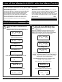
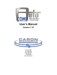
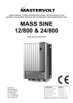
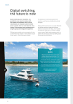
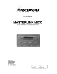
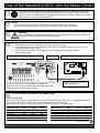
Use of the Masterlink MICC with the Mass Combi
This sheet describes the installation, initial settings and daily use of the Masterlink MICC remote
control panel in combination with the Mass Combi. Please review the entire manual of both the
Mass Combi and the Masterlink MICC for additional features and connections and to ensure best
performance and years of trouble-free service.
1
2
NOTES
• The Mass Combi can also be operated without any remote control panel connected;
• When using the Masterlink MICC panel, it is not possible to use the APC remote panel.
WARNING
During installation the Safety Guidelines & Measures are applicable at all times. See chapter 2 of
the manual of the Mass Combi and the Masterlink MICC.
3
4
INSTALLATION
1 Install the Mass Combi as described in the manual of the Mass Combi;
2 Install the Masterlink MICC as described in the manual of the Masterlink MICC, but do not connect
the modular communication cables;
3 Connect the Masterlink MICC to the Mass Combi as indicated below, using the modular
communication cable.
Connection compartment of the Mass Combi
1-2-3-4
INPUT
GEN / SHORE
50A MAX
L
N
PE
AC CONNECTIONS
OUTPUT
POWER
50A MAX
L
N
PE
OUTPUT
SHORT BREAK
25A MAX
L
N
PE
REMOTE
POS
QRS232 port
TEMP. SENS QRS232
BATTERY
Rear view of the Masterlink MICC panel
MASTERBUS
NEG
+5A
+
25A
SHORT BREAK
PUSH TO RESET
RJ12 modular communication
cable cross wired
NOTE: If two Mass Combi’s are installed in parallel, the
Masterlink MICC must be connected to the QRS232 port of the
Mass Combi that is configured as “Master”.
5
INITIAL DIP-SWITCH SETTINGS AT THE MASS COMBI
Power sharing level
The Power Sharing Level can be adjusted by means of the Masterlink MICC (see step 7). The absolute maximum
level for this setting can be fixed by means of DIP-switches B SW1, SW2 and SW3.
See sections 3.3.3 and 6.2.1 of the user’s manual of the Mass Combi for more information.
230V Models
DIP switch B
25 Amps.
16 Amps.
10 Amps.
6 Amps.
Disabled
SW1
OFF
ON
OFF
ON
---
SW2
OFF
OFF
ON
ON
---
SW3
OFF
OFF
OFF
OFF
ON
120V Models
DIP switch B
50 Amps.
30 Amps.
25 Amps.
15 Amps.
10 Amps.
SW1
--OFF
ON
OFF
ON
SW2
--OFF
OFF
ON
ON
SW3
ON
OFF
OFF
OFF
OFF
Please turn page
Mastervolt International B.V,
P.O.Box 22947, NL-1100 DK Amsterdam, The Netherlands.
Tel.: +31-20-3422100
Email: [email protected]
Web: www.mastervolt.com v1.2 071206EN
Use of the Masterlink MICC with the Mass Combi
INITIAL DIP-SWITCH SETTINGS AT THE MASS COMBI (CONTINUED)
Power Support Function
The Power Support Function can be enabled by means
of DIP-switch B-SW4. If enabled and the total demand
for AC power is more than the Power Sharing level,
load connected to the Short Break output will be
powered by the inverter while load connected to the
Power output will be powered by the external ACsource. See sections 3.3.5 and 6.2.2 of the user’s
manual of the Mass Combi for more information.
DIP switch B
Power support function disabled
Power support function enabled
6
Generator / mains support function
With the Generator / mains support function enabled,
AC power from the inverter is added to both AC outputs
if the total demand for AC power is higher than the
Power Sharing level. See section 3.3.4 and 6.2.3 of the
user’s manual of the Mass Combi for more information.
DIP switch B
Generator / mains support function disabled
Generator / mains support function enabled
SW4
OFF
ON
INITIAL SETTINGS AT THE MASTERLINK
MICC
Start from the initial menu to configure the
Masterlink MICC for use with the Mass Combi.
VOLT & CHG.AMP
25.54V
0.3A
7
DAILY USE OF THE MASTERLINK MICC:
Adjustment of the Power sharing / Power
support level
When the available current from the AC source is
limited (for instance to avoid the shore fuse from
tripping), the maximum AC input current of the Mass
Combi can be limited. Follow the steps below:
Hold Select pressed until the
Select LED starts blinking
VOLT & CHG.AMP
25.54V
0.3A
VOLT & CHG.AMP
25.54V
0.3A
Hold Select pressed until the
Select LED starts blinking
VOLT & CHG.AMP
25.54V
0.3A
Press Set-up once
SLEEP MODE
ON
Press Charger once
POWER SHARING.
25.0A
Ç
Press Select 3 times
HFC mode
OFF
Press Set-up once to enable the HFC mode
HFC mode
ON
Press Select once
Hold Select pressed for 5 sec. to change the arrow’s
direction. If pointing upwards (Ç), the Power sharing /
Power support level can be increased; if pointing
downwards (È), it can be lowered.
Press Set-up several times to adjust the Power
sharing / Power support level
After adjustment, press Select once
EXIT LEVEL
->PRESS SET-UP
EXIT LEVEL
->PRESS SET-UP
Press Set-up once.
Now the Select-LED stops blinking
Press Set-up once.
Now the Select-LED stops blinking
VOLT & CHG.AMP
25.54V
0.3A
VOLT & CHG.AMP
25.54V
0.3A
Ready!
Mastervolt International B.V,
SW5
OFF
ON
P.O.Box 22947, NL-1100 DK Amsterdam, The Netherlands.
Ready!
Tel.: +31-20-3422100
Email: [email protected]
Web: www.mastervolt.com v1.2 071206EN