1
User’s Manual
Version 1.10
P.O. Box 1529
1931 Sanford Rd.
Wells, ME 04090
p. 207.646.6071
f. 207.646.6983
www.caron-eng.com
AutoComp
Information in this document or the software it reflects is subject to change without notice and does
not represent a commitment on the part of Caron Engineering, Inc. No part of the manual or software
may be reproduced or transmitted in any form or by any means, electronic or mechanical, including
photocopying, recording, or information storage and retrieval systems, for any purpose other than the
purchaser's personal use, without the express written consent of Caron Engineering, Inc.
AutoComp is Trademark of Caron Engineering, Inc.
AutoComp™ software is copyrighted.
2012 Caron Engineering, Inc. All Rights Reserved
AutoComp™ is manufactured in the USA
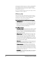
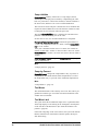
Table of Contents
AutoComp System Overview
Introduction
AutoComp Components
1
1
3
Overview of AutoComp Components
3
Gaging Devices
3
CNC Communication Interface
4
AutoComp PC Interface
4
AutoComp Functionality
5
AutoComp Functionality: Overview
5
How AutoComp Selects and Loads a Routine Automatically
6
Multi-Gage Routine Diagram
9
Demo Mode
PC Interface Components
10
11
PC Interface Components: Overview
11
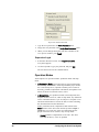
Main Window
11
Selection List Box
16
Keypad Screens
16
TestCNCOffsets Window
17
Initializing the AutoComp System
19
Initializing AutoComp: Introduction
19
Installing AutoComp
19
Activating AutoComp Licensing
20
CNC Interface Configuration: Overview
20
Gage Converter Configuration: Overview
33
Recap of Installation Process
40
Check System Global Parameters
40
Configuring the AutoComp System
41
Configuring the AutoComp System: Overview
41
User Options Window
41
System Configuration Window
47
i
Creating and Editing Routines
59
Creating and Editing Routines: Overview
59
Creating a Routine
59
Using the Edit Window
60
Adding a Dimension to an Existing Routine
65
Using the Detail Chart
68
Global Routine Parameters and Dimension Parameters
69
Global Routine Parameters and Dimension Parameters: Overview
69
Global Routine Parameters
69
Dimension Parameters
74
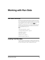
Working with Run Data
Run Data: Overview
85
Loading Test Run Data
85
Run Screen
87
Run Data Views
93
Run Data Log Files
Run Data File Format
ii
85
107
107
Glossary of Terms
109
Index
117
AutoComp System Overview
Introduction
Caron Engineering’s AutoComp system is an automatic tool compensation system that provides closed-loop machine control and
automatic tool wear feedback for your turning, grinding and milling
operations.
AutoComp calculates tool compensation based on tolerance and
compensation limits which you define for each measurement. The
system then sends tool compensation data directly to the CNC.
AutoComp measures tool wear by accumulating tool offsets over
successive machine cycles and provides a graphic indication of wear
to the operator in a user-friendly interface. You can choose any of
four graphic formats for viewing data and can toggle between them.
Tool Compensation Functionality
AutoComp automatically corrects for tool wear and other process
deviations by transmitting the measured deviation directly into the
CNC offset tables.
Flexible configuration for tool compensation. AutoComp collects data in real time from a gaging device, and can be configured
in either of two ways:
AutoComp System Overview
l
It can compensate each dimension directly, or
l
It can calculate a running average (also called a trend), which it
compares to user-programmed tool compensation limits. If the
average exceeds the limit, the CNC receives a compensation
value. The advantage in making compensation decisions based
on running averages instead of single part measurements is that
AutoComp can stabilize its response to variation. The running
average feature ignores small and unpredictable variations in the
process, compensating instead for large and consistent variations
such as tool wear.
1
Automatic or manual loading of data. The AutoComp system can
be configured to process gage data from automatic gaging loaded by
a robot, or to support manual gaging loaded by an operator.
Historical data. AutoComp maintains historical data for each cycle
of measurements. These data allow the operator to monitor tool
wear, and can be analyzed offline to adjust tool wear limits.
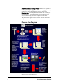
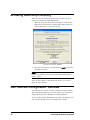
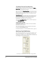
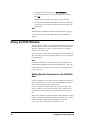
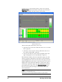
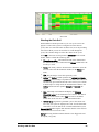
The process flow diagram outlines the basic function of the AutoComp system in a machine tool environment.
Process Flow Diagram
AutoComp Process Flow Diagram
2
AutoComp System Overview
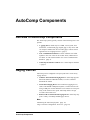
AutoComp Components
Overview of AutoComp Components
The AutoComp system typically consists of the following basic components.
l
A gaging device, which may be a CMM, vision system, laser
micrometer, LVDT-based gage, digital gage, or any device that
can output a standard text file. For other gages, contact CEI for
applications. See "Gaging Devices" (page 3).
l
CNC communication interface to allow automatic tool offset
updates to the CNC. This can be a Fanuc Focas, Okuma P control direct, or CEI custom interface. See "CNC Communication
Interface" (page 4).
l
AutoComp PC interface software. See "AutoComp PC Interface
" (page 4).
Gaging Devices
AutoComp can be configured to accept inputs from a wide variety
of gage devices.
l
CMM or other File-based Gaging Device. AutoComp supports
data from numerous CMM file formats, as well as a flexible
delimited file format.
l
LVDT-based Gaging Device. An LVDT-based gaging device,
such as a KurtUSB or Marposs EasyBox, is connected to the PC
using a USB port. LVDTs should be set to measure in close proximity to the electrical zero point. AutoComp allows for sign
reversal at the LVDT level.
l
RS232, USB or Wireless-based Gaging Device. AutoComp supports a variety of industry standard gage devices.
More:
"Initializing the AutoComp System" (page 19)
"Gage Converter Configuration: Overview" (page 33)
AutoComp Components
3
CNC Communication Interface
AutoComp supports several types of CNC interface for automatic
tool offset updates.
For more information and a listing of all the types of source
machine interface, see "Select the CNC Interface for the System"
(page 22), in "Initializing the AutoComp System" (page 19). If you
don’t see your machine type listed there, please contact Caron Engineering: we can create a custom CNC interface that meets your system’s needs.
More:
"Initializing the AutoComp System" (page 19)
"CNC Interface Configuration: Overview" (page 20)
AutoComp PC Interface
The AutoComp system requires Windows XP or Windows 7, running on a PC. For Okuma P control systems, AutoComp can be
installed directly on the control’s PC.
The user-friendly interface allows you to create, load, unload, and
delete part routines. It lets you view run time data in any of four
dynamic graphical presentations, and it lets you edit routines. In
addition, it provides you great flexibility in configuring AutoComp
to meet the needs of your machine environment.
More: "PC Interface Components" (page 11)
4
AutoComp Components
AutoComp Functionality
AutoComp Functionality: Overview
The basic building blocks used in AutoComp are routines and gage
data files. This chapter gives an overview of how routines and gage
data files are used in AutoComp, where only one gage is used to
measure all the dimensions in a routine (single-gage routine) and
where different dimensions in a routine may be measured by different gages (multi-gage routine).
Note that you can use AutoComp in demo mode, to acquaint yourself with the system's functionality. See "Demo Mode" (page 10) .
What Is a Routine?
A routine (or part routine) is a collection of dimensions and their
associated global routine parameters that is used by AutoComp in
the gage-compensation cycle. Each dimension in a routine contains the parameters for a specific measurement on a tooled part,
associated with a specific gage. As the dimension is tooled, the
gage puts out a gage data file.
All measurements marked as “critical” are required to complete a
cycle. When all critical dimensions are processed, the current cycle
is complete, even if other dimension measurements are missing.
Routines are automatically loaded and suspended by AutoComp as
gage data files are detected. When AutoComp automatically loads a
routine corresponding to a gage data file, it reads the routine file
and loads it into memory. (Note that only one routine can be loaded
at a time.)
As routines are suspended and later reloaded, all historical data are
preserved. To clear all historical data, manually unload the routine,
or use run data lifetime parameters.
What Is a Gage Data File?
A gage data file is created by the gage (or gage software application) that measures a dimension in a routine. This gage data file is
AutoComp Functionality
5
parsed by a gage converter program in AutoComp.
A routine may use only one gage or it may use many gages,
depending on your machine tooling needs and how your shop is
configured. AutoComp is able to handle information from many different gages in a given routine. Where more than one gage is used in a routine (in a “multi-gage routine”), the dimensions in a routine are not all measured by the same
gage. For example, most of the dimensions of a valve body might be
measured by a main CMM or Vision System gage, but one dimension might be measured by a different wireless gage.
For each dimension, the gage or gage software application puts
out a gage data file containing measurement values. AutoComp
detects the gage data files and loads the appropriate routine. The
gage data files are parsed by AutoComp definitions called gage converters. Every dimension that is specified in a routine must be associated with a gage converter.
Gage data file names are very important because AutoComp’s
ability to select and load the appropriate routine is contingent on
the data file name. You specify the gage data file name in a user
interface associated with each gage. Even though you name the
gage data files OUTSIDE OF AUTOCOMP, gage data file names
are explained in this chapter, because they are an important part of
how AutoComp works. See "How AutoComp Selects and Loads a
Routine Automatically" (page 6) and "Gage Data File Names"
(page 7), for more information.
How AutoComp Selects and Loads a Routine
Automatically
When a part is actually starting to be tooled, AutoComp selects and
loads the part routine automatically.
A routine is loaded automatically (and the currently-loaded routine
suspended) when AutoComp detects a gage data file in the configured gage folder. AutoComp selects and loads a routine that
matches the gage data file, using the following criteria:
l
6
Routine name. The routine name, or a portion of it, must be
included in the gage data file name. Up to the first 32 characters
of the gage data file are extracted to match a routine name.
o
If a routine exists whose name matches those characters
exactly, it is loaded.
o
If there is no exact match, AutoComp attempts to match a
routine from 31 characters down to 2. If a match is found,
that routine is loaded. If no match is found, an error message
is displayed on the screen.
AutoComp Functionality
l
Gage converter name. The gage converter is an AutoComp function that parses the gage data file. Unless all the routine dimensions use the default gage converter, the gage converter name
must be appended to the gage data file name in square brackets.
Routine Names
The routine name is important because it is used by AutoComp in
selecting and loading gage data files (whose names must include the
name of the routine they are associated with, or a portion of the
name). For the sake of user-friendliness, it is usually a good idea to
give the routine a descriptive name (such as “Valvebody”). (Note
that AutoComp is not case-sensitive.)
A routine is loaded automatically (and the currently loaded routine
suspended) when AutoComp detects a gage data file in the configured gage folder. AutoComp automatically selects and loads a
routine whose name matches the gage data file name. Note that it
does not have to be an exact match, but must contain the beginning
portion of the gage data file name.
Gage Data File Names
Each measurement is written to a gage data file, to be parsed by the
gage converter definition.
Note: You name the gage data files and set their file paths OUTSIDE OF AUTOCOMP; this process is NOT part of the AutoComp
system.
The gage data file name has three components:
l
All or part of the routine name with which it is associated and
optional additional characters
l
The gage converter name (in square brackets)
l
The file extension.
Routine name in the gage data file name. Gage data files are
always named to correspond to your routine name (whether or not it
is a multi-gage routine). Thus, if the routine name is “Valvebody,”
then “Valvebody” (or a portion of this routine name) must be part of
the gage data file name (for example “Valvebody1” or “ValveA”
could be part of the name).
Gage converter name. The gage data file name must include the
gage converter name in square brackets, unless all included routine
dimensions use the default gage converter. (If the default gage converter is used for all dimensions, you may include it in the file
name, but it is optional.)
File extension.The file extension is gage- or gage applicationdependent. Know your gage.
AutoComp Functionality
7
Thus, the format for a gage data file name is:
<Routine Name or portion of & optional char(s)><[gage converter name]>.<file ext>
For example:
l
A gage data file name where all the dimensions use the default
gage converter program could be “Valvebody1.txt,” or “ValveA.dat.”
l
In a multi-gage routine, or where a single gage that is not the
default is used, the gage data file name could be “Valvebody1[ZEISS].txt,” or “ValveA[MAHR].dat.”
Note: When you create a multi-gage routine, be sure to specify the
correct gage converter for each dimension.
CEI_CurrentRoutine Gage Files
If a gage data file matching a defined gage converter file filter and
path is seen and named:
CEI_CURRENTROUTINE[GageConverter].file_extension
where:
l
CEI_CURRENTROUTINE is the hardcoded filename,
l
GageConverter is the defined AutoComp gage converter, and
l
file_extension is the gage converter file filter extension,
then that file will be treated as if it is named for the currentlyloaded routine, and is merged into the current cycle. This can lessen
the times that file names need to be changed in gage applications.
Dimensions are still matched by gage converter name and data file
row number.
If no routine is loaded, an error message popup will note the routine
is empty and not loaded.
Note: AutoComp uses CEI_CURRENTROUTINE or CEIRTN to
send a gage data file to the currently loaded routine. A routine
should never be named either CEI_CURRENTROUTINE or
CEIRTN or the 'current routine' functionality will not work.
Instead, every time a gage data file of either of the above names is
detected, the routine of the matching name will be loaded.
8
AutoComp Functionality
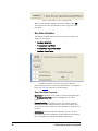
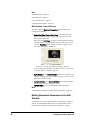
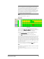
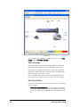
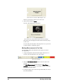
Multi-Gage Routine Diagram
The following illustration shows AutoComp functionality for a
multi-gage routine (where different dimensions in a routine are measured by different gages).
Multi-Gage Routine Diagram
AutoComp Functionality
9
Demo Mode
In demo mode, you use AutoComp's Test CNC interface. Caron
Engineering provides demo gage data files to allow you to test and
explore the AutoComp system.
More:
"AutoComp Functionality" (page 5)
"Loading Test Run Data" (page 85)
"Select the CNC Interface for the System" (page 22)
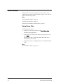
Using Demo Files
Load demo files as follows:
1. In the Test CNC Offsets window, press Send Gage Data.
The Demo Files folder opens.
2. In the Demo Files folder, select the desired gage data file and
press Open.
The data file is sent to AutoComp, and if the routine is not
already loaded, it is loaded.
3. Repeat this process to send gage data files for additional dimensions.
More:
"TestCNCOffsets Window" (page 17)
10
AutoComp Functionality
PC Interface Components
PC Interface Components: Overview
This chapter gives an overview of some basic PC interface components used by AutoComp. The following aspects of the PC interface are discussed here:
l
The "Main Window" (page 11) tool bar functionality
l
"Selection List Box" (page 16) that you use when loading routines or selecting gage converters or CNC interfaces, etc.
l
"Keypad Screens" (page 16) that you use to specify routine and
dimension names and add or edit numeric parameter information
l
"TestCNCOffsets Window" (page 17) that you use to load test
data (if you are using AutoComp’s Test CNC).
More:
"Initializing the AutoComp System" (page 19)
"Configuring the AutoComp System" (page 41)
"Creating and Editing Routines" (page 59)
"Working with Run Data" (page 85)
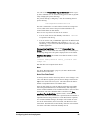
Main Window
AutoComp uses a familiar Windows-based graphical user interface.
The system supports either a touch-sensitive monitor or a standard
keyboard and mouse.
The Main Window’s components are:
PC Interface Components
l
Title bar, which displays the machine name.
l
Tool bar, which displays the functions available to supervisorlevel or operator-level users.
l
Run Screen area. The Run Screen area is only filled with a Run
Screen if a routine is loaded. It is discussed in detail in "Working with Run Data" (page 85).
11
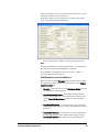
When AutoComp first starts (with no routine loaded), the Main Window appears as shown below (if the user is at supervisor level).
AutoComp Main Window with No Routine Loaded (Supervisor
Level)
If the user is at operator level, most of the Main Window functions
are not active and the tool bar appears as follows:
Main Window Tool Bar (Operator Level with No Routine Loaded)
The Main Window tool bar is always displayed, whether or not a
routine is loaded.
When a routine is loaded, the large area below the Main Window
tool bar (which is called the Run Screen) displays the run data. You
unload or suspend a routine using the Run Screen tool bar.
More:
"Working with Run Data" (page 85)
"Run Screen" (page 87)
Main Window Tool Bar Functions
The Main Window tool bar displays different functions depending
on whether it is set to supervisor or operator level. For more information, see "Security Levels" (page 43).
12
PC Interface Components
l
Supervisor level functions are: Edit, Load, Create, and Delete
routines, and About, Routine Path, Configuration, Help, and
View Log.
l
Operator level is restricted to: Load/Unload Routine, View Log,
About, and Help.
The Supervisor Level button that is displayed in the operator’s
tool bar opens the User Options window, where a supervisor can
log in.
All of the Main Window tool bar buttons are discussed below.
Edit Routines Button
This button opens a selection list box, where you can select an existing routine. Selecting a routine brings up the Edit window, where
you can add and change dimension parameters. The parameters
include general parameters, compensation parameters, and machine
parameters. You also enable tool compensation for a dimension from the Edit
window.
Note: To edit an active routine, use the Detail Chart.
More:
"Creating and Editing Routines" (page 59)
"Using the Detail Chart" (page 68)
Load Routine Button
This button opens a selection list box, where you can select an existing routine to load. This activates an existing compensation routine
for actual gage compensation.
When you load a routine, a Run Screen is displayed within the
Main Window and actual part measurement is enabled.
Routines are automatically loaded as gage data files are detected by
AutoComp.
Note: You can unload or suspend a routine by pressing the Unload
Routine or Suspend Routine button in the Run Screen.
More:
"Creating and Editing Routines" (page 59)
"Working with Run Data" (page 85)
"Using Demo Files" (page 10)
"Unload, and Suspend Routine Buttons" (page 92)
PC Interface Components
13
Create Routine Button
This button opens a keypad screen where you can specify the name
of the new routine.
After you enter the name, the Part Routines window opens, where
you can create a new tool compensation routine.
More:
"Creating and Editing Routines" (page 59)
Delete Routine Button
This button opens a selection list box where you can select the routine you want to delete. This removes the routine from the part routine directory.
More:
"Creating and Editing Routines" (page 59)
About Button
The About button opens a window that provides AutoComp version information and Caron Engineering contact information.
Routine Path Button
This button allows you to change the path where routine files are
kept. This may be desirable if you need to give the same name to
routines for different operations.
You can only do this if no routine is loaded.
Configuration Button
This button opens the User Options window, where you can set
user options including security level and run-data management
method.
The User Options window also lets you go to the System Configuration window, where you can set system configuration parameters including setup/production modes, system global
compensation rules and gage and CNC interface information.
More:
"Initializing the AutoComp System" (page 19)
"Configuring the AutoComp System" (page 41)
Help Button
The Help button lets you access AutoComp's online help. In the
online help, you can:
14
l
Find topics using the Table of Contents tab
l
Find topics using the Index tab
PC Interface Components
l
Find topics using the Search tab
l
Navigate from topic to topic using the Previous (page) and
Next (page button), and the Forward and Back buttons.
l
Locate current topic in the online help table of contents
l
Print topics using Print
l
Add "favorites" for quick access to specific topics. To do this, in
the Favorites tab, click on Add, at the bottom of the tab. The
topic is added to the list of favorites.
Note that you can resize the Help window or the panes of the window.
Note also that the AutoComp documentation is also available as a
.pdf document that you can print or view online.
View Log Button
This button displays the run time log file.
To view log file data, press the View Log button in the Main Window tool bar. The log file data are displayed in the AutoComp Information Log window.
AutoComp Information Log Window
More:
"Run Data Log Files" (page 107)
PC Interface Components
15
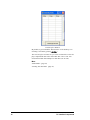
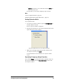
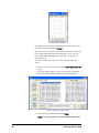
Selection List Box
When you edit, load, or delete an existing routine, you first press
the appropriate button in the Main Window tool bar.
A selection list dialog box appears, listing all the sources or routines in the part routines directory.
Selection List Box
Simply press the desired routine to select it, and then press OK.
More:
"Creating and Editing Routines" (page 59)
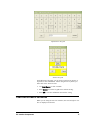
Keypad Screens
Keypad screens are data entry screens that let you specify routine
and dimension names and add or edit numeric parameter information. AutoComp uses two types of keypad screens—an alphanumeric keypad and a numeric keypad.
16
PC Interface Components
Alphanumeric Keypad
Numeric Keypad
For both kinds of keypads, you can use the touch screen, mouse, or
keyboard to enter information. When using the PC keyboard, you
must click in the white box first.
l
Use Back Space to clear a mistake.
l
Press Cancel to exit the keypad screen without saving.
l
Press OK to save the information and exit the screen.
TestCNCOffsets Window
When you are using the test CNC interface, the TestCNCOffsets window is displayed at all times:
PC Interface Components
17
TestCNCoffsets Window
(By default, it goes behind the Main Window on the desktop. You
can bring it forward by pressing Alt Tab.)
The TestCNCoffsets window lets you select test data files. It also displays compensated data in the offset table after a file is sent. You
can download data from multiple test data files (one at time).
More:
"Demo Mode" (page 10)
"Loading Test Run Data" (page 85)
18
PC Interface Components
Initializing the AutoComp
System
Initializing AutoComp: Introduction
There are several steps in preparing the system to receive gage data
and send CNC offsets. First you must initialize the system, as
described in this chapter. After you have initialized the system you
can set global parameters and create routines.
To initialize the system, you must complete the following steps, in
the order listed below.
l
Install AutoComp. See "Installing AutoComp" (page 19).
l
Activate AutoComp licensing. See "Activating AutoComp
Licensing" (page 20).
l
Configure the CNC interface by specifying the compensation
source machine. See "CNC Interface Configuration: Overview"
(page 20).
l
Configure gage converter(s) to process the gage data files for
your system (you may also configure a new gage converter if necessary). See "Gage Converter Configuration: Overview" (page
33).
After you have initialized the system, you must ensure that the system global parameters are set properly.
Installing AutoComp
Simply double click on the setup.exe file in the AutoComp folder to
begin the setup process.
Next you activate AutoComp licensing.
Initializing the AutoComp System
19
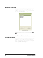
Activating AutoComp Licensing
Before you use AutoComp for the first time, you must activate it
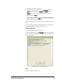
using a key provided by Caron Engineering. 1. When the Verify System License screen appears, contact Caron
Engineering (207-646-6071) with the MAC address shown on
your screen to receive your activation key.
Verify System License Window
2. Enter the activation key provided and press Apply to begin the
initialization process.
Note: If you only want to use the Test CNC interface, you do not
need an activation key. Just enter the AutoComp Demonstration
license: -98765.
After you have entered a valid AutoComp license, you can configure the CNC interface.
CNC Interface Configuration: Overview
In initializing your system, you must configure your CNC interface.
This entails specifying the type of CNC interface your system uses,
and specifying the CNC’s IP address and other parameters.
You access the window and dialog boxes where you configure your
CNC interface through the System Configuration window.
20
Initializing the AutoComp System
The System Configuration Window (CNC
Configuration)
The System Configuration window lets you access the windows and
dialog boxes where you select and configure the CNC interface.
To go to the System Configuration window:
1. In the Main Window toolbar, press Configuration to bring up
the User Options window.
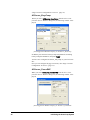
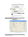
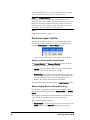
User Options Window
2. In the User Options window, set the access level to Supervisor
Level.
3. Press the System Configuration button.
The System Configuration window is displayed.
Initializing the AutoComp System
21
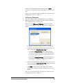
System Configuration Window
4. Press the CNC System button (near the upper left) to open a window where you can select the CNC interface for your system.
Select the CNC Interface for the System
AutoComp supports several types of CNC interface. Each type
requires different configuration parameters. (For more information,
see the interface types listed below.)
Note: If your machine type is not shown in the Select Compensation Source Machine window (see list below), please contact
Caron Engineering: we can create a custom CNC interface that
meets your system’s needs.
1. Select the CNC interface for the system as follows.
In the System Configuration window, press the CNC System
button to display the Select Compensation Source Machine
selection window, which lists all CNC interfaces supported by
AutoComp:
22
Initializing the AutoComp System
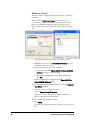
The Select Compensation Source Machine Selection Window
2. Highlight a device on the list and press OK. AutoComp will
send its offset data to this device.
Depending on the CNC type you selected, a window is displayed where you define the CNC’s unique characteristics. The
CNC types and the steps for configuring them are discussed in
the following sections. (Instructions for configuring each type
of interface are in the sections that follow, in the order listed in
the window shown above.)
After you have configured the CNC you can go on to configure
the gage converter(s).
More:
"ACSource_EasyComp" (page 24)
"ACSource_FanucDNC" (page 24)
"ACSource_FileSystem" (page 25)
"ACSource_Focas1" (page 26)
"ACSource_FTP" (page 27)
"ACSource_GetPutReadWrite" (page 27)
"ACSource_Haas" (page 28)
"ACSource_Heidenhain" (page 29)
"ACSource_OkumaLathe" (page 29)
"ACSource_OkumaMachining" (page 30)
"ACSource_OkumaRS232PP" (page 31)
"ACSource_TestCNC" (page 1)
Initializing the AutoComp System
23
"Gage Converter Configuration: Overview" (page 33)
ACSource_EasyComp
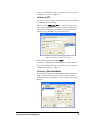
When you select ACSource_EasyComp from the Select Compensation Source Machine dialog box, the following window is displayed:
frmConfiguration Window Display for ACSource_EasyComp
Set RS232 port connected to EasyComp and parameters according
to EasyComp documentation, and press Apply.
You have now configured ACSource_EasyComp as your CNC interface.
Next you can configure the gage converter(s). See "Gage Converter
Configuration: Overview" (page 33).
ACSource_FanucDNC
When you select ACSource_FanucDNC from the Select Compensation Source Machine dialog box, the following window is displayed:
frmConfiguration Window Display for ACSource_FanucDNC
24
Initializing the AutoComp System
Enter all the required data for your machine, and press Apply.
You have now configured ACSource_FanucDNC as your CNC interface.
Next you can configure the gage converter(s). See "Gage Converter
Configuration: Overview" (page 33).
ACSource_FileSystem
This CNC interface produces formatted data files, by routine or by
dimension, for access by operators or by other applications. It does
not communicate directly with any CNC.
When you select ACSource_FileSystem from the Select Compensation Source Machine dialog box, the following window is displayed:
frmConfiguration Window Display for ACSource_FileSystem
1. Choose how you would like the files created, by selecting one
of the options in the Select Machine Type list:
o
If you choose File by Routine, AutoComp creates a file
with data for each dimension in the routine (one dimension
per line, in the order of the routine). The data file is named
<routine name>.csv.
o
If you choose File by Dimension, AutoComp creates a separate file for each dimension. Each data file is named <routine name>_<dimension name>.csv.
2. Specify the destination where CNC files are to be sent by clicking in the field under Enter CNC File Path, and then browsing
to the desired location and selecting it.
3. Press Apply to return to the System Configuration window.
You have now configured ACSource_FileSystem as your CNC
interface.
Next you can configure the gage converter(s). See "Gage Converter
Configuration: Overview" (page 33).
Initializing the AutoComp System
25
ACSource_Focas1
This CNC interface supports all Fanuc Focas versions, via Ethernet
or HSSB.
When you select ACSource_Focas1 from the Select Compensation Source Machine dialog box, two dialog boxes are displayed—a configuration dialog and a browse dialog, with the
browse dialog on top. You can move the browse dialog box to the
side.
frmConfiguration Window Display for ACSource_Focas1
1. Highlight your choice in the Select Machine Type list. (Currently there is only one choice.)
2. Specify the IP address of the CNC as follows:
a. Click in the field under Enter CNC IP or Node (if HSSB)
Address to display a numeric keypad.
b. Enter the IP or HSSB address using the keypad and then
press OK.
The IP or HSSB address is displayed in the Enter CNC IP or
Node (if HSSB) Address field.
3. If your control has both mill and lath axes, check the Complex
Tool Offset checkbox.
4. Select the Focas1 or 2 library as follows:
Click on Select Focas1/2 libraries.
A Browse for Folders dialog box is displayed that lets you
browse to and select the desired library.
4. Click on the desired library to select it.
5. Press Apply.
You have now configured ACSource_Focas1 as your CNC interface.
26
Initializing the AutoComp System
Next you can configure the gage converter(s). See "Gage Converter
Configuration: Overview" (page 33).
ACSource_FTP
If FTP is your choice, contact Caron Engineering. We can customize
your FTP data for your FTP site.
When you select ACSource_FTP from the Select Compensation
Source Machine dialog box, a window is displayed much like the
following. The fields where you can specify configuration information will vary depending on your system’s needs.
FTP Client Window for ACSource_FTP
Enter all the required data and press Apply.
You have now configured ACSource_FTP as your CNC interface.
Next you can configure the gage converter(s). See "Gage Converter
Configuration: Overview" (page 33).
ACSource_GetPutReadWrite
You can choose ACSource_GetPutReadWrite with Okuma RS232
(Lathe or Mill). This requires a CEI CNC program to initiate the
compensation, and a special RS232 cable. (Contact CEI for pinout
diagram.)
Initializing the AutoComp System
27
frmConfiguration Window Display for ACSource_GetPutReadWrite
The configuration process is the same as for the Okuma RS232
CNC, except that you must choose Lathe or Mill. See "ACSource_
OkumaRS232PP" (page 31).
Next you can configure the gage converter(s). See "Gage Converter
Configuration: Overview" (page 33).
ACSource_Haas
CEI provides the ACSource_Haas control on request. Note that if
you want to use this control, the CNC control setting 143 (parameter data) must be ON to enable Autocomp communication.
The following is from the Haas documentation.
Opening and navigating through Haas port setting pages:
l
“SETNG/GRAPH” button: Use this to enter the setting pages.
l
Page up/down buttons: Use to scroll through the setting pages.
l
Vertical cursor keys: Use to move to the desired setting. Alternatively, you can enter a setting number and press the down
arrow button to go directly to that setting.
Haas COM port settings:
28
l
11 Baud Rate SelectThis setting allows the operator to change
the rate at which data is transferred to/from the first serial port
(RS-232). This applies to the upload/download of programs etc.
and to DNC functions. This setting must match the transfer rate
from the personal computer.
l
12 Parity Select.This setting defines parity for the first serial
port (RS-232). When set to None, no parity bit is added to the
serial data. When set to zero, a 0 bit is added. Even and odd
work like normal parity functions. Make sure you know what
your system needs, for example, XMODEM must use 8 data bits
and no parity (set to “None”). This setting must match the transfer rate from the personal computer.
l
13 Stop Bit. This setting designates the number of stop bits for
the first serial port (RS-232). It can be 1 or 2. This setting must
match the transfer rate from the personal computer.
l
14 Synchronization. This changes the synchronization protocol between sender and receiver for the first serial port (RS232). This setting must match the transfer rate from the personal
computer. When set to RTS/CTS, the signal wires in the serial
data cable are used to tell the sender to temporarily stop sending
data while the receiver catches up.
l
XON/XOFF, the most common setting. When set to this setting,
the ASCII character codes are used by the receiver to tell the
sender to temporarily stop.
Initializing the AutoComp System
l
DC CODES is like XON/XOFF, except that paper tape punch
or reader start/stop codes are sent. XMODEM is a receiver-driven
communications protocol that sends data in blocks of 128 bytes.
XMODEM has added reliability as each block is checked for
integrity. XMODEM must use 8 data bits and no parity.
11 BAUD RATE SELECT: 38400 12 PARITY SELECT: NONE 13
STOP BIT: 1
14 SYNCHRONIZATION: XON/XOFF 37 RS-232 DATA BITS: 8
143 MACHINE DATA COLLECT: ON
ACSource_Heidenhain
When you select ACSource_Heidenhain from the Select Compensation Source Machine dialog box, the following window is displayed:
frmConfiguration Window Display for ACSource_Focas1
Enter the CNC IP of the system where the CEI CNC Server is running, and press Apply.
Contact Caron Engineering for more information on the CEI CNC
Server.
Next you can configure the gage converter(s). See "Gage Converter
Configuration: Overview" (page 33).
ACSource_OkumaLathe
The ACSource_OkumaLathe interface is for use with the Okuma
THINC API or an Okuma Lathe P200 control. When you select
ACSource_OkumaLathe from the Select Compensation Source
Machine dialog box, the following window is displayed:
Initializing the AutoComp System
29
frmConfiguration Window Display for ACSource_OkumaLathe
Since there is only one machine type available in the Select
Machine Type list, you do not need to select it
1. Specify the name or IP address of the CNC as follows:
a. Click in the field under Enter CNC IP Address to display a
keypad.
b. Enter the computer name or IP address using the keypad and
then press OK..
The computer name or IP address is displayed in the Enter
CNC IP Address field.
2. Press Apply.
You have now configured ACSource_FTP OkumaLathe as your
CNC interface.
Next you can configure the gage converter(s). See "Gage Converter
Configuration: Overview" (page 33).
ACSource_OkumaMachining
If your system is an Okuma Mill P200 control with Okuma THINC
API, you can use the ACSource_OkumaMachininginterface.
When you select ACSource_OkumaMachining from the Select
Compensation Source Machine dialog box, the following window
is displayed:
30
Initializing the AutoComp System
frmConfiguration Window Display for ACSource_OkumaMachining
Since there is only one machine type available in the Select
Machine Type list, you do not need to select it.
1. Specify the name or IP address of the CNC as follows:
a. Click in the field under Enter CNC IP Address to display a
keypad.
b. Enter the computer name or IP address using the keypad and
then press OK..
The computer name or IP address is displayed in the Enter
CNC IP Address field.
2. Press Apply.
You have now configured ACSource_FTP OkumaMachining as
your CNC interface.
Next you can configure the gage converter(s). See "Gage Converter
Configuration: Overview" (page 33).
ACSource_OkumaRS232PP
This CNC interface is for any Okuma non-P200 machine that has
the post processing option enabled.
When you select ACSource_OkumaRS232PP from the Select
Compensation Source Machine dialog box, the following window
is displayed:
Initializing the AutoComp System
31
frmConfiguration Window Display for ACSource_OkumaRS232PP
Enter all the required data for your machine, and press Apply.
You have now configured ACSource_OkumaRS232PP as your CNC
interface.
Note: You can also use the ACSource_GetPutReadWrite CNC interface for your Okuma RS232 machine. See "ACSource_GetPutReadWrite" (page 27).
Next you can configure the gage converter(s). See "Gage Converter
Configuration: Overview" (page 33).
ACSource_TestCNC
The Test CNC option lets you explore the AutoComp system in
demo or licensed mode. Just select ACSource_TestCNC from the Select Compensation
Source Machine dialog box. No further configuration is necessary.
You must then load data files manually, using the Test CNC Offsets
table.
See "Loading Test Run Data" (page 85)"Demo Mode" (page 10)
and "TestCNCOffsets Window" (page 17).
Note: If you only want to use the Test CNC interface, when you
activate AutoComp licensing , enter the AutoComp Demonstration
license: -98765.
32
Initializing the AutoComp System
Test data displayed using ACSource_TestCNC
You have now configured ACSource_TestCNC as your CNC interface.
Next you can configure the gage converter(s). See "Gage Converter
Configuration: Overview" (page 33).
Gage Converter Configuration: Overview
Gage converter configuration consists of defining how gage data
files will be parsed.
What is a gage converter? Gage converters define how gage data
files are parsed to obtain the actual measurement data. Each gage
converter is configured to allow AutoComp to monitor folders (networked or local) for gage data files. When a gage writes a data file
to the assigned folder on the PC, AutoComp reads and processes the
data, and then deletes the data file from the folder.
What does gage converter configuration entail? You can use
default converters or customize existing gage converters as needed.
There are many possible formats for gage data files, and by specifying and defining the appropriate converter, you enable AutoComp to read any format needed.
Note: AutoComp will not be notified of a gage file created on a
Novell Disk. If this problem arises, contact CEI for custom software.
You configure your gage converter(s) in the Configure Gage Converters window.
Initializing the AutoComp System
33
Configure Gage Converters Window
The Configure Gage Converters window is accessed from the System Configuration window.
The Configure Gage Converters window lets you configure one or
multiple gage converters in one session, according to your system’s
needs. Simply save each converter once you’ve configured it and
then go on to select and configure another.
You also can create a new gage converter.
More:
"Configuring an Existing Gage Converter" (page 34)
"Creating a New Gage Converter: Overview" (page 37)
"AutoComp Functionality" (page 5)
"What Is a Gage Data File?" (page 5)
"System Configuration Window" (page 47)
Configuring an Existing Gage Converter
The process of configuring a gage converter includes choosing the
gage converter, and if necessary, specifying delimiters and data columns, and specifying the gage data file name and path. Note: You can also create a new gage converter. See "Creating a
New Gage Converter: Overview" (page 37)
To configure an existing gage converter, you must first go to the
Configure Gage Converters window:
34
Initializing the AutoComp System
1. In the Main Window toolbar, press Configuration to bring up
the User Options window.
2. Press the System Configuration button
The System Configuration window is displayed.
3. In the System Configuration window, press the Gage Converters button near the upper left.
The Configure Gage Converters window is displayed.
The first step in this window is to choose the gage converter and
specify delimiters.
Choose the Gage Converter and Specify
Delimiters
The Name (i.e. gage converter name) drop down list near the center
top of the Gage Converter window lets you choose a gage converter. Some of the converters can be customized.
Gage Converter Name Dropdown list
1. Choose the converter you wish to use from the Name drop
down list. Some of the default converters are already defined and you do
not need to enter any data configuration information. If you
select one of these converters, the Config Data Format fields
in the upper right of the Configure Gage Converters window
are not displayed.
2. If you select a delimited converter from the dropdown list, you
can (as needed) change delimiters, using the Config Data Format fields in the upper right section of the Configure Gage Converters window fields in the upper right.
Initializing the AutoComp System
o
In the Data Column field, you can specify the data column
where gage data is located in the data file.
o
In the Data Delimiter field, you can specify the delimiter
used to separate fields in the data file.
o
Some gages do not have the ability to put out a standard end
of line character. If this is the case with your gage, you can
specify a different end of line delimiter. Check the Change
End of Line box and then click the down arrow to display
35
the dropdown menu. Then choose the desired end of line
delimiter:
End of Line Delimiters Dropdown List
(Contact Caron Engineering for information about end of line
delimiters.)
You are now ready to specify the gage data file path and filter.
Specify the Gage Data File Path and Filter
The name of the data file is determined by the gage interface. The
data file name must contain (at least) the first part of the routine
name in order to be recognized by an AutoComp routine. (In other
words, the data file name can contain the entire routine name, but it
must contain at least the first part of the routine name.)
In this step you specify the search filter and path that the gage converter will use to find the gage data file. Specify the gage data file
path, name, and extension as follows.
1. Press File Path in the Configure Gage Converters window.
A browser window lets you navigate to the folder that AutoComp will monitor for data files written by the gage or application.
2. In the browser, press the desired folder to assign the file path.
3. The selected file path is displayed in the File Path field.
4. In File Filter field, type a file name filter. For example, you can
type a wildcard and a file extension (for example, *.CSV or
*.DAT). The gage converter will then only look for files with
the specified extension for that converter. (You can also type a
file name instead of a wildcard.)
5. You can now press either the Save Converter button or the
Save All and Exit button in the bottom section of the Configure Gage Converters window to save the gage converter, or if
you wish, you can make it the default converter (page 37), and
then save it.
36
Initializing the AutoComp System
More:
"How AutoComp Selects and Loads a Routine Automatically"
(page 6) for information on routine names and gage data file names.
Specify a Gage Converter as Default (optional)
Any gage data file name that does not include a gage converter
name in square brackets will be processed by the default converter.
The dimensions in the data file must match the converter configuration. Otherwise an error message will result.
1. Press the Make Default button near the center top of the Configure Gage Converters window to set the converter as the
default converter.
2. Press either the Save Converter button or the Save All and
Exit button to save all the gage converter data you have entered.
More:
For detailed information about gage data file names, see "How AutoComp Selects and Loads a Routine Automatically" (page 6).
Creating a New Gage Converter: Overview
If none of the gage converters meets your system’s needs, you can
define a new one. You will need to:
1. Select a converter type from the converter library list.
2. Name the new converter.
3. Specify the gage data file path and file filter.
These steps are described in the following sections.
Select Converter Type from Library
The Converter Library is displayed during the process of creating
a gage converter. The custom converter drivers displayed were
installed by AutoComp, and form the basis upon which your new
converter will be defined. The available custom converter drivers
are:
l
ACConverter_Equator. Choose this if your files use Equator
file format.
l
ACConverter_Delimited. Chose this if your gage files use a
single delimiter, such as a tab, space, asterisk, or any other single
delimiter, and if each measurement is on its own row.
l
ACConverter_Mitutoyo. There are many kinds of Mitutoyo
gages, and this converter driver was developed for a specific one.
Do not choose this if you have a Mitutoyo. Contact Caron Engineering.
l
ACConverter_Stotz. Use this if your system uses a Stotz gage.
Initializing the AutoComp System
37
l
ACConverter_Zeiss. Use this if your system uses a Zeiss gage.
l
ACConverter_SetColumn. This allows more than one feature
in the same row of the file. You can choose a column for the
gage data as with ACConverter_Delimited, but ACConverter_
SetColumn also allows multiple 'sets' of data fields in a single
row of the file. For detailed information on using this gage converter, see special note below—"NOTE: ACConverter_SetColumn (Details)" (page 38).
To select the converter type:
Whichever converter type you choose, you must select it from the
Converter Library as follows:
1. In the Configure Gage Converters window, press the Add Converter button to display the converter library list, which appears
on the left hand side of the window. (File Filter and File Path
fields are displayed above it.)
Configure Gage Converters Window, Showing Converter Library
List
2. Select one of the preloaded converter drivers from the library
list.
An alpha keypad appears, prompting you to name the new gage
converter you are creating.
NOTE: ACConverter_SetColumn (Details)
This gage converter allows more than one feature in the same row of
the file. You can choose a column for the gage data and you can
also use multiple 'sets' of data fields in a single row of the file.
Sample file:
"Tool 1", 1.23,"someotherfeaturedata", "Tool2", 2.34,"someotherfeaturedata"
38
Initializing the AutoComp System
"Tool 3", 3.45,"someotherfeaturedata"
In the above sample file, using the SetColumn converter, the delimiter is comma, the column is 2, and the DataSets is 3.
In the sample file above, the SetColumn Converter groups data on
each row in sets of three comma-delimited fields, and extracts the
“actual”feature gage reading from column 2 of that set in the Routine Editor Dimension definitions:
l
Dimension designated as Row 1 is sent the data 1.23
l
Dimension designated as Row 2 is sent the data 2.34
l
Dimension designated as Row3 is sent the data 3.45
When you use ACConverter_SetColumn, at configuration time,
you must map the column-based data as if each were on an individual row, in order to set the proper row in each dimension.
Name the New Gage Converter
1. Name the new converter using the alpha keypad.
Note that the converter name will be used in the routine editor,
as every dimension measurement must be associated with a
gage converter.
You should give the new gage converter a name that reflects
the gage it is associated with (for example, the first few letters
of the name could be DELIMI, or STOTZ, or MITUT), or part of
the name of the gage it is being defined for, or its functionality.
Gage Converter Name Keypad
2. Press OK to save the gage converter name and return to the Configure Gage Converters window.
Specify the Gage Data File Path and Filter
The name of the data file is determined by the gage interface, which
must name the data file the same as the routine name, or beginning
with the first part of the routine name, in order to be recognized by
an AutoComp routine.
Initializing the AutoComp System
39
In this step you specify the search filter and path that the gage converter will use to find the gage data file. Specify the gage data file
path, name, and extension as follows.
1. Press File Path in the Configure Gage Converters window.
A browser window lets you navigate to the folder that AutoComp will monitor for data files written by the gage or application.
2. In the browser, press the desired folder to assign the file path.
3. The selected file path is displayed in the File Path field.
4. In File Filter field, type a file name filter. For example, you can
type a wildcard and a file extension (for example, *.CSV or
*.DAT). The gage converter will then only look for files with
the specified extension for that converter. (You can also type a
file name instead of a wildcard.)
5. You can now press either the Save Converter button or the
Save All and Exit button in the bottom section of the Configure Gage Converters window to save the gage converter, or if
you wish, you can make it the default converter (page 37), and
then save it.
More:
"How AutoComp Selects and Loads a Routine Automatically"
(page 6) for information on routine names and gage data file names.
Recap of Installation Process
You have now installed AutoComp, configured the CNC interface,
configured your gage converter(s), and if necessary, created a new
gage converter.
Before you load routines or process gage data files, you must check
that the system global parameters are set correctly.
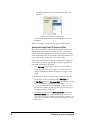
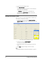
Check System Global Parameters
Prior to loading the first routine or processing the first gage measurement file, you must ensure that the system global parameters are
set properly for your compensation requirements. You can check the
default system global parameters, and if desired, you can change
them, in the System Configuration window.
More:
"System Global Parameters" (page 48)
40
Initializing the AutoComp System
Configuring the AutoComp
System
Configuring the AutoComp System: Overview
Configuring the AutoComp System consists of specifying variables
in either (or both) the User Options window or the System Configuration window.
User Options window variables. The variables that you set in the
User Options window are:
l
"Security Levels" (page 43)
l
"Operation Modes" (page 44)
l
"Specifying Temporary Setup Overrides" (page 45)
l
"Force Front on Cycle Complete" (page 46)
l
"Access AutoComp from CEI Remote View" (page 47).
Systems Configuration window variables. The variables that
you specify in the System Configuration window are: l
"Routine Path" (page 53)
l
"System Global Parameters" (page 48)
l
"Cycle Notifications" (page 71)
l
"Run Data Variables" (page 54).
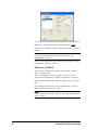
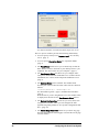
User Options Window
To get to the User Options window, in the Main Window tool bar,
press Configuration.
The User Options window is displayed.
Configuring the AutoComp System
41
User Options Window in Production Mode (Supervisor Level)
The User Options window provides the following functionality:
42
l
You can specify security level (Access Level). See "Security
Level" (page 1).
l
You can specify Operation Mode. See "Operation Mode"
(page 1).
l
The Force Front checkbox lets you set AutoComp so that the
Main Window comes to the front of your desktop when a cycle
completes. See "Force Front on Cycle Complete" (page 1).
l
The Run Remote Client checkbox lets you configure AutoComp to be monitored with CEI Remote View (contact CEI for
information). See "Access AutoComp from CEI Remote View"
(page 1).
l
The Machine Name field is editable. The machine name
becomes part of the run data file name. These files are named as
follows:
<routine(machine)> <timestamp>.csv
See "Run Data Log Files" (page 1) and"Run Data Variables"
(page 1).
Note also that if you are using Remote View, the machine name
is displayed in the title bar. See Run Remote Client (above).
l
The System Configuration button lets you access the System
Configuration window, where you can configure file management and global parameters. See "System Configuration Window" (page 47)
l
The Delete Gage Data Files button lets you delete any gage
data files that match the defined gage converter filter in all gage
converter folders.
Configuring the AutoComp System
l
The List Gage Converter Folder Files button lets you list all
files in the gage converter folders.
Security Levels
AutoComp has two security levels:
l
Operator Level restricts access to system configuration parameters and editing routines. At operator level, you can load and
unload routines and view current offset data and data log files.
l
Supervisor Level access allows all operations. You must enter
a password for supervisor level access. Press Supervisor Level
in the Main Window tool bar and then enter your password in
the keyboard that appears.
You can set security level and change the supervisor’s password in
the User Options window.
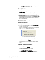
Setting Security Level
Set security level as follows.
1. Go to the User Options window by pressing Configuration in
the Main Window tool bar.
The User Options window is displayed. You set security level
in the Access Level section in the upper left.
User Options Window Access Level Section
2. Press the radio button next to the desired security level.
3. When you are through setting this and other variables in the
User Options window, press Apply.
Your specifications are saved and the User Options window
closes.
Changing Supervisor’s Password
To change the supervisor password:
1. Set the security level to Operator.
The Supervisor Password section appears.
2. Click Change Supervisor Password.
The New Password and Verify Password fields appear.
Configuring the AutoComp System
43
Supervisor Password Fields
3. Type the new password in the New Password field.
4. Retype the new password in the Verify New Password field.
5. When you are through setting this and other variables in the
User Options window, press Apply.
Supervisor Login
1. In the Main Window tool bar, click Supervisor Level.
A keyboard appears.
2. Use the keyboard to type your password, and press OK.
The tool bar now shows all available buttons.
Operation Modes
AutoComp has two operation modes: production mode and setup
mode.
l
In Production Mode, AutoComp analyzes gage measurements
automatically. In this mode, AutoComp loads the proper routine
if it is not already active, suspends a formerly active routine if
necessary, performs compensation calculations, and updates CNC
offsets, the Data Grid, and the History Chart.
l
In Setup Mode, as in production mode, AutoComp loads and
suspends routines. However, while in setup mode, any dimension
can be re-measured until its cycle or subcycle is accepted or cancelled. Re-measurement overwrites the data, in effect cancelling
the old measurement for that dimension.
Unlike production mode, compensation data remains in the
Active column of the Data Grid until the operator accepts or
cancels the cycle, using one of the two buttons that are displayed in the Run Screen tool bar, only in setup mode:
o
44
Accept sends the compensations to the CNC. The Data
Grid and the History Chart are updated.
Configuring the AutoComp System
o
Cancel discards the cycle of data and clears the Active column of the Data Grid.
In setup mode, you can choose temporary setup overrides.
More:
"Choice of Operation Mode" (page 88)
"Manual Gaging Buttons (Setup Mode Only)" (page 92)
Setting Operation Mode
To set operation mode:
1. Go to the User Options window by pressing Configuration in
the Main Window tool bar.
The User Options window is displayed.
2. Press the radio button next to the desired operation mode (in the
upper right section of the window).
Operation Mode Section of User Options Window
3. When you are through setting this and other variables in the
User Options window, press Apply.
Your specifications are saved and the User Options window
closes.
Specifying Temporary Setup Overrides
If you choose Setup as your operation mode, temporary setup override options are displayed in the Operation Mode section of the
User Options window.
Configuring the AutoComp System
45
Operation Mode Section of User Options Window
l
Disable Trend/Skip. Check this to temporarily ignore dimension skip and trend settings during setup.
l
Comp All Dimensions. Check this to temporarily ignore system
flags to NOT compensate rejected dimensions or dimensions that
exceed the wear limit during setup.
l
Setup Cycles. Select the number of cycles to run in setup mode
before automatically switching to production mode. The default
(0) means that you must manually switch to production mode
when you are ready.
When you are through setting this and other variables in the User
Options window, press Apply.
Your specifications are saved and the User Options window closes.
Force Front on Cycle Complete
You can configure AutoComp so that the Main Window comes to
the front of your desktop when a cycle completes. To do this, check
Force Front on the right hand side of User Options window.
Force Front Check Box on User Options Window
When you are through setting this and other variables in the User
Options window, press Apply.
Your specifications are saved and the User Options window closes.
46
Configuring the AutoComp System
Access AutoComp from CEI Remote View
You can configure AutoComp to be monitored with CEI Remote
View (contact CEI for information).
To do this, check Run Remote Client in the lower left of the User
Options window.
Run Remote Client Check Box on User Options Window
Note that the Machine Name field is editable and is displayed in
the title bar in Remote View. Also note that the machine name is
contained as part of the run data log file name, .
When you are through setting Run Remote Client and Machine
Name, as well as other variables in the User Options window, press
Apply.
Your specifications are saved and the window closes.
For more information on running a remote client, contact Caron
Engineering.
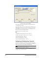
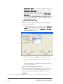
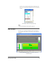
System Configuration Window
The System Configuration button in the User Options window
takes you to the System Configuration window.
System Configuration Window
Configuring the AutoComp System
47
When you are configuring the AutoComp system, this window lets
you view or change the routine storage path, specify run data file
locations, set system global parameters, and set AutoComp cycle
notifications.
The following descriptions walk you through each section of the
System Configuration window:
l
"Gage and CNC Definitions" (page 48)
l
"System Global Parameters" (page 48)
l
"AutoComp Cycle Notifications" (page 52)
l
"Routine Path" (page 53)
l
"Run Data Variables" (page 54)
Note: When you are initializing the AutoComp System, this window takes you to sub-windows where you can set gage and CNC
variables. More:
"Initializing the AutoComp System" (page 19)
Gage and CNC Definitions
Gage Converters and CNC System Buttons
in Sys. Config Window
These buttons take you to sub-windows where you can set gage and
CNC definitions.
More:
"Initializing the AutoComp System" (page 19)
System Global Parameters
You can set the system global parameters in the System Configuration window. 48
Configuring the AutoComp System
System Global Parameter Section of Sys. Config Window
The parameters that are selected (“checked”) by default are:
l
Clear Offset On Tool Change
l
Wear Offset Compensation
l
Dimension Limits as Deviation.
Note: Load Routine Variable is only available with Focas and
Okuma P200 (Lathe and Machining) controls.
All of the system global parameters are discussed in the following
sections.
Comp On Reject Parameter
This determines how the system handles out-of- tolerance dimensions. If this value is checked, the system will perform the compensation algorithm for the entire cycle, even if a dimension is out
of tolerance.
If unchecked, and a single dimension is outside its reject limits,
no compensation will be done for any dimension in the cycle (for a
single gage routine) or subcycle (for a multi-gage routine).
Comp Rejected Dimensions
This determines whether or not rejected dimensions are compensated
(only used if CompOnReject is true).
If this value is checked (and CompOnReject is also checked),
then dimensions outside their reject limits are compensated.
Comp After Wear
This determines whether AutoComp will continue to compensate a
tool after its wear limit as defined in the routine has been reached.
If checked, compensation will continue on dimensions that have
exceeded their wear limit.
Configuring the AutoComp System
49
Clear Offset On Tool Change
This determines if the CNC offset is cleared (set to 0) when an operator clears an AutoComp dimension tool life (either from the Tool
Change button of the Run Time Details View, or the Tool Life
Indicator on the History Chart).
If checked (default), the CNC offset will be cleared when the AutoComp tool life is reset (for Focas, DNC2, and Okuma P controls).
Expire Tool On Wear Limit
This determines if the CNC tool life management Tool Expired (or
NG) flag is set when a dimension has exceeded its wear limit. Only valid if the CNC is using tool life management, and for dimensions with ToolGroup/GroupOffset values set. (Currently used with
Okuma P and Focas controls only.)
Wear Offset Compensation
This determines whether AutoComp writes compensation data to the
tool offset (or geometry) of the CNC, or to the tool wear offset (if
available).
If checked (default), tool wear offsets are written.
Log Level
This is for support purposes only, and should remain the default
value of 0. Skip Count and Skip Trend Functionality
Skip Count sets the number of compensation cycles to skip processing in an automated environment where a delay is required
between production of a part and its gaging.
A value of 0 is the default skip count. You can set the default skip
count for new routines on the System Configuration window.
The skip count is initiated on a dimension only after a compensation is produced.
If a routine is suspended, the current skip value for each dimension
is saved, and used to initialize the skip on the next routine load. If a routine is unloaded, the skip is initialized for each dimension on
the next load, as defined in the Dimension Parameters tab of the
Edit window .
Skip/Trend Functionality:
Skip and trend interact as follows:
l
50
There is no skip on a dimension until a compensation is
produced.
Configuring the AutoComp System
l
From that compensated cycle, for skip cycles, everything pertaining to that dimension is ignored, meaning that there are no
updates to wear, trend buffer, etc.
l
At the end of skip cycles, functionality returns to 'normal' as if
there was no skip.
l
Trending continues until the next cycle that produces a compensation for the dimension, at which time the skip functionality
is initiated again for that dimension.
More:
"Trend" (page 79)
"Units and Cpk" (page 71)
Viewable Data Cycles
This lets you set the number of data cycles that are viewable in the
Data Grid.
A Viewable Data Cycles value of 10 is the default for each newly
created routine.
In the History Chart and Data Grid, ten cycles can be viewed at a
time, but if you set the number of data cycles to more than ten, a
scroll bar lets you scroll through the cycles. The last cycle (represented by the right-most square “point”) in the graph corresponds
to the last column in the data grid below the graph.
Note: The more cycles are viewable in the grid, the LONGER it
will take to load a routine, as the grid must be filled with the historical data. This could affect processing time, and should be tested
by the user/operator, to find an acceptable balance.
More:
"Working with Run Data" (page 85)
Dimension Limits Deviation
This determines whether tolerance and compensation values are
entered as deviations from the dimension nominal when editing a
dimension/routine.
If checked (default), they are entered as deviations. Otherwise, they
must be entered as actual values.
Offset Display As Deviation
This controls whether actual gage values are displayed as deviations
from the nominal in the Data Grid.
If checked, they are displayed as deviations. Otherwise, the actual
gaged values are displayed as received from the gage.
Configuring the AutoComp System
51
Trend Reset Time and Trend Reset Over
If AutoComp has not received data in the time set in the Trend
Reset Time field, the trend is reset, for every routine newly-loaded
(first load only), for the trend reset period.
When you click in the Trend Reset Time field, a numeric keypad
appears allowing you to enter the minutes and seconds of the trend
reset period (in the format: min.sec, where "2.3" denotes two minutes and three seconds).
Trend Reset Over: This condition lasts for the trend reset period,
after which (assuming gage data is being processed) routines that
have not yet been loaded since trend reset began, will NO
LONGER have trend buffers reset on the first cycle.
You enter the Trend Reset Over value in a numeric keypad, just
as for Trend Reset Time.
Load Routine Variable
Load Routine Variable is only available with Focas and Okuma
P200 (Mill and Lathe) controls.
This system global parameter works in conjunction with the Routine Editor's AutoLoad Routine Value.
For detailed information, see "AutoLoad Routine Value" (page 70).
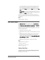
AutoComp Cycle Notifications
The AutoComp system permits you to pass macro variables to your
control when completing a cycle, compensating a dimension, and
exceeding the wear limit on a tool. (Note that these are defaults, and
can be changed, for any individual routine.)
AutoComp Cycle Notifications Section of Sys. Config. Window
52
Configuring the AutoComp System
The cycle notifications are discussed in the sections that follow.
Cycle Complete
This CNC macro or common variable is set on each cycle completion.
If all dimensions in a cycle were measured, the CycleComplete
value is set.
If any dimensions were missing measurements when the cycle finished, the Cycle Missing Dimensions value is set.
Note: If (due to error) a dimensions measurement field is not
numeric, the dimension will appear as a missing measurement. If the
missing dimension is marked as critical it will hold up the cycle
from completion. The routine can be manually unloaded to proceed.
Wear Limit Notification
This CNC macro or common variable is set on each cycle completion, when enabled.
If any dimension exceeds 100% of its tool life, the Wear
Exceeded value is set.
If all dimensions are within tool (wear) life limits, the Wear
GOOD value is set. A macro value of 0 (zero), means no macro/variable is set for
Good/Reject status.
Any individual dimension with a tool wear limit of 0 will not be
considered as ever exceeding its wear life. This is the default value
initially used by newly-created routines.
Compensation Ack
The Compensation Ack CNC macro or common variable is set on
each cycle completion. A macro value of 0 (zero) means that no
macro/variable is set for Good/Reject status. The value of 0 is the default value for newly-created routines.
If all dimensions in a cycle were within reject limits, the Cycle
GOOD value is set.
If any dimensions were outside reject limits when the cycle finished,
the Cycle Reject value is set.
Routine Path
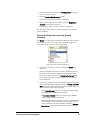
The Routine Path button lets you view or change the routine .ini
file location. Under most circumstances, this location should remain
the default.
Configuring the AutoComp System
53
Routine Path Button on Sys Config Window
When you are through setting this and other variables, press OK.
Your specifications are saved and the System Configuration window closes.
Run Data Variables
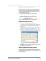
The buttons and fields in this section of the System Configuration
window let you specify:
l
RunData Main Path
l
ProcessData Tag Watch
l
ProcessData Tag as SubFolder
l
RunData Reset Times.
RunData Variables in System Configuration Window
Before looking at how to set these run data variables, it is important
to have an overview of how they are interrelated.
Run Data Files Overview
Main Path: Run data files are stored at a location designated using
the RunData Main Path button, and displayed next to that
button. ProcessDataTag is included as a new (last) column in the run
data files. It is a user-defined field that is associated with the process, and can be used, if desired, to name subfolders in which to store
run data.
SubFolders: Instead of using the main path, you can choose to
store the run data files in subfolders created under the main path (by
part or lot number for example) that change dynamically. 54
Configuring the AutoComp System
You can use the ProcessData Tag as SubFolder button to specify that a subfolder is to be used for storing process data (by dynamically changing the process data tag).
The process data tag is changed by a text file containing the new
process data tag:
AutoCompRunDataSubfolder.txt
This file is contained in a "watch" folder. The file has a single line
of text (which is the name of the process data subfolder to be
created off the main run data folder).
There are two ways these text files can be created:
l
You can create the text file manually. Note that a <CR><LF>
is required to end the tag.
l
You can use the CEI_COMTOFILE application for RS232-based
file drops (ie BarCodeReader), also requiring a <CR><LF> to
end the tag, or you can use the manual option of the CEI_COMTOFILE application. ProcessData Tag Watch. You use the ProcessData Tag
Watch button to set the folder that AutoComp is to watch for process data tag change files. The path is displayed next to the button.
Run Data file names. The format of run data file names is as follows:
<routine name>(<machine name>)_<creation time
stamp>.csv
Run data files can be imported into Excel.
More:
See "Note: Run Data Detail" (page 55), for more detailed information about run data files.
Note: Run Data Detail
As always (and as noted in AutoComp Release Notes change 1.8.21)
a new run data file signals a process context change, and resets the
Cpk to N/A for the next four cycles. The other historical data for
loaded or suspended routines will remain intact. If the run data folder is a network share that becomes unavailable,
AutoComp (and DataCollect) will automatically and temporarily
use the run data subfolder in the installation folder to store run data
information, and create subfolders there as needed (if the ProcessData Tag As SubFolder option is used). Under this condition, each time a new run data file is opened (from an unloaded or
suspended routine being reloaded, or a run data lifetime expiration,
or a run data subfolder change), an attempt will be made to reconnect to the network share, and if successful, run data files will be
stored there. Run data files created locally while the network share
was down will remain local until manually moved.
Configuring the AutoComp System
55
Note that there is the possibility of losing one cycle of data when
the network share becomes unavailable.
While the network share is unavailable, a new run data file will be
created every time a routine is loaded, whether is was previously
unloaded (which normally starts a new run data file) or suspended
(which normally appends the last run data file). On every routine
load, the network share will attempt to be accessed as the target of
the run data, and a failure results in a new "local" file being started.
Run Data Main Path
Run data files (AutoComp historical data based on routine and
machine names) can be stored anywhere on the network. (See "Run
Data Files Overview" (page 54), for more information.)
The RunData Path Main Path button lets you specify where run
data files will be stored.
RunData Main Path Button on Sys Config Window
When you are through setting this and other variables in the User
Options window, press OK.
Your specifications are saved and the System Configuration window closes.
Current Data Tag and Process Data Tag Watch
Current Data Tag:
The current label logged with each cycle as the data tag in the run
data file. If you are using subfolders, this is the name of the subfolder that run data files are created in.
Process Data Tag Watch:
The Process Data Tag Watch button lets you specify the folder
to “watch” for process data tag change files. (See "Run Data Files
Overview" (page 54), for more information.)
ProcessData Tag Watch Button in Sys. Config. Window
After you have chosen or created a folder and pressed OK, the
folder and path are displayed in the System Configuration window:
56
Configuring the AutoComp System
ProcessData Tag Watch Button with Folder and Path
Process Data Tag as SubFolder
You can choose to store run data files in a subfolder off the RunData Main Path. The subfolder is named by the current process data tag, and changes
when a new process data tag change file appears.
To store run data files in a subfolder, check the ProcessData Tag
as SubFolder checkbox.
ProcessData Tag as SubFolder Checkbox
When you are through setting this and other variables in the System
Configuration window, press OK.
Your specifications are saved and the System Configuration window closes.
(See "Run Data Files Overview" (page 54) for more information.)
Run Data Reset Days, Hours, and Minutes
The Run Data Reset fields allow you to set the lifetime of run
data files by days:hours:minutes. There is a 0->60 second resolution on this lifetime, as files are checked every minute for
expirations. If all fields are 0 (zero) the run data file continues to append data
until the routine is unloaded.
If the Run Data Reset fields are used, a run data file for a routine
will be closed and a new run data file started when the specified
reset time expires (based on the file creation time). This will continue until the routine is unloaded.
When you press in any of the Run Data Reset fields, a numeric
keypad appears that lets you specify the desired run data file lifetime in days, hours, and minutes.
Run Data Reset Times Fields in the Sys. Config. Window
Configuring the AutoComp System
57
Note : If the ProcessDataTagAsSubFolder option is used and
the target run data folder changes, a new run data file is started. When you are through setting these and other variables in the System Configuration window, press OK.
Your specifications are saved and the System Configuration window closes.
58
Configuring the AutoComp System
Creating and Editing Routines
Creating and Editing Routines: Overview
This chapter gives step-by-step instructions for creating and editing
routines. It does not give detailed information on routine or dimension parameters. For this information, go to "Global Routine Parameters" (page 69) and "Dimension Parameters" (page 74). It also does
not give detailed information on how routines function. For this
information, go to "AutoComp Functionality" (page 5).
The sections in this chapter are:
l
"Creating a Routine" (page 59), which explains the first step in
creating a routine
l
"Using the Edit Window" (page 60), which explains how to
enter routine and parameter information for both new routines
and existing inactive routines
l
"Using the Detail Chart" (page 68), which explains how to edit
an active routine.
Creating a Routine
To create a routine, you must name the routine, specify routine
parameters and dimension parameters in the Edit window, and then
save the routine. When you save the routine in the Edit window,
AutoComp creates an .ini file containing all of the parameter
information.
Naming the Routine
The names of routines and gage data files are crucial in AutoComp’s ability to detect and load routines, so before you attempt to
create a routine it is important that you read the"AutoComp Functionality" (page 5), which explains how AutoComp uses routine
names.
Creating and Editing Routines
59
1. In the Main Window toolbar, press Create Routine.
2. Type the routine name in the keypad that appears, and then
press OK.
The Edit window appears, in the Routine Parameters tab.
2. Enter all routine parameter information in this tab, and then go
to the Dimension Parameters tab and enter all necessary information there.
More:
"Global Routine Parameters and Dimension Parameters" (page 69)
"How AutoComp Selects and Loads a Routine Automatically"
(page 6)
Using the Edit Window
You use the Edit window to enter dimension parameter and routine
parameter data, in both new and already existing, inactive routines. The Edit window has two tabs: a Routine Parameters tab and a
Dimension Parameters tab.
This section gives you the basics for using both tabs of the Edit window. Note that you can also edit dimensions in an active routine in
the Detail Chart.
More:
For detailed information on dimension and routine parameters, see
"Global Routine Parameters and Dimension Parameters" (page 69).
For information on editing an active routine, see "Using the Detail
Chart" (page 68).
Editing Routine Parameters in the Edit Window
Routine parameters are also called “global” parameters because they
affect all dimensions in a given routine (unlike dimension parameters, which only affect specific dimensions).
If you are editing an existing routine, the values you enter in the
Routine Parameters tab of the Edit window will override system
configuration variables and previously entered values for the routine.
This section outlines the routine parameters and explains the control
buttons. For detailed information on routine parameters, see "Global
Routine Parameters and Dimension Parameters" (page 69).
To go to the Edit window's Routine Parameters tab:
60
Creating and Editing Routines
l
If you are creating a new routine, as soon as you have named
the routine, the Edit window appears, in the Routine Parameters
tab (see below).
l
If you are editing an existing routine, press the Edit Routines
button on the Main Window tool bar, and select the routine from
the Select Routine window.
The Edit window appears, in the Routine Parameters tab.
AutoComp Edit Routine Window, Routine Parameters Tab
More:
For detailed information on routine parameters, see "Global Routine
Parameters and Dimension Parameters" (page 69).
Edit Routine Parameters
The Edit window's Routine Parameters tab lets you:
l
Specify Variable Path/Subsystem
l
Specify AutoLoad Routine Value (only available for Focas and
Okuma P200 controls)
l
Select Units (inch or millimeter) of all gage readings for the routine
l
Set Cpk if you want AutoComp to calculate Cpk and store it in
a run data file as well as display it in the live Data Grid
l
Set the AutoComp Cycle Notification variables
l
Set the Gage Required Counter variables.
Note: For an existing routine, the values you enter will override the
system configuration values and the values previously entered for
the routine.
Creating and Editing Routines
61
More:
"Path/SubSystem" (page 72)
"Units and Cpk" (page 71)
"Cycle Notifications" (page 71)
"Gage Required Counter" (page 73)
Edit Routine Control Buttons
The Edit window’s Routine Parameters tab includes the following control buttons:
l
Select Part View Picture. Part View is an AutoComp operation mode that lets you view gage data in the context of an
actual picture of the part.
When you use Part View you need to load a picture of the part
into AutoComp. Use this button to browse to the file you want
to use in Part View for the routine. It must be a .jpg file. The
file is then displayed in the button:
Select Part View Picture Button with Image Selected
You can still press the button with the picture in it, if you want
to browse again to a different .jpg file.
l
Save Routine - The Save Routine button saves all edits to the
routine (including edits made in the Dimension Parameters tab)
and closes the Edit window.
l
Cancel All Edits - The Cancel All Edits button aborts all edits
to the routine and closes the Edit window.
IMPORTANT: Even saved dimensional edits are aborted.
More:
"Global Routine Parameters and Dimension Parameters" (page 69)
Editing Dimension Parameters in the Edit
Window
A dimension is one set of measurements of a part that is tooled in a
routine. All measurements that require tool compensation for the
part should be defined in a routine. This section gives you the
62
Creating and Editing Routines
basics for using the Dimension Parameters tab, which lets you edit
dimensions in routines that are not active.
In the Edit window, select the Dimension Parameters tab (shown
below), to program dimension parameters.
AutoComp Edit Routine Window, Dimension Parameters Tab
More:
For detailed information on dimension parameters, see "Global Routine Parameters and Dimension Parameters" (page 69).
For information on editing dimensions in an active routine see
"Using the Detail Chart" (page 68)
Edit Dimensions Control Buttons
With the exception of the Rename field, the Edit window’s dimension parameters control buttons are on the right side of the Dimension Parameters tab.
Creating and Editing Routines
l
Rename - This button, next to the Dimension Name field, lets
you rename the current dimension.
l
MoveDimIndex Up/Down - The display order indicates the
order in which dimensions will be displayed on the Run Screen.
Use the MoveUp/MoveDown buttons to re-order the dimensions.
l
CopyData/PasteData - Use these buttons to copy data from
selected dimension or paste previously copied data into selected
dimension.
l
Duplicate Dimension. Use this button to create a duplicate of
the current dimension, with a different name. When you press
Duplicate Dimension, the name of the current dimension is
63
displayed in the DimensionName field, followed by an underscore “__”. You can rename the new dimension as you wish.
l
New Dimension. Use this button to add a new dimension.
l
Delete Dimension. Use this button to delete the currently
selected dimension.
l
Save Dimension - When you have finished editing parameters,
you press the Save Dimension button to confirm the edits
before going on to another dimension. A message will notify
you if you fail to do so.
l
Undo Dimension - The Undo Dimension button returns parameter values to the last saved setting. Once the dimension has
been saved, this button is unavailable.
l
Save Routine - The Save Routine button saves all edits to the
routine and closes the Edit window.
l
Cancel All Edits - The Cancel All Edits button aborts all edits
to the routine and closes the Edit window.
IMPORTANT: Even saved dimensional edits are aborted.
l
Save Routine As - This creates a duplicate of the routine by
saving it to another name. You can then edit the routine as
needed. You then must SAVE the edits to save the routine as its
new name.
To Edit Dimension Parameters in an Existing
Routine
To edit dimensions in an existing routine that is not active, follow
these steps:
1. Press Edit Routines in the Main Window toolbar.
The Select Routine list box is displayed.
2. Select the desired routine and press OK.
The routine is displayed in the Edit window.
3. Click on the Dimension Parameters tab.
4. Select the dimension you wish to edit by pressing the arrow
next to the Dimension Name fieldand selecting the dimension
from the drop-down list.
5. Enter general parameters for the dimension as follows:
l
Press the parameter to display a data entry keypad.
l
Enter a value using the data entry keypad and press OK.
Your new values will replace the old ones.
(See "General Dimension Parameters" (page 75), for information
on each parameter.)
64
Creating and Editing Routines
6. If you wish, press the Tool Compensation checkbox to enable
tool compensation for the dimension. Otherwise skip to step 7.
If you enable tool compensation, you may enter values for compensation parameters and machine parameters. The new values
you type in the data entry keypad replace the old ones.
7. Press Save Dimension when you are finished entering parameter values.
The new parameter values are saved.
8. You may edit more dimensions by repeating steps 3-7.
9. When you have entered your final dimension, press Save Routine.
More:
"Global Routine Parameters and Dimension Parameters: Overview"
(page 1)
Adding a Dimension to an Existing Routine
A dimension is one set of measurements of a part that is tooled in a
routine. For more detailed information on dimensions, see "Global
Routine Parameters and Dimension Parameters" (page 69).
There are three ways to add a dimension to an existing routine. You
can:
l
Add a dimension “from scratch,” entering all information manually. See "To Add a Dimension to an Existing Routine from
Scratch" (page 65).
l
Add a dimension by using the Duplicate Dimension control
button. See "To Add a Dimension Using Duplicate Dimension"
(page 66).
l
Add a dimension by copying and pasting an existing dimension,
and then editing it as needed. See "To Add a Dimension Using
Copy and Paste" (page 67).
You use the control buttons in the Dimension Parameters tab of the
Edit window, to add new dimensions.
To Add a Dimension to an Existing Routine
from Scratch
You may add a dimension to an existing routine in the Edit window's, Dimension Parameters tab, using these steps:
1. In the Main Window tool bar, press Edit Routines.
The Select Routine list box is displayed.
2. Select the desired routine and press OK.
Creating and Editing Routines
65
The routine is displayed in the Routine Parameters tab of Edit
window.
3. Go to the Edit window's Dimension Parameters tab.
4. Press the New Dimension control button.
The Input Dimension Name keypad is displayed.
5. Enter the name of the new dimension and press OK.
The new dimension name is displayed in the Edit window, in
the Dimension Name field.
5. Enter general parameters for the new dimension as follows.
For each parameter:
a. Press the parameter to display a data entry keypad.
b. Enter the value in the data entry keypad.
c. Press OK. In the keypad to return to the Edit Routine window.
See "Global Routine Parameters" (page 69) for information on
each parameter.
6. If you wish, press the Tool Compensation checkbox to enable
tool compensation for the dimension. Otherwise skip to step 7.
If you enable tool compensation, you may enter values for compensation parameters and machine parameters.
7. Press Save Dimension when you are finished entering parameter values.
The dimension with its associated parameters is added to the
routine. It is the last dimension in the routine’s list of dimensions. Use Move Up if you wish to change its order in the
dimension list.
You must press the Save Routine button in order for the
dimension to be saved.
To Add a Dimension Using Duplicate Dimension
You can add a new dimension to a routine by duplicating the current dimension.
1. In the Main Window tool bar, press Edit Routines.
The Select Routine list box is displayed.
2. Select the desired routine and press OK.
The routine is displayed in the Routine Parameters tab of Edit
window.
66
Creating and Editing Routines
3. Go to the Edit window's Dimension Parameters tab.
4. In the Edit window's Dimension Parameters tab, press the Duplicate Dimension control button.
The name of the current dimension is displayed in the DimensionName field, followed by an underscore “__”. This dimension has all of the same values of the dimension it duplicates.
5. You can Rename the new dimension as you wish. You can
also edit the dimension as needed.
6. Press Save Dimension when you are finished entering parameter values.
The dimension with its associated parameters is added to the
routine. It is the last dimension in the routine’s list of dimensions. Use Move Up if you wish to change its order in the
dimension list.
You must press the Save Routine button in order for the
dimension to be saved.
To Add a Dimension Using Copy and Paste
You can copy a dimension and then create another dimension in the
same routine with the same parameter values. (You can then edit the
dimension as needed.)
1. In the Main Window tool bar, press Edit Routines.
The Select Routine list box is displayed.
2. Select the desired routine and press OK.
The routine is displayed in the Routine Parameters tab of Edit
window.
3. Go to the Edit window's Dimension Parameters tab.
4. Use the down arrow next to the Dimension Name field to display the desired dimension. 5. When the dimension you want to copy is displayed, press Copy
Data.
6. Press Add New Dimension.
The Input Dimension Name keypad is displayed.
4. Enter the name of the new dimension and press OK.
The new dimension name is displayed in the Edit window, in
the Dimension Name field.
5. Press Paste Data.
The values from the dimension you copied are pasted into the
new dimension’s fields.
Creating and Editing Routines
67
6. If you wish, edit the parameter values.
7. Press Save Dimension.
The dimension is added to the routine. It is the last dimension
in the routine’s list of dimensions.
Use Move Up to change its order in the dimension list.
You must press the Save Routine button in order for the
dimension to be saved.
Using the Detail Chart
The Detail Chart lets you edit a limited number of variables in an
active routine. To edit an active routine:
1. In the routine’s Run Screen, press the View Details>View
Grid>View Chart toggle button, so that the Detail Chart is displayed.
Detail Chart, Showing Data Entry Keypad
2. In the Detail Chart, press Edit Parameters.
Values that can be edited appear in bold.
3. Press the desired field to open a keypad where you can enter
values.
4. Press Apply to apply the changes to the active routine.
More:
"Global Routine Parameters and Dimension Parameters" (page 69)
68
Creating and Editing Routines
Global Routine Parameters
and Dimension Parameters
Global Routine Parameters and Dimension
Parameters: Overview Part routines contain two kinds of parameters: routine parameters
(also called global parameters), and dimension parameters. The information you enter for a routine parameter is “global” because it
applies to all the dimensions in a routine. Dimension parameters
apply to a single dimension.
Global Routine Parameters
Routine parameters are “global” because they apply to all the dimensions in a routine. The routine parameters are available in the Edit
window’s Routine Parameters tab. You can save all edits to the routine, or cancel all edits (including all dimension changes) from this
window.
Global Routine Parameters and Dimension Parameters
69
Edit Window’s Routine Parameters Tab
These variables are discussed in the sections that follow.
AutoLoad Routine Value
The AutoLoad Routine Value parameter is available with Focas
and Okuma P200 controls.
The value you enter in this field works in conjunction with the System Configuration window's global parameter, Load Routine Value.
70
l
If the System Configuration window's Load Routine Value is 0,
this variable is ignored.
l
If the Load Routine Value is -1 and a routine is already loaded,
the routine is unloaded (not suspended). Any routine subsequently loaded either by a gage file or manually, will also be
unloaded, until the Load Routine Value variable is no longer -1.
l
If the System Configuration window's Load Routine Value
matches the Routine Editor's AutoLoad Routine Value, then the
routine will be loaded if:
o
it is not already loaded,
o
it is not being edited (in which case it will be loaded as
soon as the editor is closed),
o
the currently loaded routine is not in mid-cycle, waiting for
critical measurements for the cycle to complete (in which
Global Routine Parameters and Dimension Parameters
case, it will be loaded as soon as the cycle completes the currently loaded routine).
The routine will continue to reload if manually unloaded or suspended (or suspended by a load of a gage data file for another
routine) until the CNC variable value changes.
More:
"Load Routine Variable" (page 52)
Units and Cpk
The upper left hand section of the Edit window’s Routine Parameters tab contains the following variables.
Units, and Cpk Fields
Units
Sets the units (millimeter or inch) in which AutoComp is to interpret the gage data. Millimeters are rounded to four decimal places
and inches are rounded to five decimal places.
Cpk
Process capability index desired. This value is calculated on a per
dimension basis and reported in the Cpk column of the Data Grid
and stored in the run data file.
If absolute value of URL=0 then Cpk=Cpl and if absolute value of
LRL=0 then Cpk=Cpu. Otherwise Cpk is the min as the standard
equation defines.
For more information see "Run Data Variables" (page 54).
Cycle Notifications
The AutoComp Cycle Notifications section of the Edit window’s
Routine Parameters tab contains the following variables.
Cycle Notification Variables in Edit Window
Global Routine Parameters and Dimension Parameters
71
These variables:
l
Path/SubSystem
l
Cycle Complete variables
l
Comp Ack variables
l
Wear Limit Notification variables
are initially set to system global configuration values and can be
changed in each routine.
Path/SubSystem
This refers to the path/turret that is used as the target for variable
feedback.
Cycle Complete Variables
There are three Cycle Complete variables.
l
Cycle Complete Macro: CNC macro or common variable set
on each cycle completion
l
Cycle Complete: If all dimensions have been measured when
the last routine dimension is processed (signaling a complete
cycle), then the "Cycle Complete" value is written to the
machine variable. l
Cycle Missing Dimensions: If any dimension measurements are
"Missing" on cycle completion, the "Cycle Missing Dimensions"
value is written. If, due to error, a measurement field contains
non-numeric data, it will appear as "Missing."
Wear Limit Notification Variables
There are three Wear Limit Notification variables.
l
Wear Limit Macro. CNC macro or common variable set on each
cycle completion. A macro value of 0 (zero), means no macro/variable is to be set for wear limit status. Any individual dimension
with a tool wear limit of 0 will not be considered as ever exceeding its wear life. Default values for this parameter are defined in
the system configuration process. (See "System Global Parameters" (page 48).)
l
Wear Exceeded. If any dimension has exceeded 100% of its
tool life, the ‘Wear Exceeded’ value is set.
l
Wear GOOD. If all dimensions are within tool life limits, the
‘Wear GOOD’ value is set.
Comp Ack Variables
There are three Comp Ack variables.
l
72
Comp Ack Macro. CNC macro or common variable set on each
cycle completion. A macro value of 0 (zero) means no
Global Routine Parameters and Dimension Parameters
macro/variable is to be set for Good/Reject status. Default
values for this parameter are defined in the system configuration
process.
l
Cycle Has Reject. If any dimension in the cycle was outside of
the upper or lower reject limits, the ‘Cycle has Reject’ value is
set.
l
Cycle GOOD: If all dimensions are within reject tolerances, the
‘Cycle GOOD’ value is set.
Gage Required Counter
The gage required counter reads variable containing the number of
cycles before alerting the operator that gaging is required. The Gage Required section of the Edit window’s Routine Parameters tab contains the following variables:
Gage Required Counter Fields
l
The Gage Required Macro is the variable to be monitored by
AutoComp, and changed by the CNC program to track parts and
signal when gaging is required. The part program must set this
variable after every part. AutoComp will never set (or zero out)
this parameter; it only polls it and shows the operator the current
part count, compared to the count that requires gaging. (See note
below.)
l
Gage Required Count is the number at which the operator
should gage a part. (See note below.)
l
Gage Required Timer specifies how often to poll the machine
to read the next cycle.
Note:
In the Run Screen's status bar, the Count/Required field lists both
the Gage Required Count value ("Count"), which you set here,
and the Gage Required Macro variable VALUE ("Required"). The
color in which the Count/Required data are displayed is dependent on the value:
l
Green = 0 to 75% from actual
l
Yellow = 76% to 95%
Global Routine Parameters and Dimension Parameters
73
l
Red = higher than 95%.
More:
"Run Screen Tool and Status Bar" (page 90)
"Count/Required" (page 91)
Dimension Parameters
Dimension parameters apply only to a specific dimension. You can
set dimension parameters in the Edit window’s Dimension Parameters tab.
Dimension Parameters Tab in Edit Window (with Tool Compensation Selected)
There are two types of dimension parameters to define:
l
General parameters, which must be set for each dimension,
whether or not tool compensation is enabled.
l
Compensation parameters (including tool parameters), which can
only be set if tool compensation is enabled.
General parameters are discussed below. For information on compensation parameters, go to page 77.
74
Global Routine Parameters and Dimension Parameters
General Dimension Parameters
AutoComp includes the several general dimension parameters for a
dimension. These parameters can be edited in the upper left section
of the Edit Routine window.
General Dimension Parameters (Detail of Edit Window's Dimension Parameters Tab)
These general parameters are discussed in the sections that follow.
Dimension Name
Specify a name for the dimension.
You can also rename an existing dimension using the Rename button to the right of the name.
Dimension Index
This is the ordinal number (first, second, third, etc.) of the dimension
within the routine. This is not editable. You can, however, change
the order of dimensions in a routine, using the Move Dimension
Up or Down buttons in the Edit window's Dimension Parameters
tab.
Gage Converter
The gage converter is used to define the gage data file format and
present measurement data to AutoComp. Gage converters are
defined in the system configuration process.
The Gage Converter variable in the Edit window displays a dropdown list showing all of the gage converters that have been defined
From the dropdown list, select the converter you wish to associate
with this dimension.
Gage Converter Dropdown List (Detail of Edit Window's Dimension Parameters Tab)
Global Routine Parameters and Dimension Parameters
75
More:
"Gage Converter Configuration: Overview" (page 33)
Tool Compensation Checkbox
Check this parameter if you want AutoComp to compensate an offset or variable location when appropriate.
When you enable tool compensation by checking this parameter,
you may then enter compensation parameters and tool parameters.
More:
"Compensation Parameters" (page 77)
Nominal
The Nominal value is the ‘perfect’ gage measurement for a part. It is
represented in AutoComp’s History Chart as the central, unchanging horizontal green line.
Row
Indicates what row of the gage data file (or what consecutive element in a set column file) corresponds to this dimension. The column of actual data measurement varies depending on the gage
interface.
Upper/Lower Reject Limit
Select your tolerance limits for the dimension. Set this to the deviation from nominal or absolute value, depending on the system
dimension limits deviation flag.
The reject limits are represented by horizontal red lines on the History Chart. Gaged dimensions which exceed the reject limits are
shown in red on the Data Grid. Upper or lower reject limits can be marked 'not applicable' in the
Routine editor, which simply sets a + or - .000001 tolerance from
the nominal for that reject limit.
Note: Set this to the deviation from nominal or absolute value,
depending on the system dimension limits deviation flag.
Cycle Complete Critical Each routine needs at least one “critical” dimension for a cycle of
data to be completed and for AutoComp to accept the next cycle. A cycle completes when all critical dimensions have data associated
with them. Any other (non-critical) dimensions that do not have
data yet will be marked missing.
Note: If (due to error) a dimensions measurement field is not
numeric, the dimension will appear as a missing measurement. If the
76
Global Routine Parameters and Dimension Parameters
missing dimension is marked as critical it will hold up the cycle
from completion. The routine can be manually unloaded to proceed.
Compensation Parameters
When tool compensation is enabled, AutoComp provides several
compensation parameters. (To enable tool compensation for a dimension, check the Tool Compensation checkbox in the General
Parameters section of the Edit window’s Dimension Parameters
tab.) When Tool Compensation is checked, the compensation
parameters are displayed.
These parameters can be edited in the bottom left section of the
Edit window’s Dimension Parameters tab.
Edit Window's Compensation Parameters, with Tool Groups and
Cut Position (Detail of Dimension Parameters tab)
The compensation parameters are discussed in the sections that follow.
Upper/Lower Comp Limit
If the actual gaged value lies inside these two limits, the dimension
is deemed good and no compensation is performed. These values
should lie within the reject limits.
Set this to the deviation from nominal or absolute value, depending
on the system dimension limits deviation flag.
Gage values that lie outside the comp limit and inside the reject limits are sent to the CNC for compensation.
If your system is configured with CompOnReject = False, then no
comps are sent if a gage cycle (for single gage routines) or subcycle
(for multi-gage routines) contains a reject value.
Global Routine Parameters and Dimension Parameters
77
Comp Additive
Comp Additive (formerly referred to as "Comp Target") allows
AutoComp to anticipate process trends by compensating the CNC
back to a point above or below the nominal, so that the nominal is
the mean value, and there is an even two-sided distribution. This can also be used if the part is measured in a hot condition that
requires the desired dimension to deviate from the nominal in order
to anticipate the size reduction when the part cools.
The actual Comp Additive value is added to the calculated compensation value, before being sent to the CNC.
Set the value to zero, if a one-sided distribution is acceptable.
Example of target compensation: Assume the part tolerance is
+/-.001”, the compensation limit is+/-.0005”, and the Comp Additive is set to -0.0002”. If the part is measured with an error of +0.0003”, the normal calculation would send a -0.0003” to the tool offset. However, with a
Comp Additive of -0.0002”, the total value sent to the tool offset is
-0.0005”.
Note: CompByPercent changes the CompAdditive entry to percent of compensation.
More:
"Comp by Percent" (page 78)
Comp by Percent
CompByPercent changes the CompAdditive entry to percent of
compensation. This means that the final compensation, as well as
the trend buffer entry, is a percent of the calculated compensation.
More:
"Comp Additive" (page 78)
Tool Name
The user-defined name of the currently active tool. This can be programmed to indicate type of tool that is bound to dimension. This
variable can be left blank.
Tool Wear Limit
The system tracks the accumulated comps sent to a particular offset.
AutoComp displays wear tracking in the rectangular, colored panel
on the left side of the Run Screen. (See "Run Screen Basic Components" (page 89).
If the total comp range of the tool is known, the system can indicate
that this limit has been reached and warn the operator about possible dull tooling.
78
Global Routine Parameters and Dimension Parameters
Set this value to zero to turn off this feature.
The algorithm processes wear as an absolute value, so tool wear is
programmed as a positive value even if the machine is being offset
in a negative direction.
CNC Comp Limit
CNC Comp Limit allows system protection by programming a maximum comp value that is allowable for a dimension.
If the gage value evaluates to a greater comp value than this limit,
the comp is restricted to this maximum (unless this is a variable
dimension, with the Set Always flag set).
Program a zero to disable this feature.
This is evaluated as an absolute value and should be programmed as
a positive value.
More:
"Machine Variable Compensation Parameters" (page 82)
Trend
The trend is the number of gage readings used to calculate the running average. The running average removes noise from the system
by resolving irregularities in gage measurement caused by factors
other than tool wear.
For example, a trend of three means that the first three measurements
are averaged: then when the fourth measurement comes in, it
replaces the first measurement, which is dropped from the calculation. When the fifth measurement comes in, it replaces the second measurement, and so on.
The following graph shows grouping and compensation for a trend
of 3 in the third dimension. In this example, you would set trend to
zero or 1 to disable, or 2-10 to provide averaging.
History Chart: Grouping and Compensation for a Trend of Three
(Third Dimension)
Global Routine Parameters and Dimension Parameters
79
Skip
Skip count is the number of compensation cycles to skip processing
in an automated environment where a delay is required between production of a part and its gaging.
The default value for this parameter is one of the global parameters
defined in the System Configuration window.
For more information, see "Skip Count and Skip Trend Functionality" (page 50).
Axis
Set to desired axis. Axis, Turret, and Offset Number together specify tool offset.
Cut Position
If your machine is an Okuma Lathe, you can enter a cut position in
the Dimension Parameters tab of the Edit window.
Compensation Parameters, including Cut Position
80
Global Routine Parameters and Dimension Parameters
Tool Cut Position Window
Simply click in the CutPosition field to display the Tool Cut Position window. In the Tool Cut Position window, select the desired
cut position and press OK.
Tool Groups/Tool Group/Tool Offset
This option is only used by EasyComp or by Focas 1 or 2, or by
Okuma P if Okuma P is configured to support tool groups. It lets
you view and specify tool group and group offset information.
Check the Tool Groups box to display the Tool Group and
Group Offset fields. Compensation Parameters (with Tool Groups Checked)
The data in these fields correspond to the CNC’s group offset
lookup table. The offset of the currently active tool in the listed tool
group listed is the compensation target offset for this dimension.
Global Routine Parameters and Dimension Parameters
81
Notes on Entering Tool Group Data:
l
When using tool groups for the Focas CNC, check the ToolGroups box, enter the group in the ToolGroup field, and set
the GroupOffset to any numeric > 0 to fully enable the tool life
management functionality.
l
A dimension cannot be a common variable if using tool life management (tool groups), so AutoComp does not allow you to
check both Is Machine Variable and Tool Groups.
l
Is Machine Variable is only available if your system uses an
Okuma P200 machine. Group Offset is set to "1" for EasyComp
or Focas 1 or 2.
l
Group Offset is only editable for Okuma P.
Machine Variable Compensation Parameters
There are several machine variable compensation parameters, which
are only available if your system uses an Okuma P200 machine.
These parameters are:
l
Is Machine Variable
l
Set Variable
l
Reverse Sign
l
Set Nominal (used with Reverse Sign)
l
Set Always (used with Reverse Sign)
The machine variable compensation parameters are located in the
Compensation Parameters section of the Edit window's Dimension Parameters tab.
If Is Machine Variable is selected, this section of the window
appears as shown below:
Is Machine Variable Selected
Most of the machine variable compensation parameter fields are displayed. However, Set Nominal, and Set Always are only displayed if Reverse Sign is selected.
Note that the Tool Offset field has changed, to become the
Machine Variable field.
Note: A dimension cannot use a common variable if using tool life
management (tool groups), so AutoComp does not allow you to
select both Is Machine Variable and Tool Groups.
82
Global Routine Parameters and Dimension Parameters
All of the machine variable compensation parameters are interrelated, and some are enabled only if others are already selected.
The following sections explain how these machine variable compensation parameters act in conjunction with one another.
The machine variable compensation parameters are discussed below.
Is Machine Variable (Alone)
When Is Machine Variableis enabled, AutoComp compensates a
machine variable rather than tool or wear offset.
If you select Is Machine Variable, but no other machine variable,
then compensation to the variable works the same way as the offset
compensation. That is, compensation is added to the current value
in the variable, and the sum is the new variable value.
Is Machine Variable and Set Variable
If you select both Is Machine Variable and Set Variable, the variable is set with the actual comp value on each gaging cycle.
Is Machine Variable and Set Variable Selected
Is Machine Variable, Set Variable, and Reverse Sign
If the gage loop provides incorrect comp direction, the sign of the
actual sent comp may be reversed by using Reverse Sign. You can
mark another dimension whose nominal it will change by its own
real value plus a nominal additive.
For variable compensation dimensions, the CNCMAX compensation
becomes the additive).
When you select Machine Variable, Set Variable, and Reverse
Sign, the display is as shown below.
Reverse Sign Selected
Note that the Reset Nominal For field, and the Set Always field
are now displayed.
Reverse Sign gives you three options:
Global Routine Parameters and Dimension Parameters
83
l
Use Default Dimension. If you do not choose to reset the nominal (i.e. leave it at “NONE”), AutoComp uses the default.
l
Use Reset Nominal. You can mark another dimension whose
nominal it will change by its own real value plus a nominal additive.
Click the down arrow in the Reset Nominal For field, and
select the dimension from the drop-down list. See screen shot
below:
Reset Nominal Drop-down List
l
Use Set Always. You can use Set Always to specify that the
dimension be forced to send its value to the target variable,
regardless of compensation limits. This means that if the value is
between compensation limits, it is still sent regardless of the
CNC comp limit. Note that this makes the CNC comp limit
become the reset nominal additive with Set Always, so there is
no ability to limit.
You can use Set Always whether you have specified a dimension in the Reset Nominal For field (as shown in the screen
shot below), or you are using the default ("NONE").
Set Always Selected
Is Radial
Is Radial, when checked, cuts compensation in half before sending
to CNC. 84
Global Routine Parameters and Dimension Parameters
Working with Run Data
Run Data: Overview
Run data for the currently loaded routine are displayed in the Run
Screen, which occupies most of the Main Window. You can choose
any of four formats (views) in which to view the data. You can edit
some parameters in an active routine, using the Detail view.
In addition, in Notepad or Excel, you can look at AutoComp’s historical run data log files that show each dimension and all of the
limits and parameters that you set. More:
"AutoComp Functionality" (page 5)
"Creating and Editing Routines" (page 59)
"Demo Mode" (page 10)
"Run Screen" (page 87)
"Run Data Views" (page 93)
"Run Data Log Files" (page 107)
Loading Test Run Data
You can use the test CNC interface to acquaint yourself with AutoComp and explore test data. When you are using the test CNC interface, the TestCNCOffsets window is displayed at all times:
Working with Run Data
85
TestCNCoffsets Window
(By default, it goes behind the Main Window on the desktop. You
can bring it forward by pressing Alt Tab.)
The TestCNCoffsets window lets you select test data files. It also displays compensated data in the offset table after a file is sent. You
can download data from multiple test data files (one at time) as
described below.
To select a test file whose data you want to display in the Run
Screen:
1. In the TestCNCoffsets window, press the Send Gage Data File
button.
A browser window appears, where you can select a gage data
file. (These demo data files are part of the AutoComp kit.)
Browser Window for Demo Files
2. Select the file you want and then press Open.
Note: For learning purposes, use the "ADEMO_ZEISS" files.
86
Working with Run Data
The file is sent to AutoComp and the data are displayed in the
Run Screen. The offset data are displayed in the TestCNCOffsets
window:
TestCNCOffsets Window Showing Offset Data
More:
"Select the CNC Interface for the System" (page 22)
Run Screen
The Run Screen is the large area taking up most of the Main Window, beneath the Main Window tool bar. This is where run data are
displayed.
AutoComp Main Window (Run Screen in History Chart View,
Production Mode)
Working with Run Data
87
You can view run data in any of four views. There are differences in
the run window display depending on:
l
Which run data view (History Chart, Grid, Details, or Part) that
you choose, and
l
Whether AutoComp is in setup or production operation mode.
(The above screen capture shows the Run Screen in production
mode in History Chart view, which is one of the four possible run
data views.)
Run data views and operation modes are explained in the sections
that follow.
Choice of Run Data Views
You can choose any of four run data views:
l
History Chart View. This view shows run data for a selected
dimension in graph format, and the full routine (all dimensions)
in a numerical grid. A tool life indicator box on the right-hand
side of the chart shows tool wear for the selected dimension as
the current percentage of the tool life value. For more information, see "History Chart View" (page 93).
l
Grid View. This view shows run data for all dimensions in a
numerical data grid. In addition to the stand-alone Data Grid
view, the grid is displayed at the bottom of the History Chart
view. For more information, see " Grid View" (page 98) and
"History Chart View" (page 93).
l
Details View. This view shows detailed numeric data for the
selected dimension. You can edit some of the dimension parameters in Details View. For more information, see "Detail Chart
View" (page 100).
l
Part View. This shows a photograph or drawing of the part, with
the measurements of dimensions marked. You can load an image
of the part, and then specify the dimensions whose data you
want to view. (For more information, see "Part View" (page
101)
Choice of Operation Mode
AutoComp can run in either of two operation modes, production
mode or setup mode, and this affects how data are displayed, as
explained below. (You can select the mode in the User Options window.) You can chose either production mode or setup mode.
Production Mode. In production mode (automatic compensation
mode), gage data are analyzed by AutoComp, tool compensation is
88
Working with Run Data
automatically sent to the CNC, and the run time data display is
updated.
Setup Mode. In setup mode, in all views except Details, the gage
data are active until the operator chooses to Accept or Cancel the
cycle. While in setup mode, any dimension can be re-measured until
its cycle or subcycle is accepted or cancelled. Re-measurement overwrites the data, in effect cancelling the old measurement for that
dimension.
More:
"Operation Modes" (page 44)
"Manual Gaging Buttons (Setup Mode Only)" (page 92)
Opening and Closing the Run Screen
Use the Main Window’s Load Routine button to activate a Run
Screen. (Routines are also loaded automatically as gage data files
are detected by AutoComp.)
You close the Run Screen by using the Unload Routine or the
Suspend Routine button in the Run Screen’s upper tool bar. You
cannot load a routine if a routine is already loaded.
l
Unload closes the routine, and sets it to open with all dimension data initialized the next time it is loaded. l
Suspending the routine closes it, but maintains the historical
data for display the next time the routine is opened. When AutoComp automatically loads a routine as gage data files are
detected, the currently loaded routine is suspended.
Run Screen Basic Components
No matter which run data view you choose, the Run Screen always
has the following basic components:
l
Title bar (at the top of the Run Screen), which states the CNC
interface device followed by a colon and the name of the routine, and followed by parentheses containing the RunData:Process Data Tag, as shown in the screen capture below.
For more information, see "Run Data Variables" (page 54).
Run Screen Title Bar
l
Working with Run Data
Upper Run Screen Toolbar, which allows you to Unload or
Suspend Routines, and if you are in setup mode, to Accept or
Cancel Cycle (the manual gaging buttons) . See "Run Screen
Upper Tool Bar" (page 92), and "Operation Modes" (page 44)
89
l
Run Screen display area (the large area in the middle), where
you can viewed data, in History Chart, Details, Grid, or Part
view. See "Run Data Views" (page 93)
l
Run Screen tool and status bar (at the bottom of the Run
Screen), which shows the Cycle number, current Time, and current Date. The Count/Required field lists both the gage
required count value ("Count") and the gage required macro variable value ("Required"). See "Run Screen Tool and Status Bar"
(page 90).
AutoComp Main Window (Run Screen in History Chart View,
Production Mode)
Run Screen Tool and Status Bar
Run Screen Tool and Status Bar
The tool and status bar at the bottom of the Run Screen, displays
current cycle data, including:
90
l
Cycle. This shows the number of cycles that the current routine
has run. Each cycle represents one part that has been (or is being)
gaged. This is cumulative until the routine is unloaded.
l
Time. The current time (HH:MM:SS A/PM format).
l
Date. The current date (MM/DD/YYYY format).
Working with Run Data
l
Count/Required. If your system uses either Okuma P200 or a
Focas 1 or 2 control, this field shows the cycle count and the
count number at which gaging is required. For more information,
see "Count/Required" (page 91).
l
TrendOK. If you are using timer variables, when the reset time
is over, this field lists the cycle number of the routine at which
the trend reset ended.
The tool and status bar also includes the following two buttons:
l
Operator View. This displays a dropdown menu that lets you
select the run data view. See "Run Data Views" (page 93).
l
Next Dim. This button lets you choose which dimension to display as “active” in the Run Screen. You must use the Next Dim
button to cycle through all the dimensions to return to a previous dimension.
Clicking on any dimension name will also highlight that dimension and display its graph and Tool Life Indicator panel in the
Run Screen.
Count/Required
For Okuma P200 and Focas 1 or 2 controls, when you create a routine, you can specify the number of cycles that can run before gaging is required.
This information is displayed in the Count/Required field in the
Run Screen tool and status bar.
The number on the left is the actual count and the number on the
right is the number at which gaging is required.
While the Count number is 75% or less of the Required number,
the field is green. When it reaches 76% the field is yellow. Above
95% it goes red.
Count Required Field of Tool and Status Bar (at under 75%)
In the above screen shot of the Count/Required field of the Run
Screen tool bar, seven cycles have been counted. At 25 cycles, gaging is required. Since the Count has not reached 75% of the
Required number, the field is green.
Count Required Field of Tool and Status Bar (at over 95%)
Working with Run Data
91
In the screenshot above, 24 cycles have been counted, and gaging
will be required after the next cycle, so the field is red.
Note: The Count/Required field only alerts the operator. It does
not trigger any action by AutoComp. If the operator takes no
action, the actual count number will continue to increase. The part
program is responsible for incrementing the variable on each part
cut, and to reset it when gaging is done. AutoComp will never set
this variable, but only displays it for the operator.
More:
"Gage Required Counter" (page 73)
Run Screen Upper Tool Bar
The Run Screen upper tool bar lets you unload and suspend routines, and if you are in setup mode, it lets you do manual gaging
using the Accept Cycle and Cancel Cycle buttons.
Run Screen Title Bar and Upper Tool Bar (in Setup Mode)
Unload, and Suspend Routine Buttons
The Unload Routine and Suspend Routine buttons are on the
left hand side of the Run Screen upper tool bar.
l
Unload closes the routine, and sets it to open with all dimension data initialized the next time it is loaded. l
Suspending the routine closes it, but maintains the historical
data for display the next time the routine is opened. When AutoComp automatically loads a routine as gage data files are
detected, the currently loaded routine is suspended.
You load routines using the Main Window’s Load Routine button.
Manual Gaging Buttons (Setup Mode Only)
In setup mode, an operator can manually activate gaging. This is
done using the manual gaging buttons (Accept Cycle and Cancel
Cycle.
These buttons are displayed on the left hand side of the Run Screen
upper tool bar in setup mode only. See above screen shot.
The two manual gaging buttons are:
l
92
Accept Cycle - Accepts the part just gaged, which is still in the
Active column of the Data Grid. When a part is accepted,
Working with Run Data
AutoComp performs the tool compensation calculations for the
part and saves the measurements. If tool compensation is enabled, a compensation is sent to the CNC if necessary. The part
moves from the Active column to its Cycle column in the Data
Grid.
l
Cancel Cycle - Cancels the part just gaged, which is still in the
Active column. When a part is cancelled, no calculations are performed and the Active column is cleared.
Note that if you are in setup mode, gage data files can queue up,
and you must either accept or cancel a cycle before the next file can
be displayed.
More:
"Operation Modes" (page 44)
Run Data Views
The Operator View button on the Run Screen’s tool/status bar
displays a menu that lets you choose any of four ways to view run
data: History Chart View, Grid View, Details View, or Part View.
These views are discussed in the sections that follow.
Note that in all of the run data views, the gage data are color-coded
to indicate tolerance status: l
Gray indicates that there are no data.
l
Green indicates that the reading was within nominal to wear limits.
l
Yellow indicates that the reading lies between the reject limit
and the compensation limit. Depending on your system configuration, (for example whether or not Comp After Wear Limit,
Comp On Reject, or Trend is selected), the dimension may or
may not be compensated.
l
Red indicates that the reading is outside of reject limits.
More: "History Chart View" (page 93)
" Grid View" (page 98)
"Detail Chart View" (page 100)
"Part View" (page 101)
History Chart View
The History Chart run data view shows graphed gage data and the
compensation history of recent gage cycles. History Chart view is
the default view for run data.
Working with Run Data
93
If the Run Screen is not already in History Chart view, press the
Operator View button at the bottom of the Run Screen and select
View Chart to display run data in History Chart mode.
History Chart View
There are three parts of the History Chart view:
l
The Data Grid is in the lower half of the Run Screen. See "Data
Grid" (page 95).
l
The History Chart Graph is in the top half of the Run Screen.
See "History Chart Graph" (page 96).
l
The Tool Life Indicator is the vertical rectangular panel to the
right of the graph. See "Tool Life Indicator" (page 97).
Each numbered column in Data Grid represents a gage cycle, and
each row represents a dimension in the routine. For the dimension
(row) highlighted in the Data Grid, the most recent gage cycles are
displayed graphically in the History Chart Graph (up to ten can be
displayed at a time). Each point marked by a square in the History
Chart Graph represents a gage cycle (the measurement for the displayed dimension for that cycle). The Tool Life Indicator shows
tool wear as the current percentage of the tool life value of the
selected dimension.
Note: When you configure AutoComp, you can determine the
number of viewable data cycles.
In the History Chart Graph and Data Grid, ten cycles can be
94
Working with Run Data
viewed at a time, but if you set the number of data cycles to more
than ten, a scroll bar lets you scroll through the cycles. The last
cycle (represented by the right-most square “point”) in the graph corresponds to the last column in the data grid below the graph.
The more cycles are viewable in the grid, the LONGER it will take
to load a routine, as the grid must be filled with the historical data.
This could affect processing time, and should be tested by the
user/operator, to find an acceptable balance.
More:
"System Global Parameters" (page 48)
Data Grid
Data Grid
You use the Data Grid to select the dimension whose data you
want to see in the History Chart Graph. Simply press anywhere in
the row for the dimension you want to see in the graph.
The Data Grid shows numeric values for all gaged dimensions.
l
Each numbered column represents a data cycle.
l
Each row represents a dimension in the current routine.
The data for all the dimensions for the ten most recent cycles are displayed numerically in the numbered columns. If the system is configured for more than ten cycles, there is a scroll bar below the Data
Grid. When you use the scroll bar to scroll through the cycles, both
the columns in the grid and the points in the graph change to reflect
the values for the cycles. Note that you can also view the Data Grid alone, without the History Chart, by selecting View Grid from the View menu.
More:
For information on configuring the number of cycles, see "Viewable
Data Cycles" (page 51).
For information on reading the Data Grid, see " Grid View" (page
98)
Working with Run Data
95
History Chart Graph
The line graph in the upper portion of the Run Screen is the History
Chart Graph.
History Chart Graph
The green, yellow, and red lines represent the nominal, compensation, and reject limits programmed for the dimension. Each
small square in the graph (called a “cycle box”) indicates a gage
cycle’s compensation status for the selected dimension:
Detail of Run Screen Showing a Comped (on right) and a NonComped (left) Cycle (magnified)
l
Non-bordered boxes represent cycles that were not compensated.
The box on the left in the above screen shot is a non-compensated cycle.
l
Bordered boxes (with dark boundaries) represent cycles that were
compensated. The box on the right, above, with the black boundary, is a compensated cycle.
Up to ten gage cycles can be displayed at a time in the graph. If the
system is configured for more than ten cycles, there is a scroll bar
below the Data Grid. When you use the scroll bar to scroll through
the cycles, both the columns in the grid and the graph change to
reflect the values for the cycles.
Viewing Cycle Data
Each cycle box also holds additional data. By moving the cursor
over or near the square (but not clicking the mouse button), you can
view data for that cycle:
Cycle Box Showing Measurement Data
You can choose any of four types of data to view in the cycle box:
96
Working with Run Data
l
Cycle number
l
Date/time of cycle completion
l
Measurement
l
Compensation value.
Note: You may need to move the cursor around, from above the
cycle box down, to see its data.
Choosing and Setting Cycle Data Type
You can set the type of data you want to view in the cycle boxes,
as follows:
1. Move the mouse onto “open” space on the graph (not on any
point) and right click.
A drop-down list appears, listing the data types.
Drop-down List for Selecting Data Type
2. Select the type of data you want see in the cycle boxes. Move
the cursor over or near the cycle box and click the right mouse
button. Use the left mouse button to select the type of data you
want to view.
This will be the kind of data that is displayed for each cycle
box until you reset the data type.
Tool Life Indicator
The Tool Life Indicator (the rectangular box at the right of the History Chart) shows tool wear as the current percentage of the tool
life value that was entered in the Edit window for this tool.
Working with Run Data
l
Gray indicates that the tool has not been used.
l
Green indicates that the tool life is well within limits.
l
Yellow indicates that the tool life has exceeded 75% of its programmed value.
l
Red indicates that the tool life has expired.
97
Tool Life Indicator
You can touch on this indicator or use the Details View to change
tools and reset the tool wear (percentage of tool life) to zero. You
can clear both tool axes, or just the axis defined for the dimension
in the routine editor.
After you either click on the Tool Life indicator or press the
Change Tool button in the Details Chart, you will be prompted
for a confirmation:
Tool Wear Dialog Box
For Okuma P and Focas controls, the associated offset, wear offset or
variable can also be cleared by setting the system configuration variable: Clear Offset on Tool Change. See "System Global Parameters" (page 48).
Grid View
The Data Grid can be viewed alone if you select View Grid from
the Operator View menu. It shows numeric values for all gaged
dimensions. (In History Chart view, it is displayed in the bottom
half of the Run Screen, below the History Chart.)
98
l
Each numbered column represents a data cycle.
l
Each row represents a dimension in the current routine.
Working with Run Data
Data Grid
Reading the Data Grid
Each numbered column represents a cycle. Ten cycles can be displayed at a time. If the system is configured for more than ten
cycles, there is a scroll bar below the Data Grid, as in the preceding
screen shot. When you use the scroll bar to scroll through the
cycles, the columns change to reflect the values for the cycles.
Each row in the Data Grid represents a dimension in the current
routine. Each row holds the following data:
l
Dimension number. The numerical order of the dimension in
the dimension list; this resides under the Namecolumn and is followed by a colon.
l
Name. The name you have chosen for this dimension. (This follows the colon after the dimension number, in the Name column.)
l
Life. The percentage of tool life expectancy used.
l
Active. The Active column represents the current part measurements. If AutoComp is in production mode, these values are
automatically processed and moved to the newest cycle column.
If AutoComp is in setup mode, the measurements remain in the
Active column until the operator Accepts or Cancels the
cycle.
l
Cpk. AutoComp can calculate and display the Process
Capability Index for each dimension in a routine. The desired
Cpk is set in the routine editor. Cpk will not be calculated
unless there are at least five cycles of measurement data.
l
number (x…). Represents a particular cycle in the current routine. Only ten cycles are displayed at a time. Use the horizontal
scroll bar to view all data for the viewable measurement cycles.
An asterisk (*) following the data indicates that the value caused a
compensation to be sent to the CNC.
An ‘ng’following the data indicates that the CNC flagged the tool
as expired (‘not good’). Working with Run Data
99
An ‘E’appended to the data indicates an error has been reported
back from the CNC. When the CNC reports such an error, it will be
written to the log file.
More:
"Run Data Log Files" (page 107)
Detail Chart View
Select View Details from the Operator View menu to put the Run
Screen in Detail Chart mode. You can use the Detail Chart to view
parameter values for the active routine, edit the active routine's
parameters, and change tools.
Detail Chart (Top Half of Run Screen)
The Detail Chart displays limits and settings for the current routine’s selected dimension.
Edit Parameters Button
You can use the Detail Chart to edit parameters in an active routine
without having to close the routine and use the Edit window.
Note: If you need to perform substantial edits, you should close the
routine and use the Edit window. The Detail Chart’s editing
capability only allows you to edit a limited number of parameters.
To make edits using the Detail Chart:
1. Press the Edit Parameters button in the Detail Chart.
2. Select and enter new value(s) in the appropriate parameter
field(s).
3. When you have finished editing, press Apply.
100
Working with Run Data
More:
"Using the Detail Chart" (page 68)
"Creating and Editing Routines" (page 59)
"Global Routine Parameters and Dimension Parameters" (page 69)
Change Tool Button
The Change Tool button lets you reset accumulated tool life when
tooling is changed in the machine. You can clear ALL tool axes, or
just the Dimension axis.
To reset accumulated tool life, press the Change Tool button in the
Detail Chart.
You will be prompted for a confirmation:
Tool Wear Dialog Box
For Okuma P and Focas controls, the associated offset, wear offset or
variable can also be cleared by setting the system configuration variable: Clear Offset on Tool Change. See "System Global Parameters" (page 48).
Part View
Select View Part from the Operator View menu to put the Run
Screen in Part View. You can use Part View to graphically view
run data for each dimension on a part. The part image and a tool bar
display run data dynamically.
Note that you may need to resize the Main Window so that the
image displays optimally.
Working with Run Data
101
Part View
The two main features of the Run screen in Part View, are the Part
Image, and the Part View Tool Bar.
Part View Image
In the Edit window, you can specify a photograph or drawing of a
part (.jpg file only) and label any or all dimensions on the part.
Run data are then displayed numerically in these labels when the
routine runs, and the data field in the label takes on the appropriate
status color (green, red, yellow, or gray).
Part View measurements will be set to a white background at the
start of each cycle to make it easier to follow a new cycle of data.
Part View Tool Bar
In Part View, the tool bar near the bottom of the Run Screen enables
several functions:
l
102
Dimension dropdown menu. Use this to select the dimension
you want to add or delete, or whose limit information you want
to view in the dimension information bar at the right of the tool
bar.
Working with Run Data
l
Dimension information bar. The colored bar to the right of the
dimension dropdown menu shows the nominal (green), wear
limit (yellow), and the reject limit (red) for the selected dimension.
l
Clear Cycle button (in the middle of the tool bar). This button
lets you remove the status colors for each dimension in a cycle
(the numbers remain however.) When a new cycle is loaded, the
appropriate colors are again displayed for the new cycle. This feature is for your convenience, enabling you to easily see when the
new data arrives, as it is colored to reflect compensation status.
l
The buttons on the left side of the tool bar let you mark measurements.
Reading Run Data in Part View
When AutoComp receives run data for the routine that is loaded,
the data are displayed in the labels for each dimension that are
marked on the photograph or drawing of the part.
Note that the color of the rectangle containing the run data reflects
the status of that dimension.
l
White indicates the beginning the start of a cycle.
l
Gray indicates that the tool has not been used or the data are
missing.
l
Green indicates that the dimension was within upper and lower
reject limits.
l
Yellow indicates that the reading lies between the reject limit
and the compensation limit. Depending on your system configuration, (for example whether or not Comp After Wear Limit,
Comp On Reject, or Trend is selected), the dimension may or
may not be compensated.
l
Red indicates that the cycle is outside of reject limits.
If no data are loaded, the rectangle containing the data is white.
Also, the Clear Cycle button lets you remove the status colors for
each dimension in a cycle. When a new cycle is loaded, the appropriate colors are again displayed for the new cycle.
Selecting a Part View Picture
AutoComp can use any .jpg file in Part View.
To select a file for use with Part View:
1. In the Edit window’s Routine Parameters tab, press the Select
Part View Picture button.
Working with Run Data
103
Select Part View Picture Button Before Use
This lets you browse to the file you want to use.
2. Select the file and press Open.
The file is then displayed in the button:
Select Part View Picture Button After Selection of Image
This picture will be displayed for this routine each time you go
to Part View.
You can still press the button with the picture in it, if you want
to browse again to a different .jpg file.
Marking Measurements in Part View
You must mark (label) each dimension whose data you want to
view graphically.
1. Using the dropdown menu toward the right of the Part View
tool bar, select the dimension you want to label.
Part View Tool Bar
2. Press the Mark Measurement button on the left side of the
tool bar.
The Mark Measurement button toggles to Clear Measurement, which you can use if you make a mistake in placing
the first measurement marker.
3. In the part image, click on the exact spot that marks one end of
the linear dimension.
104
Working with Run Data
Part Image with Cross-Hatch in Lower Left Corner
A cross-hatch (“measurement marker”) appears at the specified
point.
4. Click where you want to place other measurement marker to
mark the end point of this dimension.
Part Image with Measurement Label
The complete measurement is displayed. (The measurement consists of two measurement markers, a connector line, and the rectangle containing the run data (the data field). For the sake of
convenience the entirety is sometimes referred to as the “label”
or the “measurement.”) Note that numeric data do not appear in
the data field, and it is white, until run data are received for the
routine. When data are received, the color of the data field
reflects the compensation status of the dimension for the current
cycle.
5. When you are done, press Save Measurement.
After you press Save Measurement, the button toggles to
Delete Measurement.
To delete a measurement after it is saved, simply select the
dimension from the dropdown menu, press Delete Measurement, and then press Save Measurement.
Working with Run Data
105
Changing Measurement Colors in Part View
Measurement in Part View, with Components Labeled
In Part View, a measurement consists of the following components:
l
two “measurement markers”
l
a “measurement connector” line between the two markers
l
a line called the “label” from the measurement connector to the
data rectangle
l
the data field.
For the sake of convenience the entirety is sometimes referred to as
the “measurement.” You can specify colors for all of the parts of the
measurement except for the data field, whose color automatically
reflects the compensation status of the dimension for the current
cycle: green, yellow, red, or gray).
All of the dimensions in a routine have the same measurement color
scheme (whatever color scheme you specify).
You can change the measurement color scheme as follows:
1. Press the Change Colors button.
In sequence, dialog boxes prompt you to change the “measurement marker” color, the “measurement connector” color, and
the “label” color (the line from the measurement connector to
the data field).
After you press OK in the dialog box for a measurement component, a Color selection box appears for that measurement component where you can select the color and press OK.
2. After you have specified the color for each measurement component, you must press Save Measurement for the color
change to be saved.
Note that if you have already marked measurements in the old color
scheme, the new color scheme is not displayed until you either save
106
Working with Run Data
the current measurement or move the cursor over the Run Screen’s
upper tool bar.
Run Data Log Files
AutoComp automatically creates and stores run data log files containing each dimension and all the limits and parameters programmed into a routine. These run-data files are ASCII commadelimited text files with a .csv extension. These files are saved in
the run files folder or the process data tag subfolder (if you chose
that option), as set in the system configuration process. (The default
location is /RunDataSubFolder.) You can open these files in
Notepad or Excel.
Each time a routine is loaded, a run-data file is created. The run data
log file accumulates data as long as a routine is open. When a routine is suspended and then reloaded, data continue to be appended,
until the routine is unloaded. When the routine is unloaded, the file
is saved. When the routine is loaded again, a new run-data file is
created.
Run data files can also be marked with life times, using system configuration parameters. If you use this option, new run data files are
created based on the timer. See "Run Data Reset Days, Hours, and
Minutes" (page 57).
Each run-data log file is named as follows:
<routine(machine)> <timestamp>.csv
For example:
ADEMO_ZANCHOR(TestCNC) Feb 28 2012 18_17_27.log
More:
See "Run Data Variables" (page 54), for a full discussion of the run
data variables and how they function.
See "Run Data File Format" (page 107), for a view of all fields in a
run data file.
Run Data File Format
Run data files contain fields for every dimension in a routine.
In addition to measurements, limits, offsets, etc., each run data file
contains reserved columns to be used as place holders, interim data
files (including current skip count, and tool changes), as well as the
trend buffer, which can be a variable length.
The following are all the fields in a run data file. Note that the
reserved columns are not shown.
Working with Run Data
107
108
Working with Run Data
Glossary of Terms
A
Absolute value
The magnitude of a number regardless of whether it is positive or negative. For example the
absolute value of both +2 and –2 is +2.
Active routine
A routine that is currently loaded in PC memory and is activated for measurement and tool
compensation (if tool comp is enabled).
Actual value
An actual measurement of a part (as opposed to a relative value, which is a deviation from the
nominal).
C
CEI Ethernet IO
An IO interface that processes gage commands from the CNC IO.
CEI tool compensation software
The AutoComp system.
Clear Offset On Tool Change
This parameter determines if the CNC offset is cleared (set to 0) when an operator clears an
AutoComp dimension tool life. If enabled, the CNC offset will be cleared when the AutoComp tool life is reset.
CMM
A “coordinate measuring machine” (CMM) is a device for measuring the physical geometrical
characteristics of an object. This machine may be manually controlled by an operator or it
may be computer controlled. Measurements are defined by a probe attached to the third moving axis of this machine. This probe touches the part of interest and allows collecting discrete
points on the object's surface.
Glossary of Terms
109
Comp After Wear
This global parameter, when enabled, causes compensation to continue on dimensions that
have exceeded their wear limit.
Comp limit (upper/lower)
The upper and lower comp limits determine the distance from the nominal that must be
reached before an offset will be sent to the CNC. If the process is within the upper and lower
comp limits, no compensation will be sent on the current cycle.
Comp On Reject
A system parameter that, if enabled, tells AutoComp to send an offset to the CNC even if a
gage cycle contains a reject value.
Comp Rejected Dimensions
If this global parameter is set, parts are compensated even if dimensions are outside their reject
limits.
Comp target
The comp target allows AutoComp to anticipate process trends by comping the machine back
to a point above or below the nominal, so that the nominal is the mean value, and there is an
even, two-sided distribution. (The comp target value is set in the Compensation Parameters section of the Edit Routine window)
Compensation Ack
When enabled, a CNC macro or common variable is set on each cycle completion. If any
dimension in the cycle was outside of the upper or lower reject limits, the ‘Cycle has Reject’
value is set. If all dimensions are within reject tolerances, the ‘Cycle GOOD’ value is set. A
macro value of 0 (zero) means no macro/variable is set for Good/Reject status. This is the
default value for newly created routines.
Cpk
A statistical measure of a process capability. Cpk estimates what the process is capable of producing if the process target is centered between the specification limits.
Cycle Complete
This CNC macro or common variable is set on each cycle completion. If all dimensions in a
cycle were measured, the ‘CycleComplete’ value is set. If any dimensions were missing measurements when the cycle finished, the ‘Cycle Missing Dimensions’ value is set.
D
Data File
See Gage Data File.
Data Grid
Shows the most recent gage activity. It can be viewed as part of History Chart view, or standone (Grid view). Select either view from the Operator View dropdown menu at the bottom of
the Run Screen.
110
Glossary of Terms
Dead zone
The area within comp limits in an AutoComp routine, where no tool compensation is needed.
Delimited gage data file
A gage converter reads a gage data file. In some gage data files, the data columns are defined
by delimiters such as tabs, commas, special characters, etc. Such files are referred to as delimited files.
Details Chart
Lets you view parameter values for the active routine, edit some parameters, and change tools.
To display the Details Chart, select View Details from the Operator View dropdown menu at
the bottom of the Run Screen.
Dimension
A set of user-specified parameters in an AutoComp routine. Each dimension contains the
parameters for a specific measurement on a tooled part.
Dimension Limits As Deviation
Determines if tolerance and compensation values are entered as deviations from the dimension
nominal when editing a dimension/routine.
Dimension name
User specified name of a dimension.
E
Easy Box
See Marposs EasyBox.
Electrical zero point
The reference point for alignment of an LVDT unit.
Expire Tool On Wear Limit
Determines if the CNC tool life management ‘Tool Expired’ flag is set when a dimension has
exceeded its wear limit.
F
Fanuc Focas1
A CNC option on a Fanuc control that allows automatic tool offset updates via an Ethernet
connection.
Fixture
Depending on system configuration, the term ‘fixture’ may refer to a physical gage fixture
used to a hold a part for measurement, or to the gage device used to provide
Glossary of Terms
111
G
Gage Converter
The gage converter is an AutoComp program that parses the data file put out by a gage.
Gage Data File
A gage data file is created by the gage that measures a dimension in a routine. This gage data
file is parsed by a gage converter program in AutoComp.
Gauge
Synonymous with "gage" in CEI documentation.
H
History Chart
A section of the Run Screen that shows graphical gage/comp history of recent gage cycles.
Select View Chart from the Operator View dropdown menu at the bottom of the Run Screen
to put the Run Screen in History Chart mode.
L
Log Level
This feature is for Support purposes only, and should remain the default value of 0.
LVDT
Linear Variable Differential Transformer. Used in many types of measuring; a device that converts changes in physical position to an electrical output.
M
Marposs EasyBox
An LVDT interface that connects to the PC using a USB port.
Master Offset
The amount that the master part deviates from the nominal value. This parameter is only used
if the system uses LVDT-based gaging.
Master part
The known or perfect part used in calibrating an LVDT-gage.
N
Nominal
The nominal value is the ‘perfect’ gage measurement for a part. It is represented in AutoComp’s History Chart as the central, unchanging horizontal line.
112
Glossary of Terms
O
Offset Display As Deviation
Controls whether actual gage values are displayed as deviations from the nominal in the Data
Grid, or as they are received from the gage.
Offset number
The CNC offset number to which comps are sent.
P
Part routine
A part routine is a basic building block of the AutoComp system. It contains all of the dimensional parameters needed to complete the gage-compensation cycle. Each AutoComp routine
is saved as an ASCII .ini file in the part routines directory.
Part View
This shows a photograph or drawing of the part, with the measurements of dimensions
marked. You can load an image of the part, and then specify the dimensions whose data you
want to view. Select View Part from the Operator View dropdown menu at the bottom of the
Run Screen to put the Run Screen in Part View mode.
PLC
Programmable Logic Controller.
R
Reject limit (upper/lower)
Tolerance limit of the dimension.
Relative offset
A value that is a deviation from the nominal. If your AutoComp system is not configured for
relative offsets, use actual values when entering reject limits and comp limits.
Relative value
See relative offset.
Routine
See Part Routine.
Routine Editor
AutoComp's Edit window is sometimes called the Routine Editor.
RunData files
AutoComp historical data files that are based on routine and machine names.
Glossary of Terms
113
Running Average
The running average removes noise from the system by resolving irregularities in gage measurement caused by factors other than tool wear.
S
Sign reversal
Usually if a dimension increases in a positive (+) direction, comps are set in a negative (-)
direction. If CNC machining requires a comp in the opposite direction, the sign can be
reversed.
Skip Count
Sets the number of compensation cycles to skip processing in an automated environment
where a delay is required between production of a part and its gaging.
Source
AutoComp can be interfaced to as many as four CNC machines (‘sources’).
SPC software
Statistical Process Control software (Statistical data analysis software).
T
Tolerance status
A measurement’s status: good/reject/comp.
Tool compensation
Tool compensation occurs when an offset value is written to the CNC offset tables to compensate for tool wear. AutoComp reads part measurement data from gaging systems, processes
those data in accordance with user-defined routines and sends tool compensation values to the
CNC.
Tool life
Percentage of allowable wear that has accumulated.
Tool Life indicator
The Tool Life indicator (a rectangular box at the right of the History Chart) shows tool wear
as the current percentage of the Tool Life value that was entered in the Edit window for this
tool. You can either click on the Tool Life Indicator or use the Detail Chart to change tools
and reset the tool wear (percentage of Tool Life) to zero.
Trend
A tool compensation parameter that determines the number of gage readings used to calculate
the running average. For example, a trend of three means that the first three measurements are
averaged. Then, as soon as the fourth measurement comes in, it replaces the first measurement,
which is dropped from the calculation. When the fifth measurement comes in, it replaces the
second measurement, and so on.
114
Glossary of Terms
Turret
The path that is used as the target for variable feedback.
U
Units (mm or inch)
The AutoComp system can be configured to use either millimeters or inches as the unit of
measurement, or it can be configured as ‘variable,’ in which case either type of measurement
can be used for a routine. If it is configured as variable, then when you create the first dimension in a routine, you may select either mm or inch. The same unit of measurement must be
used for all dimensions in a routine.
Upper/Lower Reject Limit
See Reject Limit.
W
Wear Limit Notification
This CNC macro or common variable is set on each cycle completion, when enabled. If any
dimension exceeds 100% of its tool life, the ‘Wear Exceeded’ value is set. If all dimensions
are within tool life limits, the ‘Wear GOOD’ value is set. A macro value of 0 (zero), means no
macro/variable is set for Good/Reject status.
Wear Offset Compensation
Determines whether AutoComp writes compensation data to the tool offset (or geometry) of
the CNC, or the tool wear offset (if available). If checked, tool wear offsets are written.
Glossary of Terms
115
116
Glossary of Terms
Index
A
About button
14
Accept Cycle button
92
Accept/Cancel Cycle buttons
92
access level
43
ACConverter_Delimited.
37
ACConverter_Equator
37
ACConverter_Mitutoyo
37
ACConverter_SetColumn
38
ACConverter_Stotz
37
ACConverter_Zeiss
38
ACCSource_Haas
28
ACSource_EasyComp
24
ACSource_FanucDNC
24
ACSource_FileSystem
25
ACSource_Focas1
26
ACSource_FTP
27
ACSource_GetPutReadWrite
27
ACSource_OkumaLathe
29
ACSource_OkumaMachining
30
ACSource_OkumaRS232PP
31
adding a dimension
65
AutoComp
components
Index
3
configuring, overview
41
functionality overview
1, 5
117
initializing
19
installation, summary
40
installing
19
license activation key
20
Main Window
11
overview
1
process flow diagram
2
user interface
11
Axis
80
C
Cancel All Edits
62-64
Cancel Cycle button
92
CEI Remote View
47
CEI_CURRENTROUTINE
8
CEIRTN
8
Change Tool
101
Clear Offset On Tool Change
50
CNC comp limit
79
CNC interface
configuring
20
FileSystem
24-25
Focas 1 or 2
26
FTP
27
OkumaLathe
29
OkumaMachining
30
OkumaRS232PP
31
TestCNC
32
types
22
CNC System button
48
color coding of run data
93
Comp Ack Macro
72
Comp Additive
78
Comp After Wear
49
Comp All Dimensions
118
45-46
Index
Comp Limit
upper/lower
77
Comp On Reject
49, 77
Comp Rejected Dimensions
49
Comp Target
78
Comp Value
viewing on History Chart
96
Compensation Ack
52-53
compensation parameters
74, 77
compensation value
viewing in History Chart
96
Configuration button
14
converter drivers
37
converter library
37-38
Copy and Paste
67
CopyData
63
Count/Required
90
Okuma P200 and Focas 1 or 2
Cpk
91
55, 71, 99
Create Routine button
14
critical dimension
76
Current Data Tag
56
current routine gage files
cycle
8
5, 96
box (in graph)
96
choosing type of data to view
96
notifications
52, 71
number
96
viewing data, in History Chart
96
Cycle #
Cycle Complete
value
90
52-53
72
cycle complete critical
76
Cycle Complete Macro
72
Index
119
cycle data
choosing type to view
97
viewing, in History Chart
96
Cycle GOOD
73
Cycle has Reject
73
Cycle Missing Dimensions
72
cycle number
96
D
data entry screens
Data Grid
"E"
16
51, 94-95
100
Active column
99
asterisk (*)
99
columns
99
Cpk
99
dimension number
99
Life
99
Name (of dimension)
99
Name column
99
ng
99
number (x_)
99
rows
99
Delete Dimension
Delete Measurement
Delete Routine button
demo files
demo mode
using
Detail Chart
editing in
Details view
dimension
adding to a routine
63-64
104-105
14
17, 85
10
10
68, 100
68
88
5
65, 67
Dimension Index
75
Dimension Limits As Deviation
51
120
Index
Dimension Name
75
dimension parameters
69
compensation
77
editing
62, 64
general
75
overview
74
Disable Trend/Skip
45-46
Duplicate Dimension
63, 65
E
Easy_Comp
24
edit parameters
of current routine
100
using Detail Chart
100
Edit Parameters button
100
Edit Routine button
13
Edit window
60, 62, 69
Expire Tool On Wear Limit
50
F
file filter
36, 39-40
file names
data files
59
routines
59
file path
for gage data
36, 39-40
FileSystem
24-25
Focas1
26
Force Front
46
FTP OkumaLathe
29-30
FTP OkumaMachining
30-31
G
gage converter
configuring
33
configuring existing
34
creating new
Index
33-34, 37
121
customizing
35
default
37
delimiters
35
file path and filter
36, 39
name
6, 39
variable in Edit window
75
Gage Converters button
48
gage data
file names
5, 7
files
5
Gage Required Counter
73
gaging
manual
89
gaging device
CMM or other file-based
3
LVDT-based
3
RS232-based
3
gauge (see "gage")
3
gauging (see "gaging")
3
general parameters
74-75
global parameters
48
also called routine parameters
69
Grid view
88, 98
H
Help button
14
History Chart
choosing cycle data type
96-97
cycles
96
Data Grid in
96
Graph
94, 96
Tool Life Indicator
97
viewing cycle data
97
History Chart view
88
I
Is Machine Variable
122
83
Index
Is Machine Variable and Set Variable
83
Is Machine Variable, Set Variable, and Reverse Sign
83
Is Radial
84
K
keypad screens
16
L
lifetime parameters
5
load and unload routines
92
Load Routine button
13
log files
85, 107
login
44
LogLevel
50
M
machine variable compensation parameters
82
Is Machine Variable
82
Reverse Sign
82
Set Always
82
Set Nominal
82
Set Variable
82
Main Window tool bar
12
manual gaging
buttons
92
in setup mode
92
Mark Measurement
104
measurement
deleting, in Part view
104-105
viewing on History Chart
96-97
MoveDimension Index Up/MoveDown
63
multi-gage routine
5-6, 9
Multi-Gage Routine Diagram
9
N
New Dimension
63-64
Next Dim button
90-91
Nominal
Index
76
123
O
Offset Display As Deviation
51
Okuma RS232 Lathe or Mill
27
OkumaRS232PP
31-32
operation mode
choice of production or setup
44, 88
setting
45
operator level
43
Operator View
Detail Chart
100
Grid View
98
History Chart
94
Part view
101
Operator View button
90-91, 93
P
parameters, routine
in Edit window
Part view
69
88, 101
graphic images
103
image
102
marking measurements
104
measurement colors
106
picture, selecting
103
reading data in
103
tool bar
102
Paste
67
PasteData
63
Path/SubSystem
72
PC interface components
11
Process Capability Index
99
ProcessData Tag
54
as SubFolder
55, 57
Watch
55-56
production mode
44, 88
124
Index
R
reject limits
76
remote client
47
Remote View
47
Rename
Reverse Sign
routine
name
name (not case-sensitive)
Routine Path button
63, 75
83
5
6-7, 59
7
14
routines
creating
59
creating and editing
59
editing active
68
editing in Edit window
loading
loading automatically
60, 69
89
6
parameters (also called global parameters)
69
path
53
suspending
92
unloading
89, 92
gage data
76
row
run data
file format
lifetime parameters
log file
54, 57
107
main path
54
ProcessData Tag Watch
54
reset times
54
variables
54
views
93
working with
85
Run Data Reset
Index
55
57
125
run data view
87-88
choice of
88
Detail Chart
100
Grid View
98
History Chart
93
Part view
101
Run Screen
87
components
89
functions
89
RunData Main Path button
54, 56
S
Save Dimension
63-64
Save Routine
62-64
Save Routine As
63-64
security level
setting
43
43
Select Part View Picture
62
selection list box
16
Send Gage Data File
85-86
Set Always
83
Set Variable and Is Machine Variable
83
Setup Cycles
setup mode
45-46
44, 88-89
setup override
45
skip count
71
and skip trend functionality
51
skip cycles
51
SkipCount
50, 80
subfolders
for run data
supervisor level
54
43
supervisor password
changing
suspend routine
System Configuration window
126
43
89
21, 47
Index
System Global Parameters
48
T
temporary setup override
45
Test CNC
32, 85
test data
85
loading
85-86
TestCNCOffsets
17, 85
tolerance limits
specifying
76
Tool and Status Bar
Count/Required
90
Cycle #
90
Date
90
Next Dim
90
Run Screen
90
Time
90
tool compensation
enable/disable
76
enabling
65-66
Tool Groups/Tool Group/Tool Offset
81
tool life
Data Grid
99
management
81
resetting
101
Tool Life Indicator
94, 97
Tool Name
78
tool wear
limit
78
viewing graphically
97
trend
50, 79
Trend Reset Over
52
Trend Reset Time
52
turret
72
U
Undo Dimension
Index
63-64
127
units
inch or mm, setting
71
User Options window
42
V
View Log button
15
View Part
101
Viewable Data Cycles
51, 94
W
watch folder
55-56
Wear Exceeded value
72
Wear Good value
72
Wear Limit Notification
52-53, 72-73
Wear Limit Notification variables
72
Wear Offset Compensation
50
128
Index