1
SIWAREX® U
Project planning in SIMATIC PCS7
User manual
SIWAREX U
Status 09/2008
Safety
This manual contains notices you have to observe in order to ensure your personal safety, as well as to prevent
damage to property. The notices referring to your personal safety are highlighted in the manual by a safety alert
symbol, notices referring only to property damage have no safety alert symbol. These notices shown below are
graded according to the degree of danger.
DANGER
indicates that death or severe personal injury will result if proper precautions are not taken.
WARNING
indicates that death or severe personal injury may result if proper precautions are not taken.
CAUTION
with a safety alert symbol, indicates that minor personal injury can result if proper precautions are not taken.
CAUTION
without a safety alert symbol, indicates that property damage can result if proper precautions are not taken.
NOTICE
indicates that an unintended result or situation can occur if the corresponding information is not taken into
account.
If more than one degree of danger is present, the warning notice representing the highest degree of danger will
be used. A notice warning of injury to persons with a safety alert symbol may also include a warning relating to
property damage.
Qualified Personnel
The device/system may only be set up and used in conjunction with this documentation. Commissioning and
operation of a device/system may only be performed by qualified personnel. Within the context of the safety notes
in this documentation qualified persons are defined as persons who are authorized to commission, ground and
label devices, systems and circuits in accordance with established safety practices and standards.
Prescribed Usage
Note the following:
WARNING
This device may only be used for the applications described in the catalog or the technical description and only
in connection with devices or components from other manufacturers which have been approved or
recommended by Siemens. Correct, reliable operation of the product requires proper transport, storage,
positioning and assembly as well as careful operation and maintenance.
Trademarks
All names identified by ® are registered trademarks of the Siemens AG. The remaining trademarks in this
publication may be trademarks whose use by third parties for their own purposes could violate the rights of the
owner.
Disclaimer of Liability
We have reviewed the contents of this publication to ensure consistency with the hardware and software
described. Since variance cannot be precluded entirely, we cannot guarantee full consistency. However, the
information in this publication is reviewed regularly and any necessary corrections are included in subsequent
editions.
Siemens AG
Industry Sector
Weighing Technology SIWAREX
I IA SC PS1 WT
Östliche Rheinbrückenstr. 50
D-76187 Karlsruhe, GERMANY
ii
SIWAREX U
Copyright © Siemens AG 2008.
Technical data subject to change
Preface
Safety instructions
Table of contents
Preface
SIWAREX U
Scope of Delivery
Project planning in SIMATIC
PCS7
Overview
Description of the CFC
Description of the Faceplates
Configuration Example
Abbreviations
Revision 09/2008
SIWAREX U
iii
1
2
3
4
5
6
7
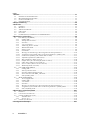
Inhalt
1 Preface.................................................................................................................................... 1-1
1.1
PURPOSE OF THE INFORMATION ................................................................................................ 1-1
1.2
REQUIRED BASIC KNOWLEDGE ................................................................................................. 1-1
1.3
SCOPE OF THIS MANUAL ........................................................................................................... 1-1
1.4
FURTHER SUPPORT .................................................................................................................... 1-1
2 Scope of Delivery .................................................................................................................. 2-2
3 Overview................................................................................................................................. 3-3
3.1
GENERAL .................................................................................................................................. 3-3
3.2
BENEFITS................................................................................................................................... 3-3
3.3
APPLICATION RANGE ................................................................................................................ 3-3
3.4
STRUCTURE ............................................................................................................................... 3-4
3.5
FUNCTION ................................................................................................................................. 3-4
3.6
COMMISSIONING AND SERVICE WITH SIWATOOL U ............................................................... 3-4
4 Description of the CFCs ....................................................................................................... 4-6
4.1
CFC SIWA_U08 (FB650) ........................................................................................................ 4-6
4.1.1
Calling OBs ...................................................................................................................... 4-6
4.1.2
Startup characteristics...................................................................................................... 4-6
4.1.3
Function............................................................................................................................ 4-6
4.1.4
User Text Library ............................................................................................................. 4-6
4.1.5
Addressing Driver wizzard ............................................................................................... 4-6
4.1.6
Manual/automatik............................................................................................................. 4-7
4.1.7
Data records..................................................................................................................... 4-8
4.1.8
Commands ........................................................................................................................ 4-9
4.1.9
Message text and message class assigned to the block parameters.................................4-10
4.1.10 Assignment of associated values to the block parameters of SIWA_U08 ........................4-11
4.1.11 Connections of SIWA_U08 (without data records) .........................................................4-11
4.1.12 Adjustment parameters (DR 3 and 4) ..............................................................................4-14
4.1.13 Base parameters (Data record 5) ....................................................................................4-20
4.1.14 Output values for remote display (Data record 6)...........................................................4-20
4.1.15 Limit values (Data record 21 and 22) .............................................................................4-21
4.1.16 Process values (Data records 31 and 32)........................................................................4-23
4.1.17 Modul info (data record 40) ............................................................................................4-25
4.2
CFC CMD_SU08 (FB651) ......................................................................................................4-26
4.2.1
Calling OBs .....................................................................................................................4-26
4.2.2
Start-up characteristics ...................................................................................................4-26
4.2.3
Function and functional principle ...................................................................................4-26
4.2.4
Interconnection with SIWA_U08 block............................................................................4-27
4.2.5
I/Os of CMD_SU08 .........................................................................................................4-27
4.3
MOD_SU08 (FB662) ..............................................................................................................4-28
4.3.1
Area of application ..........................................................................................................4-28
4.3.2
Calling OBs .....................................................................................................................4-28
4.3.3
Use in CFC ......................................................................................................................4-28
4.3.4
Function...........................................................................................................................4-28
4.3.5
Message text and message class assigned to the block parameters.................................4-29
4.3.6
Assignment of associated values to the block parameters of MOD_SIWA ......................4-29
4.3.7
I/Os von MOD_SU08.......................................................................................................4-29
5 Description of the Faceplates ............................................................................................5-31
5.1
GENERAL .................................................................................................................................5-31
5.2
CALLING UP FACEPLATES ........................................................................................................5-31
5.3
FACEPLATE DISPLAY IN OS......................................................................................................5-32
5.3.1
Standard View .................................................................................................................5-33
5.3.2
Service view .....................................................................................................................5-33
5.4
FACEPLATE CREATION..............................................................................................................5-35
6 Configuration Example .......................................................................................................6-37
iv
SIWAREX U
Preface
7 Abbreviations....................................................................................................................... 7-38
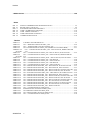
Bilder
FIG. 3-1
FIG. 4-1
FIG 5-1
FIG. 5-2
FIG. 5-3
FIG. 5-4
FIG. 5-5
INITIAL COMMISSIONING WITH SIWATOOL U ......................................................... 3-5
BLOCK SIWA_U08 IN CFC............................................................................................... 4-8
STANDARD VIEW FOR SIWAREX U ............................................................................5-33
VIEW CALIBRATION CHANNEL1.................................................................................5-34
VIEW LIMITS CHANNEL 1 ............................................................................................5-34
VIEW OPERATION CHANNEL 1 ....................................................................................5-35
COMMAND SELECTION .................................................................................................5-36
Tabellen
TABLE 1-1
TABLE 4-1
TABLE 4-2
TABLE 4-3
TABELLE 4-4
SCALED
TABLE 4-5
TABLE 4-6
SCALED
TABLE 4-7
TABLE 4-8
TABLE 4-9
TABLE 4-10
TABLE 4-11
TABLE 4-12
TABLE 4-13
TABLE 4-14
TABLE 4-15
TABLE 4-16
TABLE 4-17
TABLE 4-18
TABLE 4-19
TABLE 4-20
TABLE 4-21
TABLE 4-22
TABLE 4-23
TABLE 4-24
TABLE 4-25
TABLE 4-26
TABLE 4-27
TABLE 4-28
TABLE 4-29
VALIDITY OF THIS MANUAL................................................................................. 1-1
CFC – MESSAGE TEXTS OF SIWA_U08................................................................4-10
CFC – ASSOCIATED VALUES OF SIWA_U08 ......................................................4-11
CFC-CONNECTIONS OF SIWA_U08 (WITHOUT DATA RECORDS).................4-13
CFC – CONNECTIONS OF SIWA_U08 – DS3 OUTPUTS, DERIVATED OR
4-16
CFC – CONNECTIONS OF SIWA_U08– DS3 OUTPUTS, NOT SCALED ............4-16
CFC – CONNECTIONS OF SIWA_U08 – DS4 OUTPUTS, DERIVATED OR
4-19
CFC – CONNECTIONS OF SIWA_SU08 – DS4 OUTPUTS, NOT SCALED.........4-19
CFC – CONNECTIONS OF SIWA_U08 – DS5 INPUTS..........................................4-20
CFC – CONNECTIONS OF SIWA_U08 – DS5 OUTPUTS......................................4-20
CFC – CONNECTIONS OF SIWA_U08 – DS6 INPUTS..........................................4-20
CFC – CONNECTIONS OF SIWA_U08 – DS6 OUTPUTS......................................4-20
CFC–CONNECTIONS OF SIWA_U08 – DS21 INPUTS, SCALED VALUES .......4-21
CFC–CONNECTIONS OF SIWA_U08 – DS21 INPUTS, NOT SCALED ...............4-21
CFC–CONNECTIONS OF SIWA_U08 – DS21 OUTPUTS, SCALED VALUES....4-21
CFC–CONNECTIONS OF SIWA_U08 – DS21 OUTPUTS, NOT SCALED ...........4-21
CFC–ACONNECTIONS OF SIWA_U08 – DS22 INPUTS, SCALED VALUES.....4-22
CFC–CONNECTIONS OF SIWA_U08 – DS22 INPUTS, NOT SCALED ...............4-22
CFC–CONNECTIONS OF SIWA_U08 – DS22 OUTPUTS, SCALED VALUES....4-22
CFC–CONNECTIONS OF SIWA_U08 – DS22 OUTPUTS, NOT SCALED ...........4-22
CFC–CONNECTIONS OF SIWA_U08 – DS31 OUTPUTS, SCALED VALUE......4-23
CFC–CONNECTIONS OF SIWA_U08 – D31 OUTPUTS, NOT SCALED .............4-24
CFC–CONNECTIONS OF SIWA_U08 – DS32 OUTPUT, SCALED VALUE ........4-24
CFC–CONNECTIONS OF SIWA_U08 – D32 OUTPUTS, NOT SCALED .............4-25
CFC–CONNECTIONS OF SIWA_U08 – DS40 OUTPUTS......................................4-25
CFC – CONNECTIONS OF CMD_SU08 ..................................................................4-27
MAINTENANCE-STATES OF MOD_SU08.............................................................4-28
CFC MESSAGE TEXTS OF MOD_SU08 .................................................................4-29
CFC ASSOCIATED VALUES OF MOD_SU08........................................................4-29
CFC – CONNECTIONS OF MOD_SU08 ..................................................................4-30
SIWAREX U
v
1 Preface
1.1
Purpose of the Information
This manual contains all the information required to configure a plant using
SIWAREX U in PCS7.
1.2
Required Basic Knowledge
In order to understand the manual, certain knowledge concerning the SIMATIC
automation technology especially PCS7 is required. Weighing technology
knowledge is also an asset.
1.3
Scope of this Manual
This manual refers to the SIWAREX U module:
Type
Name
Order number
from product
status (Version)
SIWAREX U
SIWAREX U
7MH4950-1AA01
HW 1.0
FW 1.1
7MH4950-2AA01
Table 1-1
Validity of this manual
For these blocks PCS7 V7.0 from SP1 on is required.
1.4
Further Support
Do you have more questions concerning the use of SIWAREX U? Then please
contact your Siemens representative in the office or business location that is
responsible for your area or technical support for SIWAREX Tel.: +49 (0)721 595
2811.
Updated information on SIWAREX Weighing Technology as well as the newest
versions of the SIWAREX user manuals can be found on the respective Internet
Site.
http://www.siemens.com/weighing-technology
SIWAREX U
1-1
2 Scope of Delivery
The block is used to connect the SIWAREX U to the PCS7. The integration of
SIWAREX U is possible for PCS7 Version V7.0 as of SP1.
In the first step, SIWAREX U must be added to the hardware catalogue by running
the HSP.
While planning the hardware configuration in the SIMATIC Manager, the basic
features of the module are defined:
-
The peripheral address of the module
-
Enabling the diagnostic alarms
-
Enabling the process alarms
-
Behaviour in the case of a CPU-Stop
SIWAREX U takes up 16 bytes in the input and output area.
Other scale specific parameters that are also changed while the control program is
running can be defined in three different ways.
-
Using the SIWATOOL U parameter definition tool
- Internally by making the definition in FB650 and then transferring to
SIWAREX U
-
In the OS using the Faceplate.
PCS7 blocks include the following components:
SIWAREX U
-
CFC blocks for scale functionality (SIWA_U08), command controlling
(CMD_SU08) and maintenance (MOD_SU08)
-
Text libraries for use with message texts
-
Example – faceplate: can be extended or modified using the Faceplate
Designer.
-
Example program
2-2
Overview
3 Overview
3.1
General
SIWAREX U (Compact Scale) is a versatile and flexible weighing module, which
can be used wherever static scales are to be used in the SIMATIC S7 automation
system or a force measurement is necessary.
PCS7 blocks enable SIWAREX U to be integrated into PCS7. The faceplates
provided enable operation and monitoring of the scales and can be customized to
the client.
3.2
Benefits
SIWAREX Getting Started has many advantages:
3.3
o
Easy integration of scales in PCS7
o
Straightforward transmission of commands in automatic mode
o
Integration with PCS7 Maintenance Station
o
Completed faceplates available for project-specific enhancements
Application Range
SIWAREX U is the optimal solution wherever the aim is to detect signals from
strain gauge sensors or load cells. As weighing electronics, SIWAREX U offers
good accuracy with a measuring time of 20 ms.
SIWAREX U is optimally equipped for the following applications:
o
The fill-level monitoring of silos and bunkers
o
The measurement of crane and rope loads, other strength measurements
o
Load measurement for industrial elevators or rolling mills
o
Weighing in areas with a risk of explosion (with SIWAREX IS Ex interface)
o
Belt tensioning measurement
SIWAREX U
3-3
3.4
Structure
The project is made up of two parts:
-
SIWAREX U PCS7 AS blocks
-
SIWAREX U PCS7 OS blocks
The ALARM_8P messaging system is also used. In this way, the messages from
SIWAREX U are displayed to the operator. The message texts are stored in the
text library provided.
3.5
Function
The primary task of SIWAREX U consists in the measurement of the current weight
value. By means of the integration in SIMATIC, there is the option of processing
the weight value directly in the PLC.
SIWAREX-specific CFCs are available for configuration purposes. These are used
to transfer commands and setting values to the scales. The scales can be
operated, and the scale data displayed using the faceplates.
3.6
Commissioning and Service with SIWATOOL U
In principle, complete commissioning is possible via the CFC block.
Adjustment parameters (data record 3 and 4) can be modified retrospectively and
scales readjusted via the faceplates.
The limits of both channels (data record 21 and 22) can be entered via the
faceplate.
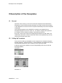
It is also possible to quickly and easily commission the module using the
SIWATOOL PC program.
SIWATOOL U is included in the scope of delivery of the SIWAREX U configuration
package for PCS7 (order number 7MH4950-3AK61). The program must be
installed on a PC before commissioning can be performed. The PC is connected to
the SIWAREX U using the cable available as an accessory.
3-4
SIWAREX U
Overview
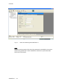
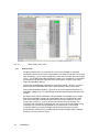
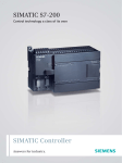
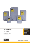
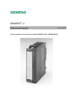
Fig. 3-1
Initial commissioning with SIWATOOL U
Note:
All data should be read by PCS7 after the parameters for SIWAREX U have been
defined using SIWATOOL. Data in SIWAREX U will then be synchronized with
data in the PCS7 project.
SIWAREX U
3-5
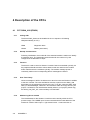
4 Description of the CFCs
4.1
4.1.1
CFC SIWA_U08 (FB650)
Calling OBs
The block SIWA_U08 must be installed in the run sequence of following
OBs(automatically in CFC):
4.1.2
OB82
Diagnostic alarm
OB100
Restart (warm start)
Startup characteristics
Following initialization, the module ID of the attached module is read out to identify
a parameter error. The messages remain blocked for the number of cycles
configured at the RUNUPCYC input.
4.1.3
Function
The block is used to control a Siwarex U module. Data is transmitted cyclically via
the peripheral interface and the various data records are read from the module
and/or transferred to the module acyclically. The module message queue is
continually read out and corresponding WinCC messages are issued.
4.1.4
User Text Library
Various messages in WinCC include an error text from user text libraries in addition
to the error number. The user text libraries must be copied from the SIWA_U08
block library to the respective project by the user. To do this, open the SIWA_U08
library in SimaticManager, select the "Text Libraries" folder and copy this into your
project. If a folder for user text libraries already exists in your project, please copy
the SIWA_U08_DAT_OP, user text library into this folder.
4.1.5
Addressing Driver wizzard
The IO addresses for the Siwarex U module must be entirely within the CPU
process-image. The LADDR input is interconnected with the base address of the
Siwarex U module: Select input -> right mouse button -> Interconnection to
4-6
SIWAREX U
Description of the CFCs
Address... -> input from e.g. IW512. The PCS7 driver wizard then automatically
installs all required driver blocks. The MODF, PERAF, RACKF , ODIAG, ENCO
and EN_CO block parameters are interconnected by the driver wizard; the
SUBN1_ID, SUBN2_ID, RACK_NO, SLOT_NO, BASADR, DADDR and CO_NO
inputs are configured according to the data from HW config.
4.1.6
Manual/automatik
Switching between the two modes of operation is carried out either through OS
operation via AUT_ON_OP (LIOP_SEL = 0) or via the interconnection of the
AUT_L (LIOP_SEL = 1) input. The appropriate permissions AUTOP_EN and
MANOP_EN are required if the OS system route is taken. The operating mode
selected is displayed on the QMAN_AUT output (1: automatic, 0: manual).
Manual Mode: Commands are transmitted from the operator to the block via the
MAN_CMD input. Every command code modification on this input is identified as a
new command. Manual inputs (ending "_M") act as the source for data records
transmitted to the module.
Automatic mode: The block obtains its commands, with positive edge, at the
AUTCMDEN input, from the AUT_CMD connectable input. Automatic inputs
(ending "_A"), if available, act as the source for data records transmitted to the
module; if unavailable, manual inputs fulfil this role (ending "_M").
Instead of the error code and a positive edge, automatic commands can also be
triggered with the help of a connection block (see chapter 4.2) by adjusting a bit.
If no automatic command is being processed, but a command is nevertheless
present at the MAN_CMD manual input, then this is executed, but always with the
manual inputs (ending "_M") as the source for data records written to the module.
If neither a manual nor an automatic command is executed, then the background
command specified at the BACK_CMD input is executed cyclically.
A command chain (e.g. read all data records) is interrupted by a new error code,
but only ever after the individual command currently being processed has been
executed.
SIWAREX U
4-7
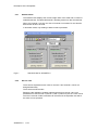
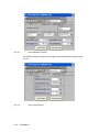
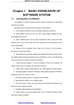
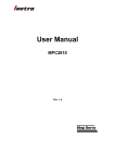
Fig. 4-1
4.1.7
Block SIWA_U08 in CFC
Data records
All data records that the S7 controller can access are available as individual
parameters for the function block. Parameters for the data records that can be read
take the ending "_O" for Output. Parameters of the data records that can be written
end in "_M" for Manual and are transferred to WinCC for visualization. If applicable,
manual inputs can also be connected in the AS program; however, they will no
longer be operable in WinCC.
Values from SIWAREX are assumed for parameters ending "_M" and "_O" when
data records from SIWAREX are read, in both automatic and manual modes.
The manual parameters (ending "_M") acts as the source datasets are written in
SIWAREX. Dataset 3 or 4 is automatically read back after being transferred to the
module.
All weight values from the dataset are also available as Real data input or output.
Before every dataset is written, the scaled REAL value is converted into a fixed
point value using the parameterized decimal places of the respective channel
(output DEC_PLACE_x_O); this value is then transferred to the module. The
unscaled input must not be changed by the user, as this will be overwritten during
conversion. All unscaled input is labeled as "for internal use" in the module
comments. Before you input the weight values the decimal places must be
parameterized. Otherwise it is possible that the unscaled weight value is falsified
because of a wrong number format.
4-8
SIWAREX U
Description of the CFCs
After a dataset with scaled values has been read, its fixed point values are also
converted and made available as REAL values. Unscaled outputs are labeled with
"NC" ("not scaled") in the parameter names and can be further connected.
In SIWAREX U, some of the weighing specific data (e.g. number of decimal
places) in datasets 3 and 4 is coded in bit groups. In CFC, the individual bits of
these groups are merged into a byte and are made available as input or output on
the module interface. Similarly to the scaling of weight values, these values are
coded and decoded after the corresponding datasets are read or before the
datasets are written. The numerical values of these inputs/outputs are transcoded
into the relevant weighing-specific data.
4.1.8
Commands
Block command inputs in automatic mode are processed with the following
priorities:
1. Automatic command (AUT_CMD, AUTCMDEN), automatic operating mode
required
2. Manual command (MAN_CMD)
3. Command from adding a faceplate view (FP_CMD)
4. Background command (BACK_CMD)
If a new view is added in the faceplate, then the data records are read out whose
values are presented here. The command code required for this is written to the
FP_CMD parameter and copied to the MAN_CMD input (manual command) via the
block and is thus executed as a manual command, assuming no other command is
present here.
Code
Channel 1
1
Code Channel
2
101
2
102
3
103
5
105
Command explanation
Adjustment command adjustment zero valid
Adjustment zero command valid (activates calibration mode)
The start of the characteristic curve - adjustment zero of the
scale - is defined with the momentary dead-load.
Adjustment command - adjustment weight 1 valid
The first adjustment point is determined by the momentary
weight of the positioned adjustment weight.
Set scale to zero
The current weight is set to zero.
Predefine all data records with default values
All parameters are set to the status that was assigned originally
by the manufacturer. The command always works on both
channels.
The reading of a dataset is initiated using the command code "200 + dataset
number"; the writing is initiated using "400 + dataset number". Furthermore, there
are the following linked commands:
Code
601
602
604
SIWAREX U
Command explanation
Read all datarecords of channel 1: DR 3, 5, 6, 21, 31 und 40
Read all datarecords of channel 2: DR 4, 5, 6, 22, 32 und 40
Read DR 3 und 4
4-9
605
606
607
610
Read all datarecords: DR 3, 4, 5, 6, 21, 22, 31, 32 und 40
Write all datarecords of channel 1: DR 3, 5, 6 und 21
Write all datarecords of channel 2: DR 4, 5, 6 und 22
Write all datarecords: DR 3, 4, 5, 6, 21 und 22
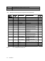
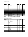
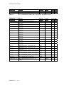
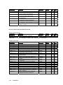
4.1.9
Message text and message class assigned to the block parameters
Messageblock
ALARM_8P
EV_ID1
EV_ID2
EV_ID3
Table 4-1
4-10
Block parameter
Default message text
Messageclass
1
2
3
4
5
6
7
8
1
2
3
QPARF
CSF/QCSF
QE_RAM
QE_WDOG
QE_PALM
QE_EEPROM
QE_ADC
QE_EPROM
QCH1_FLT
QCH2_FLT
QE_MINV1
S
S
S
S
S
S
S
S
S
S
S
4
QE_MINV2
5
QE_OFL1
6
QE_OFL2
7
QE_MEAS1
8
QE_MEAS2
1
2
QE_EXTV
(interne Variable)
3
(interne Variable)
Parametrierfehler
Externer Fehler (Leittechnik)
RAM Fehler Schreib-Leseprüfung
Watchdogfehler
Prozessalarm verloren
EEPROM-Fehler
ADU-Fehler
EPROM-Fehler
Kanal 1 gestört
Kanal 2 gestört
Kanal1: Mindestspn. an
Senseleitungen unterschritten
Kanal2: Mindestspn. an
Senseleitungen unterschritten
Kanal1: Zahlenüberlauf bei
Bruttogewicht
Kanal2: Zahlenüberlauf bei
Bruttogewicht
Kanal1:
Messbereichsüberschreitung
Kanal2:
Messbereichsüberschreitung
Externe Hilfsspannung fehlt
Daten/Bedienfehler Kanal1
(@8%d@):
@8Y%t#SIWA_U08_DAT_OP@
Daten/Bedienfehler Kanal2
(@9%d@):
@9Y%t#SIWA_U08_DAT_OP@
4
5
6
7
8
SIG3_4
SIG3_5
SIG3_6
SIG3_7
SIG3_8
MessageNo.
CFC – Message texts of SIWA_U08
SIWAREX U
S
S
S
S
S
S
S
S
Description of the CFCs
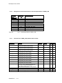
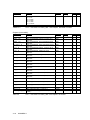
4.1.10
Assignment of associated values to the block parameters of SIWA_U08
Messageno.
Messageblock
ALARM_8P
EV_ID1
Table 4-2
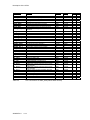
4.1.11
1
2
3
4
5
6
7
8
9
10
Block parameter
BA_NA
STEP_NO
BA_ID
SUBN1_ID
SUBN2_ID
RACK_NO
SLOT_NO
si_NO_DAT_OP_CH1
si_NO_DAT_OP_CH2
AUX2PR10
CFC – Associated values of SIWA_U08
Connections of SIWA_U08 (without data records)
Connection
(Parameter)
MODF
PERAF
RACKF
SUBN1_ID
SUBN2_ID
RACK_NO
SLOT_NO
BASADR
DADDR
LADDR
MANOP_EN
AUTOP_EN
LIOP_SEL
SIWAREX U
Meaning
Data type
1=Module failure
(is interconnected by module driver)
1=Peripherie access failure
(is interconnected by module driver)
1=Rack failure
(is interconnected by module driver)
ID of Primary Subnet
(configured by the driver wizard)
ID of Redundant Subnet
(configured by the driver wizard)
Rack Number
(configured by the driver wizard)
Slot Number
(configured by the driver wizard)
Base Address of Siwarex-U Module
(configured by the driver wizard)
Diagnostic Address of Siwarex-U Module
(configured by the driver wizard)
Base Address of Siwarex-U Module
This input must be interconnected to the
base address: Right mouse button ->
Interconnection to Address... -> e.g. IW128
Enable: 1=Operator may input MANUAL
Enable: 1=Operator may input AUTO
Select: 1=Linking, 0=Operator active
4-11
Type O&O
BOOL
Default
setting
FALSE
BOOL
FALSE
I
BOOL
FALSE
I
BYTE
16#FF
I
BYTE
16#FF
I
BYTE
0
I
BYTE
0
I
INT
0
I
INT
0
I
WORD
0
I
BOOL
BOOL
BOOL
TRUE
TRUE
FALSE
I
I
I
I
Connection
(Parameter)
AUT_L
MSG_LOCK
RUNUPCYC
EV_ID1
EV_ID2
EV_ID3
BA_EN
OCCUPIED
BA_ID
BA_NA
STEP_NO
BACK_CMD
AUT_CMD
AUTCMDEN
SIG3_x
4 <= x <= 8
CO_NO
AUX2PR10
AUT_ON_OP
MAN_CMD
FP_CMD
CH_EXIST
CH_OK
EN_CO
CPU_DIAG
QCSF
QPARF
QMODF
QPERAF
QRACKF
QCH1_FLT
QCH2_FLT
QCH2_NEX
ODIAG
SFB_ERR_C
L_DR_NO
L_CMD
QMAN_AUT
QMANOP
QAUTOP
QCMDOP
M_CMD_EN
QMSG_SUP
QMSGERR1
QMSGERR2
QMSGERR3
MSG_STAT1
MSG_STAT2
MSG_STAT3
MSG_ACK1
MSG_ACK2
MSG_ACK3
CMD_INPR
CMD_FOK
CMD_ERR
4-12
Meaning
Data type
Linkable Input for MANUAL/AUTO mode
Message Lock
Lag: Number of Run Up Cycles
Message ID1
Message ID2
Message ID3
Batch Enable
Occupied by Batch
Batch ID
Batch Name
Batch Step Number
Background Command
Auto Command
Execute command in Automatic Mode
free Message EV_ID3/Message x
BOOL
BOOL
INT
DWORD
DWORD
DWORD
BOOL
BOOL
DWORD
STRING[32]
DWORD
INT
INT
BOOL
BOOL
Coordination Number
Auxiliary Value 10/ EV_ID2
Operator Input Mode 1=AUTO, 0=MANUAL
Manual Command
Faceplate Command
Channel exist
Channel OK
Coordination Number
CPU diagnosis (system structure)
1=Control System Fault
1=Parametration failure
1=Module failure
1=Peripherie access failure
1=Rack failure
Channel 1 fault
Channel 2 fault
1 = Channel 2 does not exist
Diagnostic Info
Error code of last SFB call
Data record of the last started transfer
Last transferred Command
1=AUTO, 0=MANUAL Mode
Status: 1=Operator enabled for MANUAL
Status: 1=Operator enabled for AUTO
1=Operator may start a command
Enable: 1=Operator may input new
MAN_CMD
1=Message Suppression Active
1=Message ERROR 1
1=Message ERROR 2
1=Message ERROR 3
Message: STATUS Output 1
Message: STATUS Output 2
Message: STATUS Output 3
Message: ACK_STATE Output 1
Message: ACK_STATE Output 2
Message: ACK_STATE Output 3
Automatic command in progress
Automatic command finished ok
Error by automatic command execution
INT
ANY
BOOL
INT
INT
DWORD
DWORD
STRUCT
STRUCT
BOOL
BOOL
BOOL
BOOL
BOOL
BOOL
BOOL
BOOL
DWORD
WORD
INT
INT
BOOL
BOOL
BOOL
BOOL
BOOL
FALSE
FALSE
FALSE
FALSE
FALSE
FALSE
FALSE
FALSE
0
0
0
0
FALSE
FALSE
FALSE
FALSE
TRUE
I
IO
IO
IO
IO
IO
IO
IO
IO
O
O
O
O
O
O
O
O
O
O
O
O
O
O
O
O
O
BOOL
BOOL
BOOL
BOOL
WORD
WORD
WORD
WORD
WORD
WORD
BOOL
BOOL
BOOL
FALSE
FALSE
FALSE
FALSE
0
0
0
0
0
0
FALSE
FALSE
FALSE
O
O
O
O
O
O
O
O
O
O
O
O
O
SIWAREX U
Default
setting
TRUE
FALSE
10
0
0
0
FALSE
FALSE
0
0
0
0
FALSE
FALSE
FALSE
0
0
0
0
Type O&O
I
I
I
I
I
I
I
I
I
I
I
I
I
I
I
x
x
x
x
x
x
x
x
x
x
x
x
x
x
x
x
x
x
Description of the CFCs
Connection
(Parameter)
CMD_ERR_C
MCMD_INPR
MCMD_FOK
MCMD_ERR
MCMD_ERR_C
BACK_INPR
BACK_FOK
BACK_ERR
BACK_ERR_C
REF_COUNT1
SC_STATUS1
ASYNC_ERR1
GROSS1
GROSS_NC_1
FLT_RAW1
REF_COUNT2
SC_STATUS2
ASYNC_ERR2
GROSS2
GROSS_NC_2
FLT_RAW2
FB_ERR
FB_ERR_C
START_UP
QE_RAM
QE_WDOG
QE_PALM
QE_EEPROM
QE_ADC
QE_EPROM
QE_MINV1
QE_MINV2
QE_OFL1
QE_OFL2
QE_MEAS1
QE_MEAS2
QE_EXTV
ENCO
Table 4-3
SIWAREX U
Meaning
Data type
Type O&O
BYTE
BOOL
BOOL
BOOL
BYTE
BOOL
BOOL
BOOL
BYTE
Default
setting
16#00
FALSE
FALSE
FALSE
16#00
FALSE
FALSE
FALSE
0
Error code for automatic command execution
Manual command in progress
Manual command finished ok
Error by manual command execution
Error code for manual command execution
Background command in progress
Background command finished ok
Error by background command execution
Error code for background command
execution
Refresh counter channel 1
Status of the scale channel 1
Asynchronous error channel 1
Gross value channel 1
Gross value channel 1 (not scaled)
Filtered raw value channel 1
Refresh counter channel 2
Status of the scale channel 2
Asynchronous error channel 2
Gross value channel 2
Gross value channel 2 (not scaled)
Filtered raw value channel 2
Function block error occurred
Function block error code
Start up of Siwarex in progress
1=RAM Error
1=Watchdog Error
1=Process Alarm lost
1=EEPROM Error
1=Analog/Digital Converter Error
1=EPROM Error
1=Minimum voltage undershot at the sense
lines channel1
1=Minimum voltage undershot at the sense
lines channel2
1=Gross weight number overflow channel1
1=Gross weight number overflow channel2
1=Measuring range exceeded channel1
1=Measuring range exceeded channel2
1=External auxiliary voltage missing
Enable Coordination Number
BYTE
BYTE
WORD
REAL
INT
WORD
BYTE
BYTE
WORD
REAL
INT
WORD
BOOL
BYTE
BOOL
BOOL
BOOL
BOOL
BOOL
BOOL
BOOL
BOOL
16#00
16#00
16#00
0.0
0
16#00
16#00
16#00
16#00
0.0
0
16#00
FALSE
16#00
FALSE
FALSE
FALSE
FALSE
FALSE
FALSE
FALSE
FALSE
O
O
O
O
O
O
O
O
O
O
O
O
O
O
O
O
O
O
O
O
O
O
BOOL
FALSE
O
BOOL
BOOL
BOOL
BOOL
BOOL
BYTE
FALSE
FALSE
FALSE
FALSE
FALSE
O
O
O
O
O
O
CFC-connections of SIWA_U08 (without data records)
4-13
O
O
O
O
O
O
O
O
O
x
x
x
x
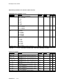
4.1.12
Adjustment parameters (DR 3 and 4)
Adjustment parameters for channel 1 (Data record 3):
Inputs (derivated or scaled values):
Connection
(Parameter)
WGH_UNIT_1_M
CHAR_V_1_M
DEC_PLACE_1_M
FLT_SET_1_M
AWGHT_1_M
Table 4-6
Meaning
Data type
DR3: Weight unit, Channel 1
0 = ' ' (no unit)
1 = 'g'
2 = 'kg'
3 = 't'
4 = 'oz'
5 = 'lb'
6 = 'lbs'
7 = 'kN'
DR3: Char. value of the load cell, Channel 1
0 = '<= 1mV/V'
1 = '<= 2mV/V'
2 = '<= 4mV/V'
DR3: Decimal place for remote display,
Channel 1
0 = 'XXXXX'
1 = 'XXXX.X'
2 = 'XXX.XX'
3 = 'XX.XXX'
4 = 'X.XXXX'
DR3: Filter setting, Channel 1
0 = '---'
1 = '5Hz'
2 = '2Hz'
3 = '1Hz'
4 = '0.5Hz'
5 = '0.2Hz'
6 = '0.1Hz'
7 = '0.05Hz'
DR3: Adjustment weight, Channel 1
BYTE
I
x
BYTE
I
x
BYTE
I
x
BYTE
I
x
I
x
REAL
Default
setting
10000.0
Type O&O
CFC – connections of SIWA_U08 – DS3 inputs, derivated or scaled
Inputs (not scaled):
Connection
(Parameter)
Z_SET_1_M
AVGF_1_M
SEEP_1_M
CH_ACT_1_M
B11_1_M
B12_1_M
B13_1_M
4-14
Meaning
Data type
DR3: Zero setting value, Channel 1
WORD
BOOL
I
I
x
x
BOOL
I
x
BOOL
I
x
BOOL
I
x
BOOL
I
BOOL
I
DR3: Adj parameter average val. filter, bit 8,
Channel 1
DR3: Adj parameter, save in EEPROM, bit 9,
Channel 1
DR3: Adj parameter, channel activated, bit 10,
Channel 1
DR3: Adj parameter settings, reserved, bit 11,
Channel 1
DR3: for internal use, Adj parameter, weight
unit, bit 0, Channel 1
DR3: for internal use, Adj parameter, weight
unit, bit 1, Channel 1
SIWAREX U
Default
setting
Type O&O
Description of the CFCs
Connection
(Parameter)
B14_1_M
B15_1_M
B0_1_M
B1_1_M
B2_1_M
B3_1_M
B4_1_M
B5_1_M
B6_1_M
B7_1_M
DIG0_1_M
DIG1_1_M
INTERN_1_M
Table 4-6
Meaning
Data type
DR3: for internal use, Adj parameter, weight
unit, bit 2, Channel 1
DR3: Adj parameter, reserved, bit 15,
Channel 1
DR3: for internal use, Adj parameter, char.
value, bit 0, Channel 1
DR3: for internal use, Adj parameter, char.
value, bit 1, Channel 1
DR3: for internal use, bit 0 of Char. value of
the load cell, Channel 2
DR3: for internal use, bit 1 of Char. value of
the load cell, Channel 2
DR3: for internal use, bit 2 of Char. value of
the load cell, Channel 2
DR3: for internal use, Adj parameter, limit
freq., bit 0, Channel
DR3: for internal use, Adj parameter, limit
freq., bit 1, Channel 1
DR3: for internal use, Adj parameter, limit
freq., bit 2, Channel 1
DR3: Adjustment digit 0, Channel 1
DR3: Adjustment digit 1, Channel 1
DR3: for internal use, Adjustment weight,
Channel 1 (not scaled)
BOOL
I
BOOL
I
BOOL
I
BOOL
I
BOOL
I
BOOL
I
BOOL
I
BOOL
I
BOOL
I
BOOL
I
WORD
WORD
INT
I
I
I
Default
setting
10000
Type O&O
x
x
x
x
CFC – connections of SIWA_U08 – DS3 inputs, not scaled
Outputs (derivated or scaled values):
Connection
(Parameter)
WGH_UNIT_1_O
Meaning
WGH_UNIT_B_1
_O
CHAR_V_1_O
DEC_PLACE_1_
O
FLT_SET_1_O
SIWAREX U
4-15
DR3: Weight unit, Channel 1
DR3: Weight unit (Byte), Channel 1
0 = ' ' (keine Einheit)
1 = 'g'
2 = 'kg'
3 = 't'
4 = 'oz'
5 = 'lb'
6 = 'lbs'
7 = 'kN'
DR3: Char. value of the load cell, Channel 1
0 = '<= 1mV/V'
1 = '<= 2mV/V'
2 = '<= 4mV/V'
DR3: Decimal place for remote display,
Channel 1
0 = 'XXXXX'
1 = 'XXXX.X'
2 = 'XXX.XX'
3 = 'XX.XXX'
4 = 'X.XXXX'
DR3: Filter setting, Channel 1
0 = '---'
1 = '5Hz'
Data type
Default
setting
Type O&O
STRING[3
]
BYTE
O
BYTE
O
BYTE
O
BYTE
O
O
X
Connection
(Parameter)
Meaning
2 = '2Hz'
3 = '1Hz'
4 = '0.5Hz'
5 = '0.2Hz'
6 = '0.1Hz'
7 = '0.05Hz'
DR3: Adjustment weight, Channel 1
AWGHT_1_O
Tabelle 4-4
Data type
REAL
Default
setting
10000.0
Type O&O
O
CFC – connections of SIWA_U08 – DS3 outputs, derivated or scaled
Outputs (not scaled):
Connection
(Parameter)
Z_SET_1_O
AVGF_1_O
SEEP_1_O
CH_ACT_1_O
B11_1_O
B12_1_O
B13_1_O
B14_1_O
B15_1_O
B0_1_O
B1_1_O
B2_1_O
B3_1_O
B4_1_O
B5_1_O
B6_1_O
B7_1_O
DIG0_1_O
DIG1_1_O
AWGHT_NC_1_O
Table 4-5
4-16
Meaning
Data type
DR3: Zero setting value, Channel 1
DR3: Adj parameter average val. filter, bit 8,
Channel 1
DR3: Adj parameter, save in EEPROM, bit 9,
Channel 1
DR3: Adj parameter, channel activated, bit 10,
Channel 1
DR3: Adj parameter settings, reserved, bit 11,
Channel 1
DR3: Adj parameter, weight unit, bit 0,
Channel 1
DR3: Adj parameter, weight unit, bit 1,
Channel 1
DR3: Adj parameter, weight unit, bit 2,
Channel 1
DR3: Adj parameter, reserved, bit 15,
Channel 1
DR3: Adj parameter, char. value, bit 0,
Channel 1
DR3: Adj parameter, char value, bit 1,
Channel 1
DR3: Adj parameter, decimal point, bit 0,
Channel 1
DR3: Adj parameter, decimal point, bit 1,
Channel 1
DR3: Adj parameter, decimal point, bit 2,
Channel 1
DR3: Adj parameter, limit freq., bit 0, Channel
1
DR3: Adj parameter, limit freq., bit 1, Channel
1
DR3: Adj parameter, limit freq., bit 2, Channel
1
DR3: Adjustment digit 0, Channel 1
DR3: Adjustment digit 1, Channel 1
DR3: Adjustment weight, Channel 1 (not
scaled)
WORD
BOOL
O
O
BOOL
O
BOOL
O
BOOL
O
BOOL
O
BOOL
O
BOOL
O
BOOL
O
BOOL
O
BOOL
O
BOOL
O
BOOL
O
BOOL
O
BOOL
O
BOOL
O
BOOL
O
WORD
WORD
INT
O
O
O
Default
setting
10000
CFC – connections of SIWA_U08– DS3 outputs, not scaled
SIWAREX U
Type O&O
Description of the CFCs
Adjustment parameters for channel 2 (Data record 4):
Inputs (derivated or scaled values):
Meaning
Connection
(Parameter)
WGH_UNIT_2_M
DR4: Weight unit, Channel 2
0 = ' ' (no unit)
1 = 'g'
2 = 'kg'
3 = 't'
4 = 'oz'
5 = 'lb'
6 = 'lbs'
7 = 'kN'
CHAR_V_2_M
DR4: Char. value of the load cell, Channel 2
0 = '<= 1mV/V'
1 = '<= 2mV/V'
2 = '<= 4mV/V'
DEC_PLACE_2_
DR4: Decimal place for remote display,
M
Channel 2
0 = 'XXXXX'
1 = 'XXXX.X'
2 = 'XXX.XX'
3 = 'XX.XXX'
4 = 'X.XXXX'
FLT_SET_2_M
DR4: Filter setting, Channel 2
0 = '---'
1 = '5Hz'
2 = '2Hz'
3 = '1Hz'
4 = '0.5Hz'
5 = '0.2Hz'
6 = '0.1Hz'
7 = '0.05Hz'
AWGHT_2_M
DR4: Adjustment weight, Channel 2
Table 4-6
Data type
Default
setting
Type O&O
BYTE
I
X
BYTE
I
X
BYTE
I
X
BYTE
I
X
I
X
REAL
10000.0
CFC – connections of SIWA_U08 – DS4 inputs, derivated or scaled
Inputs (not scaled):
Connection
(Parameter)
Z_SET_2_M
AVGF_2_M
SEEP_2_M
CH_ACT_2_M
B11_2_M
B12_2_M
B13_2_M
B14_2_M
B15_2_M
SIWAREX U
Meaning
Data type
DR4: Zero setting value, Channel 2
DR4: Adj parameter average val. filter, bit 8,
Channel 2
DR4: Adj parameter, save in EEPROM, bit 9,
Channel 2
DR4: Adj parameter, channel activated, bit 10,
Channel 2
DR4: Adj parameter settings, reserved, bit 11,
Channel 2
DR4: for internal use, Adj parameter, weight
unit, bit 0, Channel 2
DR4: for internal use, Adj parameter, weight
unit, bit 1, Channel 2
DR4: for internal use, Adj parameter, weight
unit, bit 2, Channel 2
DR4: Adj parameter, reserved, bit 15,
WORD
BOOL
I
I
X
X
BOOL
I
X
BOOL
I
X
BOOL
I
X
BOOL
I
BOOL
I
BOOL
I
BOOL
I
4-17
Default
setting
Type O&O
X
Connection
(Parameter)
B0_2_M
B1_2_M
B2_2_M
B3_2_M
B4_2_M
B5_2_M
B6_2_M
B7_2_M
DIG0_2_M
DIG1_2_M
INTERN_2_M
Table 4-6
Meaning
Channel 2
DR4: for internal use, Adj parameter, char.
value, bit 0, Channel 2
DR4: for internal use, Adj parameter, char.
value, bit 1, Channel 2
DR4: for internal use, Adj parameter, decimal
point, bit 0, Channel 2
DR4: for internal use, Adj parameter, decimal
point, bit 1, Channel 2
DR4: for internal use, Adj parameter, decimal
point, bit 2, Channel 2
DR4: for internal use, Adj parameter, limit
freq., bit 0, Channel 2
DR4: for internal use, Adj parameter, limit
freq., bit 1, Channel 2
DR4: for internal use, Adj parameter, limit
freq., bit 2, Channel 2
DR4: Adjustment digit 0, Channel 2
DR4: Adjustment digit 1, Channel 2
DR4: for internal use, Adjustment weight,
Channel 2 (not scaled)
Data type
Default
setting
Type O&O
BOOL
I
BOOL
I
BOOL
I
BOOL
I
BOOL
I
BOOL
I
BOOL
I
BOOL
I
WORD
WORD
INT
I
I
I
10000
X
X
X
CFC – connections of SIWA_U08 – DS4 inputs, not scaled
Outputs (derivated or scaled values):
Connection
(Parameter)
WGH_UNIT_2_O
WGH_UNIT_B_2_
O
CHAR_V_2_O
DEC_PLACE_2_O
FLT_SET_2_O
4-18
Meaning
Data type
DR4: Weight unit, Channel 2
DR4: Weight unit (Byte), Channel 2
0 = ' ' (keine Einheit)
1 = 'g'
2 = 'kg'
3 = 't'
4 = 'oz'
5 = 'lb'
6 = 'lbs'
7 = 'kN'
DR4: Char. value of the load cell, Channel 2
0 = '<= 1mV/V'
1 = '<= 2mV/V'
2 = '<= 4mV/V'
DR4: Decimal place for remote display,
Channel 2
0 = 'XXXXX'
1 = 'XXXX.X'
2 = 'XXX.XX'
3 = 'XX.XXX'
4 = 'X.XXXX'
DR4: Filter setting, Channel 2
0 = '---'
1 = '5Hz'
2 = '2Hz'
3 = '1Hz'
4 = '0.5Hz'
5 = '0.2Hz'
6 = '0.1Hz'
STRING[3]
BYTE
O
O
BYTE
O
BYTE
O
BYTE
O
SIWAREX U
Default
setting
Type O&O
X
Description of the CFCs
Connection
(Parameter)
AWGHT_2_O
Table 4-6
Meaning
Data type
Default
setting
Type O&O
7 = '0.05Hz'
DR4: Adjustment weight, Channel 2
REAL
10000.0
O
CFC – connections of SIWA_U08 – DS4 outputs, derivated or scaled
Outputs (not scaled):
Connection
(Parameter)
Z_SET_2_O
AVGF_2_O
SEEP_2_O
CH_ACT_2_O
B11_2_O
B12_2_O
B13_2_O
B14_2_O
B15_2_O
B0_2_O
B1_2_O
B2_2_O
B3_2_O
B4_2_O
B5_2_O
B6_2_O
B7_2_O
DIG0_2_O
DIG1_2_O
AWGHT_NC_2_O
Table 4-7
SIWAREX U
Meaning
Data type
Default
setting
DR4: Zero setting value, Channel 2
DR4: Adj parameter average val. filter, bit 8,
Channel 2
DR4: Adj parameter, save in EEPROM, bit 9,
Channel 2
DR4: Adj parameter, channel activated, bit 10,
Channel 2
DR4: Adj parameter settings, reserved, bit 11,
Channel 2
DR4: Adj parameter, weight unit, bit 0,
Channel 2
DR4: Adj parameter, weight unit, bit 1,
Channel 2
DR4: Adj parameter, weight unit, bit 2,
Channel 2
DR4: Adj parameter, reserved, bit 15,
Channel 2
DR4: Adj parameter, char. value, bit 0,
Channel 2
DR4: Adj parameter, char value, bit 1,
Channel 2
DR4: Adj parameter, decimal point, bit 0,
Channel 2
DR4: Adj parameter, decimal point, bit 1,
Channel 2
DR4: Adj parameter, decimal point, bit 2,
Channel 2
DR4: Adj parameter, limit freq., bit 0, Channel
2
DR4: Adj parameter, limit freq., bit 1, Channel
2
DR4: Adj parameter, limit freq., bit 2, Channel
2
DR4: Adjustment digit 0, Channel 2
DR4: Adjustment digit 1, Channel 2
DR4: Adjustment weight, Channel 2 (not
scaled)
WORD
BOOL
O
O
BOOL
O
BOOL
O
BOOL
O
BOOL
O
BOOL
O
BOOL
O
BOOL
O
BOOL
O
BOOL
O
BOOL
O
BOOL
O
BOOL
O
BOOL
O
BOOL
O
BOOL
O
WORD
WORD
INT
O
O
O
10000
CFC – connections of SIWA_SU08 – DS4 outputs, not scaled
4-19
Type O&O
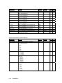
4.1.13
Base parameters (Data record 5)
Inputs:
Connection
(Parameter)
MOD_N_M
P_BIT_M
P_TYPE_M
T_RDISP_M
A_LED_1_M
A_LED_2_M
Res15_M
Table 4-8
Meaning
DR5: Module number
DR5: With or without parity bit
DR5: Even parity / Odd parity
DR5: Type of remote display
DR5: Allocation of LED 1
DR5: Allocation of LED 2
DR5: Reserved
Data type
BYTE
BOOL
BOOL
BYTE
BYTE
BYTE
BYTE
Default
setting
B#16#65
B#16#66
Type O&O
I
I
I
I
I
I
I
X
X
X
X
X
X
X
CFC – connections of SIWA_U08 – DS5 inputs
Outputs:
Connection
(Parameter)
MOD_N_O
P_BIT_O
P_TYPE_O
T_RDISP_O
A_LED_1_O
A_LED_2_O
Res15_O
Table 4-9
4.1.14
Meaning
DR5: Module number
DR5: With or without parity bit
DR5: Even parity / Odd parity
DR5: Type of remote display
DR5: Allocation of LED 1
DR5: Allocation of LED 2
DR5: Reserved
Data type
BYTE
BOOL
BOOL
BYTE
BYTE
BYTE
BYTE
Default
setting
Type O&O
O
O
O
O
O
O
O
B#16#65
B#16#66
CFC – connections of SIWA_U08 – DS5 outputs
Output values for remote display (Data record 6)
Inputs:
Meaning
Connection
(Parameter)
SPEC_V1_M
SPEC_V2_M
Table 4-10
DR6: Specified value 1
DR6: Specified value 2
Data type
Default
setting
INT
INT
Type
I
I
O&O
X
X
CFC – connections of SIWA_U08 – DS6 inputs
Outputs:
Meaning
Connection
(Parameter)
SPEC_V1_O
SPEC_V2_O
Table 4-11
4-20
DR6: Specified value 1
DR6: Specified value 2
Data type
INT
INT
CFC – connections of SIWA_U08 – DS6 outputs
SIWAREX U
Default
setting
Type
O
O
O&O
Description of the CFCs
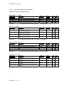
4.1.15
Limit values (Data record 21 and 22)
Limit values channel 1 (Data record 21)
Inputs (scaled values):
Meaning
Connection
(Parameter)
L_V1_ON_1_M
L_V1_OFF_1_M
L_V2_ON_1_M
L_V2_OFF_1_M
Table 4-12
DR21: Limit value 1 ON, Channel 1
DR21: Limit value 1 OFF, Channel 1
DR21: Limit value 2 ON, Channel 1
DR21: Limit value 2 OFF, Channel 1
Data type
REAL
REAL
REAL
REAL
Default
setting
10000.0
9990.0
1000.0
1010.0
Type
I
I
I
I
O&O
X
X
X
X
CFC–connections of SIWA_U08 – DS21 inputs, scaled values
Inputs (not scaled):
Meaning
Connection
(Parameter)
L_INT0_1_M
DR21: for internal use, Limit value 1 ON,
Channel 1 (not scaled)
DR21: for internal use, Limit value 1 OFF,
Channel 1 (not scaled)
DR21: for internal use, Limit value 2 ON,
Channel 1 (not scaled)
DR21: for internal use, Limit value 2 OFF,
Channel 1 (not scaled)
L_INT1_1_M
L_INT2_1_M
L_INT3_1_M
Table 4-13
Data type
Type
INT
Default
setting
10000
INT
9990
I
INT
1000
I
INT
1010
I
O&O
I
CFC–connections of SIWA_U08 – DS21 inputs, not scaled
Outputs (scaled values):
Connection
(Parameter)
L_V1_ON_1_O
L_V1_OFF_1_O
L_V2_ON_1_O
L_V2_OFF_1_O
Table 4-14
Meaning
DR21: Limit value 1 ON, Channel 1
DR21: Limit value 1 OFF, Channel 1
DR21: Limit value 2 ON, Channel 1
DR21: Limit value 2 OFF, Channel 1
Data type
REAL
REAL
REAL
REAL
Default
setting
10000.0
9990.0
1000.0
1010.0
Type
O&O
O
O
O
O
CFC–connections of SIWA_U08 – DS21 outputs, scaled values
Outputs (not scaled):
Connection
(Parameter)
L_V1_ON_NC_1_
O
L_V1_OFF_NC_1
_O
L_V2_ON_NC_1_
O
L_V2_OFF_NC_1
_O
Table 4-15
SIWAREX U
Meaning
DR21: Limit value 1 ON, Channel 1 (not
scaled)
DR21: Limit value 1 OFF, Channel 1 (not
scaled)
DR21: Limit value 2 ON, Channel 1 (not
scaled)
DR21: Limit value 2 OFF, Channel 1 (not
scaled)
Data type
Type
INT
Default
setting
10000
INT
9990
O
INT
1000
O
INT
1010
O
CFC–connections of SIWA_U08 – DS21 outputs, not scaled
4-21
O
O&O
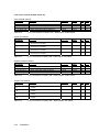
Limit values channel 2 (Data record 22)
Input (scaled values):
Connection
(Parameter)
L_V1_ON_2_M
L_V1_OFF_2_M
L_V2_ON_2_M
L_V2_OFF_2_M
Table 4-16
Meaning
DR22: Limit value 1 ON, Channel 2
DR22: Limit value 1 OFF, Channel 2
DR22: Limit value 2 ON, Channel 2
DR22: Limit value 2 OFF, Channel 2
Data type
REAL
REAL
REAL
REAL
Default
setting
10000.0
9990.0
1000.0
1010.0
Type
I
I
I
I
O&O
X
X
X
X
CFC–Aconnections of SIWA_U08 – DS22 inputs, scaled values
Inputs (not saled):
Meaning
Connection
(Parameter)
L_INT0_2_M
DR22: for internal use, Limit value 1 ON,
Channel 2 (not scaled)
DR22: for internal use, Limit value 1 OFF,
Channel 2 (not scaled)
DR22: for internal use, Limit value 2 ON,
Channel 2 (not scaled)
DR22: for internal use, Limit value 2 OFF,
Channel 2 (not scaled)
L_INT1_2_M
L_INT2_2_M
L_INT3_2_M
Table 4-17
Data type
Type
INT
Default
setting
10000
INT
9990
I
INT
1000
I
INT
1010
I
O&O
I
CFC–connections of SIWA_U08 – DS22 inputs, not scaled
Outputs (scaled values):
Meaning
Connection
(Parameter)
L_V1_ON_2_O
L_V1_OFF_2_O
L_V2_ON_2_O
L_V2_OFF_2_O
Table 4-18
DR22: Limit value 1 ON, Channel 2
DR22: Limit value 1 OFF, Channel 2
DR22: Limit value 2 ON, Channel 2
DR22: Limit value 2 OFF, Channel 2
Data type
REAL
REAL
REAL
REAL
Default
setting
10000.0
9990.0
1000.0
1010.0
Type
O&O
O
O
O
O
CFC–connections of SIWA_U08 – DS22 outputs, scaled values
Output (not scaled):
Meaning
Connection
(Parameter)
L_V1_ON_NC_2_
O
L_V1_OFF_NC_2
_O
L_V2_ON_NC_2_
O
L_V2_OFF_NC_2
_O
Table 4-19
4-22
DR22: Limit value 1 ON, Channel 2 (not
scaled)
DR22: Limit value 1 OFF, Channel 2 (not
scaled)
DR22: Limit value 2 ON, Channel 2 (not
scaled)
DR22: Limit value 2 OFF, Channel 2 (not
scaled)
Type
INT
Default
setting
10000
INT
9990
O
INT
1000
O
INT
1010
O
Data type
CFC–connections of SIWA_U08 – DS22 outputs, not scaled
SIWAREX U
O
O&O
Description of the CFCs
4.1.16
Process values (Data records 31 and 32)
Process values chammel 1 (Data record 31)
Output (scaled value):
Meaning
Connection
(Parameter)
GROSS_1_O
DR31: Gross value, Channel 1
Table 4-20
Data type
Default
setting
REAL
Type
O&O
O
X
Type
O&O
CFC–connections of SIWA_U08 – DS31 outputs, scaled value
Outputs (not scaled):
Connection
(Parameter)
GROSS_NC_1_O
ASYNC_E_1_O
SYNC_E_1_O
L_V1_1_O
L_V2_1_O
SC_A_1_O
UPD_B_1_O
LIFE_B_1_O
JOB_B_1_O
ST_CNT_1_O
DIG_V_NC_1_O
DCV24_1_O
RES131_1_O
RES231_1_O
RES331_1_O
RES431_1_O
RES531_1_O
RES631_1_O
RES731_1_O
ADC_L_1_O
V_MIN_1_O
W_DOG_1_O
EPROM_E_1_O
EEPROM_E_1_O
RAM_E_1_O
ADC_E_1_O
GR_OF_1_O
RES831_1_O
A_CMD_E_1_O
MFCT_1_O
SIWAREX U
4-23
Meaning
Data type
Default
setting
DR31: Gross value, Channel 1 (not scaled)
DR31: Asynchronous error (group error)
DR31: Synchronous error (group error)
DR31: Limit value 1, Channel 1
DR31: Limit value 2, Channel 1
DR31: Scale adjusted, Channel 1
DR31: Bit is inverted each time the Siwarex
U updates its measured value
DR31: Life bit used for I/O communication
DR31: Job acknowledgment bit used for I/O
communication
DR31: Status counter
DR31: Current digit value (filtered, not
scaled)
DR31: Asynchronous error: External supply
voltage 24V
DR31: Asynchronous error: Reserve
DR31: Asynchronous error: Reserve
DR31: Asynchronous error: Reserve
INT
BOOL
BOOL
BOOL
BOOL
BOOL
BOOL
O
O
O
O
O
O
O
X
X
X
X
X
X
X
BOOL
BOOL
O
O
X
X
BYTE
WORD
O
O
X
X
BOOL
O
X
BOOL
BOOL
BOOL
O
O
O
X
X
X
DR31: Asynchronous error: Reserve
DR31: Asynchronous error: Reserve
DR31: Asynchronous error: Reserve
DR31: Asynchronous error: Reserve
DR31: Asynchronous error: Control limit
ADC, Channel 1
DR31: Asynchronous error: Minimum
voltage on sense line, Channel 1
DR31: Asynchronous error: Watchdog
triggered
DR31: Asynchronous error: Error in EPROM
(program)
DR31: Asynchronous error: Error in
EEPROM (data)
DR31: Asynchronous error: Error in RAM
(read/writ error)
DR31: Asynchronous error: ADC error durin
read-access, Channel 1
DR31: Asynchronous error: Number for
gross weight overflow, Channel 1
DR31: Synchronous error: Reserve
DR31: Synchronous error: Distance to
adjustment points too small
DR31: Synchronous error: Job could not be
BOOL
BOOL
BOOL
BOOL
BOOL
O
O
O
O
O
X
X
X
X
X
BOOL
O
X
BOOL
O
X
BOOL
O
X
BOOL
O
X
BOOL
O
X
BOOL
O
X
BOOL
O
X
BYTE
BOOL
O
O
X
X
BOOL
O
X
Meaning
Connection
(Parameter)
executed due to malfunction
DR31: Synchronous error: A non-existent or
inactive channel was addressed
DR31: Synchronous error: Undefined code
or incorrect data in data records
DR31: Synchronous error: Wrong number
for data record
DR31: Synchronous error: Command not
possible since scales not adjusted
DR31: Synchronous error: Wait time of 5 sec
not adhered to during adjustment commands
DR31: Synchronous error: The adjustment
weight is negative
CH_E_1_O
CMD_E_1_O
DR_E_1_O
CMD_A_E_1_O
S5_PER_1_O
A_WGHT_N_1_O
Table 4-21
Type
O&O
BOOL
O
X
BOOL
O
X
BOOL
O
X
BOOL
O
X
BOOL
O
X
BOOL
O
X
Type
O&O
O
X
Type
O&O
INT
BOOL
BOOL
BOOL
BOOL
BOOL
BOOL
O
O
O
O
O
O
O
X
X
X
X
X
X
X
BOOL
BOOL
O
O
X
X
BYTE
WORD
O
O
X
X
BOOL
O
X
BOOL
BOOL
BOOL
BOOL
BOOL
BOOL
BOOL
BOOL
O
O
O
O
O
O
O
O
X
X
X
X
X
X
X
X
BOOL
O
X
Data type
Default
setting
CFC–connections of SIWA_U08 – D31 outputs, not scaled
Process values channel 2 (Data record 32)
Output (scaled value):
Connection
(Parameter)
GROSS_2_O
Table 4-22
Meaning
DR32: Gross value, Channel 2
Data type
Default
setting
REAL
CFC–connections of SIWA_U08 – DS32 output, scaled value
Output (not saled):
Connection
(Parameter)
GROSS_NC_2_O
ASYNC_E_2_O
SYNC_E_2_O
L_V1_2_O
L_V2_2_O
SC_A_2_O
UPD_B_2_O
LIFE_B_2_O
JOB_B_2_O
ST_CNT_2_O
DIG_V_NC_2_O
DCV24_2_O
RES132_2_O
RES232_2_O
RES332_2_O
RES432_2_O
RES532_2_O
RES632_2_O
RES732_2_O
ADC_L_2_O
V_MIN_2_O
4-24
SIWAREX U
Meaning
DR32: Gross value, Channel 2 (not scaled)
DR32: Asynchronous error (group error)
DR32: Synchronous error (group error)
DR32: Limit value 1, Channel 2
DR32: Limit value 2, Channel 2
DR32: Scale adjusted, Channel 2
DR32: Bit is inverted each time the Siwarex
U updates its measured value
DR32: Life bit used for I/O communication
DR32: Job acknowledgment bit used for I/O
communication
DR32: Status counter
DR32: Current digit value (filtered, not
scaled)
DR32: Asynchronous error: External supply
voltage 24V
DR32: Asynchronous error: Reserve
DR32: Asynchronous error: Reserve
DR32: Asynchronous error: Reserve
DR32: Asynchronous error: Reserve
DR32: Asynchronous error: Reserve
DR32: Asynchronous error: Reserve
DR32: Asynchronous error: Reserve
DR32: Asynchronous error: Control limit
ADC, Channel 2
DR32: Asynchronous error: Minimum
voltage on sense line, Channel 2
Data type
Default
setting
Description of the CFCs
Meaning
Connection
(Parameter)
W_DOG_2_O
DR32: Asynchronous error: Watchdog
triggered
DR32: Asynchronous error: Error in EPROM
(program)
DR32: Asynchronous error: Error in
EEPROM (data)
DR32: Asynchronous error: Error in RAM
(read/writ error)
DR32: Asynchronous error: ADC error
during read-access, Channel 2
DR32: Asynchronous error: Number for
gross weight overflow, Channel 2
DR32: Synchronous error: Reserve
DR32: Synchronous error: Distance to
adjustment points too small
DR32: Synchronous error: Job could not be
executed due to malfunction
DR32: Synchronous error: A non-existent or
inactive channel was addressed
DR32: Synchronous error: Undefined code
or incorrect data in data records
DR32: Synchronous error: Wrong number
for data record
DR32: Synchronous error: Command not
possible since scales not adjusted
DR32: Synchronous error: Wait time of 5 sec
not adhered to during adjustment commands
DR32: Synchronous error: The adjustment
weight is negative
EPROM_E_2_O
EEPROM_E_2_O
RAM_E_2_O
ADC_E_2_O
GR_OF_2_O
RES832_2_O
A_CMD_E_2_O
MFCT_2_O
CH_E_2_O
CMD_E_2_O
DR_E_2_O
CMD_A_E_2_O
S5_PER_2_O
A_WGHT_N_2_O
Table 4-23
4.1.17
Type
O&O
BOOL
O
X
BOOL
O
X
BOOL
O
X
BOOL
O
X
BOOL
O
X
BOOL
O
X
BYTE
BOOL
O
O
X
X
BOOL
O
X
BOOL
O
X
BOOL
O
X
BOOL
O
X
BOOL
O
X
BOOL
O
X
BOOL
O
X
Type
O&O
O
O
O
O
O
O
X
X
X
X
X
X
Data type
Default
setting
CFC–connections of SIWA_U08 – D32 outputs, not scaled
Modul info (data record 40)
Outputs:
Connection
(Parameter)
VER_O
CH_SUM_O
RES140_O
CH_O
MOD_T_O
I_CNT_O
Table 4-24
SIWAREX U
Meaning
DR40: FW version
DR40: Checksum
DR40: Reserve
DR40: Depends on number of channels
DR40: 0=7MH4601... 1=7MH4950....
DR40: Internal counter
Data type
WORD
WORD
BYTE
BYTE
BYTE
BYTE
CFC–connections of SIWA_U08 – DS40 outputs
4-25
Default
setting
4.2
4.2.1
CFC CMD_SU08 (FB651)
Calling OBs
The block should be installed in the timed interrupt OB, in which the associated
driver block of the Siwarex-module is also processed (e.g. OB32). The block must
also be installed in the OB100 (carried out automatically in CFC):
4.2.2
Start-up characteristics
Internal flag variables are reset on start-up to enable every pending input bit to be
identified as a positive edge and the corresponding command to be issued
following initialization.
4.2.3
Function and functional principle
The CMD_SU08 block acts as the connection block for the driver block's automatic
commands for controlling a Siwarex U module (SIWA_U08).
There is an input bit for every possible command code and for reading and writing
data records. The corresponding command is initiated when the input bit has a
positive edge. If several commands are started simultaneously, they are routed to
the SIWA_U08 block sequentially. After a command is executed, the subsequent
pending command to be executed is searched for from its position. Command
codes pending at inputs HPRIO1..5 are executed with a higher priority than all
other commands (HPRIO1 has the highest priority) and, if necessary, also interrupt
linked commands (CMD_601 to 699).
Commands are not routed from the CMD_SU08 command block to the SIWA_U08
driver block when in manual mode.
4-26
SIWAREX U
Description of the CFCs
4.2.4
Interconnection with SIWA_U08 block
Inputs MAN_AUT, CMD_FOK and CMD_ERR of the CMD_AWI block must be
connected to outputs QMAN_AUT, CMD_FOK and CMD_ERR of the SFT_AWI
block. Outputs AUT_CMD and AUTCMDEN are connected to the SFT_AWI block
inputs of the same name.
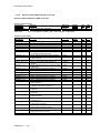
4.2.5
I/Os of CMD_SU08
Connection
(Parameter)
Meaning
MAN_AUT
CMD_FOK
CMD_ERR
HPRIO1..5
CMD01..CMD199
RD_DR1..130
WR_DR1..130
CMD601..699
RESET
AUT_CMD
AUTCMDEN
1=AUTO, 0=MANUAL Mode (for
connection with QMAN_AUT of
SIWA_SU08)
Command ended without error (for
connection with CMD_FOK of
SIWA_SU08)I)
Command ended with error (for
connection with CMD_ERR of
SIWA_SU08))
Commands executed with higher priority
(HPPRIO1 has the highest priority)
Commands 1 to 199
Read data record 1..130
Write data record 1..130
Commands 601..699 (linked
commands)
Reset block
Automatic error codes (for connection
with AUT_CMD of SIWA_SU08))
1= Execute automatic command (for
connection with AUTCMDEN of
SIWA_SU08))
Table 4-25
CFC – Connections of CMD_SU08
SIWAREX U
4-27
Data type
Default
setting
Type O&O
BOOL
FALSE
I
BOOL
FALSE
I
BOOL
FALSE
I
INT
I
BOOL
BOOL
BOOL
BOOL
HPRIO
1..5: 0
FALSE
FALSE
FALSE
FALSE
I
I
I
I
BOOL
BOOL
FALSE
FALSE
IO
O
BOOL
FALSE
O
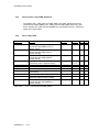
4.3
MOD_SU08 (FB662)
4.3.1
Area of application
The block acts as the interface of a Siwarex scale module for the PCS 7
maintenance station
4.3.2
Calling OBs
Timed interrupt OB, in which you install the block (e.g. OB32). The block must also
be installed in the following OBs in the run sequence (carried out automatically in
CFC):
OB100
4.3.3
Restart
Use in CFC
The CFC function "Generate module drivers" automatically:
•
Installs the MOD_SIWA block in its runtime group at the blocks named
above, downstream from the RACK block runtime group
•
Configures the inputs SLOT, RACK_NO, SUBN1_ID, SUBN2_ID
•
Interconnects
- inputs PERAF, MODF and RACKF are connected to outputs QPERAF,
QMODF and QRACKF of the corresponding MOD_1-block
- inputs PARF and PA_DIAG are connected to outputs QPARF und ODIAG
of the corresponding Siwarex driver block
4.3.4
Function
The block forms the maintenance state (MS) for the Siwarex module and sends the
corresponding messages to WinCC.
MS
0, good
7, maintenance; need high
8, uncertain
Table 4-26
4-28
Condition
No error
Module removed/defective (MODF = 1) or
Module not operative (PA_DIAG = 16#0100)
Rack error (RACKF = 1)
Maintenance-States of MOD_SU08
SIWAREX U
Description of the CFCs
4.3.5
Message text and message class assigned to the block parameters
Message
block
ALARM_8P
EV_ID
Table 4-27
4.3.6
Block parameter
Default message text
Message
class
1
QMODF
S
2
QPARF
3
QPERAF
4
QMOD_ERR
Device @1%d@/ @2%d@/
@3%d@: Withdrawn
Device @1%d@/ @2%d@/
@3%d@: Configuration error
Device @1%d@/ @2%d@/
@3%d@: Access error
Device @1%d@/ @2%d@/
@3%d@: bad, maintenance alarm
Message
no.
S
S
CFC Message texts of MOD_SU08
Assignment of associated values to the block parameters of MOD_SIWA
Message
block
ALARM_8P
EV_ID
Table 4-28
4.3.7
S
Message
no.
Block
parameter
Meaning
1
2
3
SUBN1_ID
RACK_NO
SLOT_NO
Number DP master system
Subassembly support/station number
Slot number
CFC associated values of MOD_SU08
I/Os von MOD_SU08
Connection
(Parameter)
CH_EXIST
CH_OK
EN_MSG
EV_ID
MODF
MS
MSG_ACK
MSG_STAT
O_MS
PA_DIAG
PARF
PERAF
QERR
QMODF
QMSG_SUP
QMSGERR
SIWAREX U
Meaning
Data type
Channel available
Channel OK
1 = Message cleared
Message number
1 = Module removed/defective
Maintenance status
Message acknowledgement
Message error information
Maintenance status
PA diagnostic information
1 = Configuration error
1 = Peripheral access failure
1 = Error
1 = Module removed/defective
1 = Message suppression active
1 = Message error
DWORD
DWORD
BOOL
DWORD
BOOL
DWORD
WORD
WORD
DWORD
DWORD
BOOL
BOOL
BOOL
BOOL
BOOL
BOOL
4-29
Default
setting
0
0
TRUE
0
FALSE
0
0
0
0
0
FALSE
FALSE
FALSE
FALSE
FALSE
FALSE
Type O&O
O
O
I
I
I
I
O
O
O
I
I
I
O
O
O
O
+
+
+
+
QMOD_ERR
QPARF
QPERAF
QRACKF
RACK_NO
RACKF
RUNUPCYC
SLOT_NO
SUBN1_ID
SUBN2_ID
1 = Siwarex module error
1 = Parameterization failure
1 = Peripheral access error
1 = Subassembly support/station error
Subassembly support number
1 = Subassembly support/station error
Initialization cycles
Slot number
Number of the primary DP master system
Number of the redundant DP master system
Table 4-29 CFC – connections of MOD_SU08
4-30
SIWAREX U
BOOL
BOOL
BOOL
BOOL
BYTE
BOOL
INT
BYTE
BYTE
BYTE
FALSE
FALSE
FALSE
FALSE
0
FALSE
10
0
16#FF
16#FF
O
O
O
O
I
I
I
I
I
I
Description of the Faceplates
5 Description of the Faceplates
5.1
General
Operation and monitoring of the scale via WinCC faceplates is described below.
Descriptions of the individual scales parameters and scale functions are provided
in the SIWAREX U manual and are not explained individually where each faceplate
is displayed.
The example faceplate for the SIWAREX U modules was created with the
Faceplate Designer from PCS7 version 6.1. The WinCC images and scripts that
are created can be modified according to individual requirements.
Every time a new view is opened, the displayed parameters are read. Data is not
reread when tabs within a view are switched. Data can be updated at any time by
clicking the "Receive Data" button.
5.2
Calling Up Faceplates
The process for calling up faceplates can be configured in the Graphics Designer
(Dynamic Wizard -> Picture Functions -> Picture selection via measurement point).
The faceplates themselves can be called up via the Typical provided.
5 different typicals are available, one with weight display and a second with silo
and weight display.
Alternative 1:
Alternative 2:
Alternative 3:
SIWAREX U
5-31
Alternative 4:
Alternative 5:
The Typical is defined in CFC SIWA_U08. A checkmark is set against "Create
block icon" in CFC properties. The Typical is defined in the field underneath:
Blank, 1
: Typical with 2 weight displays for 2 channels
2
: Typical with 2 weight displays and 2 silos
3
: Typical with 2 weight displays and one silo
4
: Typical with one weight displays (channel 1)
5
: Typical with one weight displays (channel 1) and one silo
0, >5
: no typical
The selection is imported into the OS through OS compilation.
5.3
Faceplate Display in OS
All views of the sample faceplate including their functions are shown in the
following sections.
5-32
SIWAREX U
Description of the Faceplates
5.3.1
Standard View
The standard view displays the current weight value of the scale and a number of
selected statuses. The Manual/Automatic operating modes can also be switched.
When only channel 1 is active, the view of channel 2 is masked. For this first the
data record 40 has to be read.
In automatic mode, only reading of data records is permitted.
Fig 5-1
5.3.2
Standard view for SIWAREX U
Service view
There are two separate service views for channel 1 and channel 2, which are
designed identically.
There are three service tabs.
Editing the tab calibration enables scale adjustment from the OS. Here core
parameters for data records 3 (channel 1) and 4 (channel 2) are set. Limits can be
set in the Limits tab. Scale commands can be issued in the Operation tab and so
the scale can be operated.
SIWAREX U
5-33
Fig. 5-2
View calibration channel1
ATTENTION: Before the input of the weight values first the decimal place has to
be set.
Fig. 5-3
5-34
View limits channel 1
SIWAREX U
Description of the Faceplates
Fig. 5-4
5.4
View operation channel 1
Faceplate creation
Mainly, those standard items that are described in the documentation on the
Faceplate Designer and that have been delivered with the Faceplate Designer are
used. This description concentrates on the features that have been implemented
for the SIWAREX U Faceplate.
Tabs
To help clarify matters, two Faceplate view with up to 4 tabs have been shown in
different images. Switching between the tabs is done using function
„SH6_ChangeView_tab.fct“. Each tab must have the name of the image that it is
calling.
Reading data record during selection of faceplate view
A command to read data displayed in the faceplate view is always issued for the
FP_CMD manual input when a new view is added in the faceplate. The function
block copies the value from FP_CMD to the MAN_CMD manual input when no
other command (MAN_CMD=0) is present here. This prevents any potential
commands pending at the MAN_CMD input from being overwritten when the view
in the faceplate is changed.
SIWAREX U
5-35
The button used to read data is inactive while a data record is being read, in order
to indicate this.
Operating authorization
In every view, an element having the name „Level5_MODE“ or „Level6_MODE“ is
found. These elements do not only the enable operating authorization from the
User Administrator but they also deny operating authorization in Automatic
operating mode. This is done with function „SH6_CheckPermission_Plus.fct“,
which is called when the image is loaded and when the operating mode is
changed. Passing the operating mode to the individual elements is performed
through direct connections.
Only the Manual-Automatic switch with the "single operating authorization" (level5)
can be used with the default settings. All other operations require the "higher value
operating authorization“ (level6).
Combo-boxes with several entries
Various combo-boxes have 3 or more entries. These combo-boxes are described
further using an example of the combo-box for the dosing commands.
With a mouse click on the combo-box, the image
„@PG_SIWA08_SCROLL_WEIGHING_CH1.pdl“ is opened.
The image „@PG_SIWA_U08_SCROLL_WEIGHING_CH1.pdl“ is based on the
„@FPD_BedAnalog.PDL“ image. The main difference is that the analog value is
not entered in the IO-field, instead, a command which has an analog value
assigned as the command code is selected. The commands are listed in individual
text fields in the image @PG_SIWA_U08_CMD_WEIGHING.pdl“:
Fig. 5-5
Command selection
While selecting a command with the mouse, the command code is written into the
IO-field "Value" of the „@PG_SIWA_U08_SCROLL_WEIGHING.pdl“ image. If the
output value „Value“ is changed then the transmitted command is highlighted in
colour and the respective command code is transferred to the block with „OK“.
5-36
SIWAREX U
Configuration Example
6 Configuration Example
One of the sample projects in SIMATIC Manager is the zXy70_06_SIWAREX_U08
project; this allows a PCS7 configuration for SIWAREX U to be quickly and easily
established through several adjustments to its own environment. The example is
applicable to two scales. For instance, SIWA_U08 is configured for one scale,
while SIWA_U08 in conjunction with CMD_SU08 is configured for the other.
For the project to be adapted, the following must be carried out in particular:
SIWAREX U
-
the hardware configuration must be adapted
-
connections must be secured
-
suitable addresses must be configured on SIWA_U08.
6-37
7 Abbreviations
AS
CFC
DO
DI
DR
FC
FB
HSP
HW
OS
PC
SFC
SIWATOOL
7-38
Automation system
Continuous Function Chart (PCS7)
Digital output
Digital input
Data record
STEP7 Function call
Function block
Hardware Support Package
Hardware
Operator Station
Personal-Computer
System Function Call (System function)
Windows-Software Commissioning and Service of SIWAREX FTA
SIWAREX U