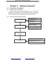
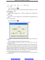
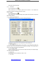
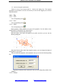
1
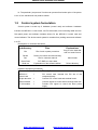
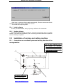
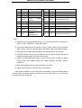
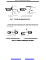
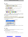
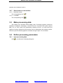
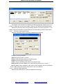
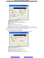
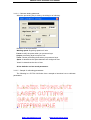
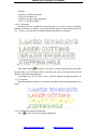
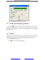
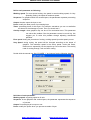
Redsail Laser machine user manual
Chapter 1 BASIC KNOWLEDGE OF
SOFTWARE SYSTEM
1.1
Introduction of software:
The software is made for large-area laser machine, particularly for high-speed
engraving and cutting.
The following is the main features and functions of this software.
A、It can support AI, BMP, PLT, DST (embroidery software) and DXF etc.
B 、 After graphics input, you can do some simple editing (change the size,
circumrotate and copy etc.).
C、Data of different layers can be output respectively. Power, speed and mode
(engrave and cut etc.) of each layer can be set respectively. All the parameters will be
saved automatically.
D、Graphics can be engraved; Vector graph can be drawn, cut and engraved;
precise level can be set up freely.
E、Support array output and the software can calculate the number of data to cover
the material. Whole processing procedure can be simulated on screen. The original point
can be set anywhere to make processing conveniently.
F 、When process is going on, it can be controlled by “Pause” and “Continue”. All
output process can be controlled on the interface of machine.
G、When output, “process along dialog box” can make feeding and location easier.
H、Engraving speed can reach to 1500mm/s, cutting speed can reach to 500mm/s,
engraving precision can reach to 0.1mm.
I、360 degree grade engraving. The grade can be set freely.
J、Mass graphics(›15M) can be calculated rapidly.
K、When the speed changes, the power intensity will change automatically. It can
insure the process depth is constant.
L、Excellent optimized-path and path definition.
M、When cutting, you can add assistant lines. This can make the juncture smooth
and output quality is increased.
http://www.hflaser.com
http://www.easycut.cn
Redsail Laser machine user manual
N、The particular “part process” function can process from broken point. If the power
is cut off, the machine will not produce waster.
1.2
Control system formulation
Control system is made up of hardware (control card) and software. Hardware
includes one MPC03-LV control card, one FV100 module, one connecting cable and one
P68 patch panel; and software includes drivers for the MPC03-LV control card and
control software. The whole control system is contained in a packing carton and software
in a CD.
Descriptions on software directories:
subdirectory
Files
Explanations
Bin
File of main system procedure
Copy it to the hard disk
and run LaserCut.exe
Drivers
Drivers for control card and soft dog
Doc
File for customer manual
Demo Data
PLT, BMP etc. demo data
Read me
Explanations of the software edition
Word format
Drivers directory
Hardware equipment formulation:
Item
Amount Description
MPC03-LV
control card
68-pin data wire
Terminal board
FV100 module
1
1
1
1
PCI control card, inserted into PCI slot of the
computer directly
Connect PCI control card and terminal board
Connect signals to control device through data wire
Provide 0-5V signal to control the laser power
supply
http://www.hflaser.com
http://www.easycut.cn
Redsail Laser machine user manual
Chapter 2
System Configuration &
Installation
2.1 The condition for installing software system
A、Operation system: Windows 2000 or Windows XP of Chinese or English version
B、Hardware requirement: IBM compatible computer
C、Basal running collocation:
CPU: Above Pentium 2;
Storage: 128 Meg;
Hardware: Above 10 G and CD-ROM;
PCI extending slot;
Above one USB interface;
2.2
hardware installation
2.2.1
Copy files
Copy content of CD to the computer hard disk, software contains generally the
following:
2.2.2
Install USB DOG
There is a USB DOG in machine package that should be inserted in any USB slot of
the computer. After this, there is an instruction to find new hardware. At first, please
choose “cancel” and then run the file Drivers\ MicroDogInstdrv.exe in CD. You will see
the dialog box as following:
http://www.hflaser.com
http://www.easycut.cn
Redsail Laser machine user manual
Please press “install Driver” button to install the driver of DOG.
2.2.3
Install movement-control card
There is a PCI movement-control card in machine package. This card is based on
PCI bus and should be inserted to PCI slot of the computer. To ensure your safety, the
following procedure should be abided by:
A、Close PC, and cut off power.
B 、 Open PC's cover, choose the PCI slot that is not in use and insert
movement-control card.
C、Fix movement-control card, and put cover on computer as it is.
D、Connect movement-control card with laser machine by data wire that is attached
with machine.
E、Connect with power and start to run PC.
When operating system is started, the PCI card can be checked automatically. There
is an instruction to find new hardware. At first, please choose “cancel” and then run the
file Drivers\ Win98-2000 (Win XP)\SetupMpc03Drv.exe in CD. You will see the dialog box
as following:
http://www.hflaser.com
http://www.easycut.cn
Redsail Laser machine user manual
Click “Setup”, the driver will be installed automatically. There are some notes for this
operation, please read the file “readme.TXT” at first.
Then restart the computer please.
2.2.4
Install software
It is easy to install software, and you just copy all files in CD to hardware.
2.2.5
Update software
The software will be updated according to customer’s requirement. When you update
software, just replace the subdirectory “Bin”. All driving procedure and basic system file
are not necessary to updated.
2.3
Installation of carving and cutting machine
2.3.1 Conventions on coordinate system and moving direction of the
carving machine
2
3
2, on the upper right/left corner of
the
system
is
maximum
coordinates of X and Y where
switches of the system origin
signals should be installed
1
X 1 Y1
X 2 Y1
Y
O
X
X 1 Y2
X 2 Y2
4
5
6
7
3, Starting point of X,
Y coordinates (0,0),
http://www.hflaser.com
http://www.easycut.cn
Redsail Laser machine user manual
1, The lateral is axis X and
the longitudinal is axis Y;
axis X to the right is positive
and axis Y upward is positive
1、Laser tube
2、The first reflect mirror
3、The second reflect mirror
4、The third reflect mirror
5、Focus lens
6、Material
7、Working table
2.3.2 Connect step motor driver, switching power supply, step
motor and on/off signals of the origin according to requirements shown
below.
Description of pins on the connection:
No.
Name
Definition
No.
1
2
3
4
5
6
Name
Definition
7
EA2+
5Vpower +
8
EA2-
Pause
9
EB2+
5Vpower +
10
EB2-
Back to the origin
11
EZ2+
5Vpower +
12
EZ2-
Sudden stop
14
GND5
5V power grounding
18
FRQ
Laser regulation
13
15
LASER
Laser output
17
16
19
PUL2-
Pulse 2-
20
PUL2+
Pulse 2+
21
DIR2-
Direction 2-
22
DIR2+
Direction 2+
23
24
DCV5
5V power positive
25
26
ORG2
Origin 2
27
28
EL2+
Positive limit 2
29
30
EL2-
Negative limit 2
31
32
SD2+
Positive deceleration 2
33
34
SD2-
Negative deceleration 2
35
EA3+
5Vpower+
36
EA3-
Downward shift
37
EB3+
5Vpower+
38
EB3-
Right shift
39
EZ3+
5Vpower+
40
EZ3-
Upward shift
41
EA4+
5Vpower+
42
EA4-
Along border
43
EB4+
5Vpower+
44
EB4-
Start / Continue
45
EZ4+
5Vpower+
46
EZ4-
Left shift
47
48
http://www.hflaser.com
http://www.easycut.cn
Redsail Laser machine user manual
49
PUL3-
Pulse 3-
50
PUL3+
Pulse 3+
51
DIR3-
Direction 3-
52
DIR3+
Direction 3+
53
PUL4-
Pulse 4-
54
PUL4+
Pulse 4+
55
DIR4-
Direction 4-
56
DIR4+
Direction 4+
57
DCV24
+24V
positive
58
ALM
External alarm input
59
ORG3
Origin 3
60
ORG4
Origin 4
61
EL3+
Positive limit 3
62
EL4+
Positive limit 4
63
EL3-
Negative limit 3
64
EL4-
Negative limit 4
65
SD3+
Positive
deceleration 3
66
SD4+
Positive deceleration 4
67
SD3-
Negative
deceleration 3
68
SD4-
Negative deceleration 4
power
Note:
A. Excepting universal input/output signals, 2, 3, 4 of the signal name correspond to
shaft 2, 3 and 4 of MPC03-LV card respectively.
B. This control system needs only shaft 2, 3 and 4. Shaft 3 refers to axis Y (pushing
shaft), shaft 4 to axis X (scanning shaft), and shaft 2 used for automatic feeding.
C. Grounding wire of laser signal should be connected with that of 5V power.
D. 24V power doesn’t have to be grounded. As long as it has enough driving power
towards the origin switch, 5V power can be used.
E. Switching power determines whether control card can work normally, so please
choose power with reliable quality that voltage regulator and filter circuit is
necessary.
F. Red mark indicates that the system should be connected.
G. Origin switch requires low electric level to be effective.
Input signals of MPC03-LV card (travel limit, deceleration, origin and external alarm)
could be output by contact switch or proximity sensor of NPN output etc. Its connecting
method is as shown in diagram.
http://www.hflaser.com
http://www.easycut.cn
Redsail Laser machine user manual
24DCV
24DCV
Upward pull resistor
Optical
cadmium
power
supply
Optical
grounding
MPC03 Card External Signal
a. Contact switch
cadmium
power
supply grounding
MPC03 Card External Signal
b. Proximity switch for NPN output
Fig. 2.1
Connecting methods for on-off input signal
Pulse/direction output signal of MPC03-LV card, as control signal of stepping motor
or digital AC servo motor, its frequency determines rate of rotation of the motor and its
number determines angle of rotation. Connecting method for pulse/direction signal is as
shown in diagram:
+
+
-
GND
MPC03 Card
+5V
26LS32
or
equivalent
circuit
Driver
a. Connecting method for differential signal
+
MPC03 Card
Driver
b. Connecting method for single end signal
Fig. 2.2 Connecting method for pulse/direction output signal
http://www.hflaser.com
http://www.easycut.cn
Redsail Laser machine user manual
24
+5
16
15
MPC03 Card
Laser Tube
Fig. 2.3 diagram Connecting method 2 for laser output signal
16
15
14
+5V Power Grounding
MPC03 Card
Laser Tube
Fig. 2.4Connecting method 2 for laser output
signal
http://www.hflaser.com
http://www.easycut.cn
Redsail Laser machine user manual
Chapter 3
Software operation
3.1
Procedure of operation
3.1.1
Main procedure of operation
Procedure: make graphics in CorelDraw (version 9.0, 11.0 and 12.0 are
supported by this system), Photoshop, AutoCAD2000 or DST. Start software
system, load data that is needed to process. Then please collocating parameters of
processing data and creating processing file and output data for processing.
3.1.2
Flow chart of processing procedure
CorelDraw (PLT、BMP)
Make processing data
PhotoShop (BMP)
AutoCAD (DXF)
Input processing data
Define processing data
Location of makeup
Define processing parameter
Produce processing
document
(.LAS file)
Manual location, process along frame
Output
Processing procedure control
Automatic process time
http://www.hflaser.com
http://www.easycut.cn
Redsail Laser machine user manual
3.2
Explanation for system function
When you start software, you will see the interface as follows.
can be found on tool columns.
Save data
Set array word
Import data
Scale geometry
Edit tools bar
All system function
Optimize route
Set origin position
Layer tools bar
Test machine
Simulation
Status bar
Let mouse stay on an icon for a moment, and you can see the explanation of basic
function of tools bar. The following is the explanation of all tool columns.
3.2.1
File
3.2.1.1 New
The corresponding icon is
.
Create a new file.
3.2.1.2 Open
The corresponding icon is
.
Load data that the software supports. The software can support ﹡.LAS、
http://www.hflaser.com
http://www.easycut.cn
Output
Redsail Laser machine user manual
﹡.PLT、﹡.BMP、﹡.DXF、﹡.DST、﹡.AI、﹡.Dwg2 etc. files.
3.2.1.3 Save
The corresponding icon is
.
Save the graph data that is defined processing parameters as laser
machining file (﹡.LAS).
3.2.1.4 Save As
Save a laser machining file (﹡.LAS) as another laser machining file
(﹡.LAS).
3.2.1.5 Export
Save the vector graph data that is in current window as a standard PLT file
(*.PLT).
3.2.1.6 Test machine
The corresponding icon is
.
Click this button, and then you can see the following dialog box:
Up, Down, Left, Right: Move the laser head. Click once and the laser head will move
a distance.
Length: It determines the distance that the laser head moves.
Power: It determines the intensity of the laser. The minimum value is 0 and the
maximum value is 100.
Adjustment: Click this button and the laser head will move to the home point of the
machine slowly (the speed is determined by “Slow Speed” that you can change in the
“Machine Parameters Setting” diagram). Then the laser head will move to the origin point
quickly (the speed is determined by “Fast Speed” that you can change in the “Machine
Parameters Setting” diagram). This can eliminate the cumulate error. Generally, the
machine should be adjusted before processing. When you run the software, it will be
adjusted automatically (this function can be cancelled as you prefer).
To Define Origin: Click this button and the laser head will move to the origin point of
the machine quickly.
http://www.hflaser.com
http://www.easycut.cn
Redsail Laser machine user manual
Close laser: Open/Close laser.
3.2.1.7 Simulation
The corresponding icon is
.
When parameters set is finished, please click this button. It can simulate the
procedure of output for checking the result of output.
3.2.1.8 Output
.
The corresponding icon is
After confirming the result of simulating output, please click this button to output the
data to laser machine.
3.2.1.9 Machine parameters set
Click this button, and then you can see the following dialog box:
Explanation for the function of each parameter in above dialog box:
1、 Table range X(Y)
It is the available processing area of the machine. If you change the number, the
reference frame of the main interface will be changed accordingly. The moving range of
X and Y axis will be restricted by this parameter.
2、X (Y, Z) Each Length
When the stepping motor moves a circuit, the laser head will move a relative length.
You need to input the number in it.
3、Need Pulse
The number is “driver’s subdivision number” ×200.
4、Fast speed
http://www.hflaser.com
http://www.easycut.cn
Redsail Laser machine user manual
This is the maximum speed of laser head moving without lasers emitting. When you
move the laser head up, down, left and right, this parameter will work. If the number is
too high, machine will shake intensively.
5、Slow speed
6、Acceleration (fast)
7、Acceleration (slow)
8、Start speed
X, Y -Axis start speed means starting speed. When cutting, the number is the
starting speed of acceleration on X, Y-axis. Normally, the number should be chosen from
5-20mm/s according to different graphics. If the number set up is too high, machine will
shake intensively.
9、even speed
10、Cancel Time Limit
10、Start-Auto-GoHome
11、X-Axis Home Dir
It is determined by the position of original switch.
3.2.1.10 Engraving parameters set
Click this button, and then you can see the following dialog box:
Now let’s use the first row as an example to explain each parameter:
http://www.hflaser.com
http://www.easycut.cn
Redsail Laser machine user manual
This row represents that when engraving speed (engraving speed is set up in “Layer
Properties” which is in “Layers manager”) is between1000 to 1200, acceleration is 30mm.
That is, the engraving length without laser. This function is used for conquering inertia of
machine. If you find graphics error happens (that is, motor lost step), you can set up a
bigger number in “Speed du…”
“Add Space” is used for compensating mechanical returning clearance. If you find
the engraving edge is not orderly, you can set up number in “Add Space”. This number
can be a positive number or a negative number. The details are in the “Add Space
Adjustment” part that is in the part “Modify” of Chapter Four.
When all the parameters are set, click “save” button please, then click “close” to
escape.
3.2.1.11 Cutting parameters set
Click this button, and then you can see the following dialog box:
Acceleration
It determines the time that starting speed reaches to maximum speed. If the number
set up is too high, machine will shake intensively. If the number set up is too low,
processing efficiency will be lowered. So modify it according to actual situation.
Min acceleration
It determines the processing precise when the processing route turns the corner.
Max Speed:During cutting, it determines the speed when the laser is not emitting.
3.2.1.12 Exit
Click this button, and you can exit the software.
5、Scan Y axis speed
When engraving, the Y-axis’s moving speed.
6、Slow speed
The starting speed of laser head moving without lasers emitting. If the number set
up is too high, machine will shake intensively.
9、Slow acceleration
http://www.hflaser.com
http://www.easycut.cn
Redsail Laser machine user manual
13、List for set engrave parameters
There is a list on the second half of “archive set” dialog box. The engrave
parameters of movement on X-axis can be set up in this list. We suggest you to choose
Windows default.
3.2.2
File
3.2.2.1 Undo
The corresponding icon is
.
3.2.2.2 Redo
The corresponding icon is
3.2.2.3 Select
.
The corresponding icon is
.
Select graphics. Select graphics or a part of the graphics. You can delete, move,
change layers of the graphics you select and etc.
There are other functions about this button:
Click this button, and select the graphics you prefer, and then you can see the
following dialog box:
Move the mouse to the nodes, then drag the mouse, you can change the shape of
the graphics as you prefer.
After you select the graphics, click “Spacebar” and you can see the following dialog
box:
Input the coordinate of the X-axis and Y-axis, you can change the position of the
graphics.
3.2.2.4 Enlarge
http://www.hflaser.com
http://www.easycut.cn
Redsail Laser machine user manual
The corresponding icon is
.
Enlarge showing graphics. Click this button, then click your graphics with mouse
and the graphics can be enlarged for show.
3.2.2.5 Reduce
.
The corresponding icon is
Reduce showing graphics. Click this button, and the graphics can be reduced for
show.
3.2.2.6 Move
The corresponding icon is
.
Move screen. Click this button; press the left button of your mouse continuously, and
move your mouse on any place of the graphics, then the graphics can move.
3.2.2.7 Worktable range
The corresponding icon is
.
Show the whole processing area within the scale of reference frame.
3.2.2.8 Data range
The corresponding icon is .
Show the processing area completely. It can show the processing date in max on
screen.
3.2.2.8 Move data to reference frame
When the data is input, it may be out of the reference frame. Click this button and
you can move data to reference frame.
3.2.3
Drawing
3.2.3.1 Draw lines
The corresponding icon is
.
Click this button, move your mouse on the screen, and you can draw straight lines
freely. Press “Ctrl” key, and move mouse on the screen, you can draw horizontal lines.
3.2.3.2 Draw rectangle
The corresponding icon is
.
Click this button, move your mouse on the screen, and you can draw rectangles of
various sizes. Press “Ctrl” key, and move mouse on the screen, you can draw square.
3.2.3.3 Draw continual line
The corresponding icon is
.
3.2.3.4 Draw ellipse
The corresponding icon is
3.2.3.5 Array copy
.
The corresponding icon is
.
Click “choose” button
, and choose the graphics you want to array copy then click
http://www.hflaser.com
http://www.easycut.cn
Redsail Laser machine user manual
this button, you will see following dialog box.
Input relative parameters, then a number of graphics are copied as “number of rows X
number of columns”.
3.2.3.6 Circumrotate
3.2.3.7 Mirror vertical
The corresponding icon is
3.2.3.8 Mirror horizon
.
The corresponding icon is
3.2.3.9 Change size
.
The corresponding icon is
.
Change the size of graphics. Click “select” button
, then select the graphics you
want to process and click the button, you can see the dialog box as follows.
Now, input the number you prefer on X and Y-axis. Click “OK”, the size of graphics
can be changed. If you don’t want to change the proportion of X and Y-axis, you can
input one of the number (X or Y), then click the button
3.2.4
.
Tools
3.2.4.1 Draw lines
http://www.hflaser.com
http://www.easycut.cn
Redsail Laser machine user manual
3.2.5
View
3.2.5.1 Tool bar
Standard tool bar: Click this button, you can display or hide the following bar.
Technics tool bar: Click this button, you can display or hide the following bar.
Edit tool bar: Click this button, you can display or hide the following bar.
Layer tool bar: Click this button, you can display or hide the following bar.
Click “select” button
and choose a certain part of graphics on screen (after
choosing, the outline become gray), then click any color button you prefer on the layer
bar. Now a new layer will be added in the layer list automatically.
3.2.5.2 Status bar
Click this button, you can display or hide the following bar.
The status bar show the coordinates of the position that mouse stay on. It also show
the name and website of the manufacturer.
3.2.5.3 Language
Click this button, and you can see the following dialog box.
Select the language you need, and restart the software. The interface will display
the language you need.
3.2.6
Help
3.2.6.1 Catalog
Click this button, and you can see the manual of the software. You can get any
information about how to operate the software.
3.2.6.2 Version message
Click this button, and you can see the following dialog box.
It shows information of the software and our phone number. If you have any
http://www.hflaser.com
http://www.easycut.cn
Redsail Laser machine user manual
question, don’t hesitate to call us.
3.2.7
Other button on the tool bar
3.2.7.1 Refurbish screen
The corresponding icon is
3.2.7.2 Load BMP
.
The corresponding icon is
.
3.3
Make processing data
This system only provides simple editing tools. Processing graphics should be
finished in CorelDraw、PhotoShop、AutoCAD and etc. At present, this system support
BMP, PLT, AI, DXF, DWG, DST (embroidery software) and etc. You must save your
graphics in design software as the ones that can be supported by this software system.
After this, input the finished graphics to software through “Open” in our software.
3.4
Define processing parameters
3.4.1
Input processing data
Click
, you will see the following dialog box:
http://www.hflaser.com
http://www.easycut.cn
Redsail Laser machine user manual
You can choose graphics mode from Files of type (T).
3.4.2
Edit data
3.4.2.1 Typeset data
3.4.2.2 Coordinate data
3.4.2.3 Set technics parameters
3.4.2.4 Set the position of origin point
3.4.2.5 Set the position of origin point
3.4.3
Define processing parameter
If you need to define processing parameter, you have to enter the “output” interface.
Click
and you can enter “output” interface.
http://www.hflaser.com
http://www.easycut.cn
Redsail Laser machine user manual
The left part of the interface is for defining processing parameter. Dblclick one row of
the list (or select one row and click “modify”), and you can define processing parameter.
When there are many layers, the processing sequence is from the top down. If you
need to change the sequence, please select one row and click up arrow or down arrow.
3.4.3.1 Collocate engraving parameter
When the processing way is engraving, the dialog is as following:
Definition of each parameter:
Speed: engraving speed on X-axis.
Power: modify the power when you process a layer.
Output: processing layer is output or not.
Times: choose processing times when you process a layer.
Step interval: movement distance on Y-axis when engrave a row on X-axis.
Run ‘S’ Trace: When engraving, laser emit on both negative X-axis and positive
X-axis. When cancel this function, laser emit on only one direction.
3.4.3.2 Collocate cutting parameter
When the processing way is cutting, the dialog is as following:
http://www.hflaser.com
http://www.easycut.cn
Redsail Laser machine user manual
Definition of each parameter:
Working speed: engraving speed on X-axis.
Power: modify the power when you process a layer.
Minimum: modify
Output: processing layer is output or not.
Times: choose processing times when you process a layer.
Fengkou: When you can’t cut a close graphics as it is, you can adjust this
parameter to avoid it. This may be caused by mechanical gaps. The best way to avoid
this problem is improve the mechanical precision of the machine.
3.4.3.3 Collocate slope-engraving parameter
When the processing way is slope-engraving, the dialog is as following:
Definition of each parameter:
Working speed: engraving speed on X-axis.
Power: modify the power when you process a layer.
Output: processing layer is output or not.
Times: choose processing times when you process a layer.
http://www.hflaser.com
http://www.easycut.cn
Redsail Laser machine user manual
3.4.3.4 Collocate dotting parameter
When the processing way is dotting, the dialog is as following:
Definition of each parameter:
Working speed: engraving speed on X-axis.
Power: modify the power when you process a layer.
Output: processing layer is output or not.
Times: choose processing times when you process a layer.
Space: it determines the space between two contiguous dots.
Yanshi: it determines the size of dots.
All the defaults are last saved parameters.
3.4.3.5 Sample of collocating parameters
The following is a PLT file. We’ll take it as a sample to introduce how to collocate
parameters.
http://www.hflaser.com
http://www.easycut.cn
Redsail Laser machine user manual
Demand:
“激光雕刻” should be engraved.
“激光切割” should be cut.
“坡度雕刻” should be slope engraved.
“激光打孔” should be dotted.
3.4.3.5.1 Set layers
Because there are for different processing ways, you need for layers to collocate
different parameters. In addition, if you need to slope engrave vector graphics (such as
PLT、AI etc.), you must add a rectangle outside the graphics as following:
Click “select” button
and choose “激光雕刻” on screen (after choosing, the outline
become gray), then click blue button on the layer bar. Now a new layer (blue) will be
added in the layer list automatically.
In the same way, set “激光切割” as red, “坡度雕刻” and the rectangle as yellow, “激
光打孔” as green.
Now the graphics is made up of four kinds of graphics which are represented by four
colors.
3.4.3.5. Collocate processing parameters
Click
and you can see the following dialog box.
http://www.hflaser.com
http://www.easycut.cn
Redsail Laser machine user manual
Dblclick the first row of the list (or select it and click “modify”), and you can see the
following dialog box. You can define parameters as you prefer. According to the demand,
the processing way should be defined as “engrave”.
Dblclick the second row of the list (or select it and click “modify”), and you can see
the following dialog box. You can define parameters as you prefer. According to the
demand, the processing way should be defined as “cut”.
http://www.hflaser.com
http://www.easycut.cn
Redsail Laser machine user manual
Dblclick the third row of the list (or select it and click “modify”), and you can see the
following dialog box. You can define parameters as you prefer. According to the demand,
the processing way should be defined as “grade engrave”.
Dblclick the fourth row of the list (or select it and click “modify”), and you can see the
following dialog box. You can define parameters as you prefer. According to the demand,
the processing way should be defined as “Stepping Hole”.
http://www.hflaser.com
http://www.easycut.cn
Redsail Laser machine user manual
Now, Collocating processing parameters is finished.
3.5
Create processing file (*.LAS file)
Press button
, the processing data of above working graphics will be created as
processing file (*.LAS file), and is saved under appointed directory. If you want to
process the same graphics, just open it. It’s not necessary to set up processing
parameters again.
3.6
Output
Press button, the processing data of above working graphics will be created as
processing file (*.LAS file), and is saved under appointed directory. If you want to
process the same graphics, just open it. It’s not necessary to set up processing
Collocate attributes of layers
Click
, you can see the following dialog box:
http://www.hflaser.com
http://www.easycut.cn
Redsail Laser machine user manual
Double-click the first column in the dialog box (Or after choosing, click “modify layer”),
and then the dialog box as following is shown. Now you can set up output parameters of
this layer. (According to requirement, layer “2” is cutting, ASDD_1 is engraving).
http://www.hflaser.com
http://www.easycut.cn
Redsail Laser machine user manual
Define each parameter as following:
Working speed: For even-speed cutting, the speed is actual working speed; for Vary
Speeding cutting, the speed is maximum speed.
Sequence: For graphics which has several layers, the parameters represent processing
sequence.
Output: whether output the layer or not.
Power: modify the laser power of processing layer.
Times: processing times for this layer. For example: sometimes you can cut well after
two times for the shortage of power. Then you should set 2.
Overlap Length: close graphics may not be cut for mechanical error. This parameter
can solve this problem. But the parameter cannot be much big. We
suggest you to solve this problem through adjusting mechanical
precision.
Even speed: during the procedure of cutting, working speed is just the speed you set.
Vary Speed: during cutting, the speed will be changed according to the shape of
graphics. The maximum speed is the set-up speed. Under this mode,
machine runs reposefully, but the depth may not be the same. This mainly
used for cutting through, such as fabric cutting.
Double click the second row, Set “FLOWER_1” as “engrave” as the following showed:
Definition of each parameter:
Working speed: engraving speed on X-axis
Sequence: for the graphics with various layers, the parameter represents the sequence
of process.
Output: Processing layer is output or not.
Power: modify the power when you process a certain of layer
http://www.hflaser.com
http://www.easycut.cn
Redsail Laser machine user manual
Times: choose processing times when you process a certain of layer
Step interval: movement distance on Y-axis when engrave a row on X-axis
Convex and Concave: just for BMP engraving.
Move as “Z” shape: When engraving, laser emit on both negative X-axis and positive
X-axis. When cancel this function, laser emit on only one direction.
After Setting up the above parameters, press “output” button, then processing begins
according to engraving first and cutting second.
If you want to process three or more layers, you can repeat the above operation.
There is an additional function: slope engrave. If you want to engrave small words on
rubber for printing, it is helpful. Check the “Slope Engrave”, you will see following dialog
box:
Definition of each parameter:
Working speed: engraving speed on X-axis
Sequence: for the graphics with various layers, the parameter represents the sequence
of process.
Output: Processing layer is output or not.
Power: no use. The power will be set in the power table.
Times: choose processing times when you process a certain of layer
Step interval: movement distance on Y-axis when engrave a row on X-axis
Slope Width: the width of the slope.
http://www.hflaser.com
http://www.easycut.cn
Redsail Laser machine user manual
Create processing file (*.LAS file)
Press button
.
http://www.hflaser.com
http://www.easycut.cn