1
SIWAREX® FTA
Project planning in SIMATIC PCS7
User manual
SIWAREX FTA
Status 08/2012
Safety
This manual contains notices you have to observe in order to ensure your personal safety, as well as to prevent
damage to property. The notices referring to your personal safety are highlighted in the manual by a safety alert
symbol, notices referring only to property damage have no safety alert symbol. These notices shown below are
graded according to the degree of danger.
DANGER
indicates that death or severe personal injury will result if proper precautions are not taken.
WARNING
indicates that death or severe personal injury may result if proper precautions are not taken.
CAUTION
with a safety alert symbol, indicates that minor personal injury can result if proper precautions are not taken.
CAUTION
without a safety alert symbol, indicates that property damage can result if proper precautions are not taken.
NOTICE
indicates that an unintended result or situation can occur if the corresponding information is not taken into
account.
If more than one degree of danger is present, the warning notice representing the highest degree of danger will
be used. A notice warning of injury to persons with a safety alert symbol may also include a warning relating to
property damage.
Qualified Personnel
The device/system may only be set up and used in conjunction with this documentation. Commissioning and
operation of a device/system may only be performed by qualified personnel. Within the context of the safety notes
in this documentation qualified persons are defined as persons who are authorized to commission, ground and
label devices, systems and circuits in accordance with established safety practices and standards.
Prescribed Usage
Note the following:
WARNING
This device may only be used for the applications described in the catalog or the technical description and only
in connection with devices or components from other manufacturers which have been approved or
recommended by Siemens. Correct, reliable operation of the product requires proper transport, storage,
positioning and assembly as well as careful operation and maintenance.
Trademarks
All names identified by ® are registered trademarks of the Siemens AG. The remaining trademarks in this
publication may be trademarks whose use by third parties for their own purposes could violate the rights of the
owner.
Disclaimer of Liability
We have reviewed the contents of this publication to ensure consistency with the hardware and software
described. Since variance cannot be precluded entirely, we cannot guarantee full consistency. However, the
information in this publication is reviewed regularly and any necessary corrections are included in subsequent
editions.
Siemens AG
Industry Sector
Weighing Technology SIWAREX
I IA SC
Östliche Rheinbrückenstr. 50
D-76187 Karlsruhe, GERMANY
ii
SIWAREX FTA
Copyright © Siemens AG 2012.
Technical data subject to change
Preface
Sicherheitshinweise
Inhaltsverzeichnis
SIWAREX FTA
Preface
Scope of Delivery
Project planning in SIMATIC
PCS7
Overview
Description of the CFC
Description of the Faceplates
Configuration Example
Abbreviations
Revision 08/2012
SIWAREX FTA iii
1
2
3
4
5
6
7
Inhalt
1 Preface.................................................................................Fehler! Textmarke nicht definiert.
1.1
PURPOSE OF THE INFORMATION .............................................................................................1-1
1.2
REQUIRED BASIC KNOWLEDGE..............................................................................................1-1
1.3
SCOPE OF THIS MANUAL .......................................................................................................1-1
1.4
FURTHER SUPPORT ...............................................................................................................1-1
2 Scope of Delivery ..............................................................................................................2-2
3 Overview............................................................................................................................3-3
3.1
GENERAL .............................................................................................................................3-3
3.2
BENEFITS..............................................................................................................................3-3
3.3
APPLICATION RANGE ............................................................................................................3-3
3.4
STRUCTURE ..........................................................................................................................3-4
3.5
FUNCTION ............................................................................................................................3-4
3.6
COMMISSIONING AND SERVICE WITH SIWATOOL FTA.........................................................3-4
4 Description of the CFCs....................................................................................................4-6
4.1
CFC SFT_AWI (FB461).......................................................................................................4-6
4.1.1
Calling OBs..................................................................................................................4-6
4.1.2
Startup characteristics ..................................................................................................4-6
4.1.3
Function.......................................................................................................................4-6
4.1.4
User Text Library .........................................................................................................4-6
4.1.5
Addressing Driver wizzard............................................................................................4-7
4.1.6
Manual/automatik.........................................................................................................4-7
4.1.7
Data records.................................................................................................................4-8
4.1.8
Commands....................................................................................................................4-9
4.1.9
Module error messages.................................................................................................4-9
4.1.10 Message text and message class assigned to the block parameters...............................4-10
4.1.11 Assignment of associated values to the block parameters of MOD_SIWA .....................4-10
4.1.12 Connections of SFT_AWI (without data records).........................................................4-11
4.1.13 Calibration parameter (data record 3) ........................................................................4-14
4.1.14 Basis parameter (data record 4)..................................................................................4-17
4.1.15 Reserve parameter (Data record 24) ...........................................................................4-18
4.1.16 Interface parameters (Data record 7)..........................................................................4-18
4.1.17 Date/time (Data record 8)...........................................................................................4-23
4.1.18 Application ID (Data record 9) ...................................................................................4-23
4.1.19 OCX Software ID (data record 39)..............................................................................4-23
4.1.20 Tare input weight (Data record 15).............................................................................4-24
4.1.21 Ext. Display default value (Data record 18) ................................................................4-24
4.1.22 Setpoint (data record 20) ............................................................................................4-24
4.1.23 Emptying amount (Data record 21).............................................................................4-25
4.1.24 Filling parameter (Data record 22).............................................................................4-25
4.1.25 Dosing parameter (Data record 23) ............................................................................4-26
4.1.26 Interne process value 1 (Data record 26) ....................................................................4-30
4.1.27 Process values (Data record 30) .................................................................................4-31
4.1.28 Extended process values (data record 31) ...................................................................4-32
4.1.29 Statistic data (Data record 32)....................................................................................4-33
4.1.30 ASCII weight value (data record 34) ...........................................................................4-34
4.1.31 Cryptodata (data record 35) .......................................................................................4-34
4.1.32 Last log data (data record 44).....................................................................................4-34
4.1.33 String (Data record 45)...............................................................................................4-34
4.1.34 Parameter for reading out MCC logs in SIMATIC (data record 46).............................4-35
4.1.35 Requested log (data record 47) ...................................................................................4-36
4.1.36 Overview of current records in MMC (data record 123) ..............................................4-36
4.2
CFC CMD_AWI (FB647)...................................................................................................4-37
4.2.1
Calling OBs................................................................................................................4-37
4.2.2
Start-up characteristics...............................................................................................4-37
iv
SIWAREX FTA
Preface
4.2.3
Function and functional principle ...............................................................................4-37
4.2.4
Interconnection with SFT_AWI block ..........................................................................4-38
4.2.5
I/Os of CMD_AWI ......................................................................................................4-38
4.3
MOD_SIWA (FB648) ........................................................................................................4-39
4.3.1
Area of application .....................................................................................................4-39
4.3.2
Calling OBs................................................................................................................4-39
4.3.3
Use in CFC.................................................................................................................4-39
4.3.4
Function.....................................................................................................................4-39
4.3.5
Message text and message class assigned to the block parameters...............................4-40
4.3.6
Assignment of associated values to the block parameters of MOD_SIWA .....................4-40
4.3.7
I/Os von MOD_SIWA..................................................................................................4-40
5 Description of the Faceplates.........................................................................................5-42
5.1
GENERAL ...........................................................................................................................5-42
5.2
CALLING UP FACEPLATES ...................................................................................................5-42
5.3
FACEPLATE DISPLAY IN OS .................................................................................................5-43
5.3.1
Standard View ............................................................................................................5-43
5.3.2
Dosing View ...............................................................................................................5-44
5.3.3
Service view................................................................................................................5-45
5.4
FACEPLATE CREATION.........................................................................................................5-48
6 Configuration Example ...................................................................................................6-50
7 Abbreviations ..................................................................................................................7-51
Bilder
FIG. 3-1
FIG. 4-1
FIG 5-1
FIG 5-2
FIG 5-3
FIG 5-4
FIG. 5-5
FIG. 5-6
FIG. 5-7
FIG. 5-8
FIG. 5-9
FIG. 5-10
FIG. 5-11
INITIAL COMMISSIONING WITH SIWATOOL FTA ...................................................3-5
BLOCK SFTA IN CFC ....................................................................................................4-8
TYPICAL WITH SILO AND WEIGHT DISPLAY ........................................................5-42
TYPICAL WITH WEIGHT DISPLAY...........................................................................5-43
STANDARD VIEW FOR SIWAREX FTA ....................................................................5-44
DOSING DATA VIEW..................................................................................................5-44
DOSING DATA VIEW..................................................................................................5-45
VIEW CALIBRATION PARAMETER 1 .......................................................................5-46
VIEW CALIBRATION PARAMETER 2 .......................................................................5-46
VIEW BASISPARAMETER..........................................................................................5-47
VIEW OPERATION ......................................................................................................5-47
COMBOBOX WITH SEVERAL ENTRIES ...............................................................5-49
COMMAND SELECTION.........................................................................................5-49
Tabellen
TABLE 1-1
TABLE 4-1
TABLE 4-2
TABLE 4-3
TABLE 4-4
TABLE 4-5
TABLE 4-6
TABLE 4-7
TABLE 4-8
TABLE 4-9
TABLE 4-10
VALIDITY OF THIS MANUAL ..............................................................................1-1
CFC – MESSAGE TYPES........................................................................................4-9
CFC – MESSAGE TEXTS OF SFTA .....................................................................4-10
CFC – ASSOCIATED VALUES OF SFTA ............................................................4-11
CFC-CONNECTIONS OF SFT_AWI (WITHOUT DATA RECORDS) ..................4-13
CFC – CONNECTIONS OF SFTA – DS3 INPUTS ................................................4-15
CFC – CONNECTIONS OF SFTA – DS3 OUTPUTS.............................................4-17
CFC – CONNECTIONS OF SFTA – DS4 INPUTS ................................................4-17
CFC – CONNECTIONS OF SFTA – DS4 OUTPUTS.............................................4-18
CFC – CONNECTIONS OF SFTA – DS7 INPUTS ................................................4-20
CFC – CONNECTIONS OF SFTA – DS7 OUTPUTS.............................................4-22
SIWAREX FTA v
TABLE 4-11
TABLE 4-12
TABLE 4-13
TABLE 4-14
TABLE 4-15
TABLE 4-16
TABLE 4-17
TABLE 4-18
TABLE 4-19
TABLE 4-20
TABLE 4-21
TABLE 4-22
TABLE 4-23
TABLE 4-24
TABLE 4-25
TABLE 4-26
TABLE 4-27
TABLE 4-28
TABLE 4-29
TABLE 4-30
TABLE 4-31
TABLE 4-32
TABLE 4-33
TABLE 4-34
TABLE 4-35
TABLE 4-36
TABLE 4-37
TABLE 4-38
TABLE 4-39
TABLE 4-40
TABLE 4-41
TABLE 4-42
vi
CFC – CONNECTIONS OF SFTA – DS8...............................................................4-23
CFC – CONNECTIONS OF SFTA – DS9...............................................................4-23
CFC – CONNECTIONS OF SFTA – DS39 INPUTS...............................................4-23
CFC – CONNECTIONS OF SFTA – DS39 INPUTS...............................................4-24
CFC – CONNECTIONS OF SFTA – DS15.............................................................4-24
CFC – CONNECTIONS OF SFTA – DS18.............................................................4-24
CFC – CONNECTIONS OF SFTA – DS20.............................................................4-24
CFC – CONNECTIONS OF SFTA – DS21.............................................................4-25
CFC – CONNECTIONS OF SFTA – DS22 MANUAL INPUTS .............................4-25
CFC – CONNECTIONS OF SFTA – DS22 AUTOMATIC INPUTS.......................4-25
CFC – CONNECTIONS OF SFTA – OUTPUTS ....................................................4-25
CFC – CONNECTIONS OF SFTA – DS23 INPUTS...............................................4-27
CFC – CONNECTIONS OF SFTA – DS23 OUTPUTS...........................................4-29
CFC – CONNECTIONS OF SFTA – DS26 INPUTS...............................................4-30
CFC – CONNECTIONS OF SFTA – DS26 OUTPUTS...........................................4-31
CFC – CONNECTIONS OF SFTA – DS30 OUTPUTS...........................................4-32
CFC – CONNECTIONS OF SFTA – DS31 OUTPUTS...........................................4-33
CFC – CONNECTIONS OF SFTA – DS32 OUTPUTS...........................................4-33
CFC – CONNECTIONS OF SFTA – DS34 OUTPUTS...........................................4-34
CFC – CONNECTIONS OF SFTA – DS35 OUTPUTS...........................................4-34
CFC – CONNECTIONS OF SFTA – DS44 OUTPUTS...........................................4-34
CFC – CONNECTIONS OF SFTA – DS45 INPUTS...............................................4-34
CFC – CONNECTIONS OF SFTA – DS45 OUTPUTS...........................................4-35
CFC – CONNECTIONS OF SFTA – DS46 INPUTS...............................................4-35
CFC – CONNECTIONS OF SFTA – DS46 OUTPUTS...........................................4-35
CFC – CONNECTIONS OF SFTA – DS47 OUTPUTS...........................................4-36
CFC – CONNECTIONS OF SFTA – DS123 OUTPUTS.........................................4-36
CFC – CONNECTIONS OF CMD_AWI ................................................................4-38
MAINTENANCE-STATES OF CMD_AWI ...........................................................4-39
CFC MESSAGE TEXTS OF MOD_SIWA .............................................................4-40
CFC ASSOCIATED VALUES OF MOD_SIWA ....................................................4-40
CFC – CONNECTIONS OF MOD_SIWAI.............................................................4-41
SIWAREX FTA
1 Preface
1.1 Purpose of the Information
This manual contains all the information required to configure a plant using
SIWAREX FTA in PCS7.
1.2 Required Basic Knowledge
In order to understand the manual, certain knowledge concerning the SIMATIC
automation technology especially PCS7 is required. Weighing technology
knowledge is also an asset.
1.3
Scope of this Manual
This manual refers to the SIWAREX FTA module:
Type
Name
Order number
from product
status (Version)
SIWAREX FTA
SIWAREX Flexible
Technology
7MH4900-2AA01
HW
FW
E-Rev. 1
V.4.2.0
Automatic Weighing
Instrument*
Table 1-1
Validity of this manual
*The name corresponds with the naming conventions of the OIML - Organisation
Internationale de Metrologie Legale and means „Automatic Weighing Instrument“.
Depending on the installed PCS7 version either the PCS7 blocks of configuration package
7MH4900-2AK61 (PCS7 V6.x), 7MH4900-2AK62 (PCS7 V7.0 from SP1 on) or 7MH49002AK63 (PCS7 V8.0) is required.
1.4 Further Support
Do you have more questions concerning the use of SIWAREX FTA? Then please
contact your Siemens representative in the office or business location that is
responsible for your area or technical support for SIWAREX Tel.: +49 (0)721 595
2811 or open a Support Request www.siemens.com/automation/support-request
Updated information on SIWAREX Weighing Technology as well as the newest
versions of the SIWAREX user manuals can be found on the respective Internet
Site.
http://www.siemens.com/weighing-technology
SIWAREX FTA
1-1
2 Scope of Delivery
The block is used to connect the SIWAREX FTA to the PCS7. The integration of
SIWAREX FTA is possible as of PCS 7 V7 and PCS7 V8 respectively.
In the first step, SIWAREX FTA must be added to the hardware catalogue by
running the HSP. The installtion procedure you find in the Readme file.
While planning the hardware configuration in the SIMATIC Manager, the basic
features of the module are defined:
-
The peripheral address of the module
-
Enabling the diagnostic alarms
-
Enabling the process alarms
-
Behaviour in the case of a CPU-Stop
Note: The diagnose alarms have to be activated to ensure the correct function of
the CFC block.
SIWAREX FTA takes up 16 bytes in the input and output area.
Other scale specific parameters that are also changed while the control program is
running can be defined in three different ways.
-
Using the SIWATOOL FTA parameter definition tool
- Internally by making the definition in FB641 and then transferring to SIWAREX
FTA
-
In the OS using the Faceplate.
PCS7 blocks include the following components:
-
CFC blocks for scale functionality (SFT_AWI), command controlling
(CMD_AWI) and maintenance (MOD_SIWA)
-
Text libraries for use with message texts
-
Example – faceplate: can be extended or modified using the Faceplate
Designer.
-
Example program
SIWAREX FTA
2-2
Overview
3 Overview
3.1
General
SIWAREX FTA (Flexible Technology, Automatic Weighing Instrument) is a
versatile and flexible weighing module which can be utilized wherever a scale
should fulfil its tasks automatically. Automatic scale operation is characterized by a
weighing procedure performed automatically according to a defined plan.
PCS7 blocks enable SIWAREX FTA to be integrated into PCS7. The faceplates
provided enable operation and monitoring of the scales and can be customized to
the client.
3.2
Benefits
SIWAREX Getting Started has many advantages::
o
Easy integration of scales in PCS7
o
Straightforward transmission of commands in automatic mode
o
Integration with PCS7 Maintenance Station
o
Completed faceplates available for project-specific enhancements
3.3 Application Range
SIWAREX FTA Getting Started is the optimal solution anywhere that direct
weighing technology integration in the automation system is advantageous.
Weighing is then a component of complex processes which are controlled by the
automation system. Using the SIWAREX FTA software, calibratable weighing
systems can be inexpensively constructed, whether they are filling systems,
unloading stations, bagging operations or rotopackers.
Typical application ranges:
o
Liquid Filling
o
Bagging in a packaging plant
o
Material unloading at an unloading point
SIWAREX FTA 3-3
3.4
Structure
The project is made up of two parts:
-
SIWAREX FTA PCS7 AS blocks
-
SIWAREX FTA PCS7 OS blocks
The ALARM_8P messaging system is also used. In this way, the messages from
SIWAREX FTA are displayed to the operator. The message texts are stored in the
text library provided.
3.5
Function
The control of the weighing procedure is completely run from the weighing module
as if in separately constructed weighing electronics. The integration in SIMATIC
enables the progress of the weighing procedure to be influenced directly from the
PLC program however. This way, there is sensible task distribution: the extremely
fast weighing functions are handled in SIWAREX-FTA, the latching and signal
linking is done in the PLC.
SIWAREX-specific CFCs are available for configuration purposes. These are used
to transfer commands and setting values to the scales. The scales can be
operated, and the scale data displayed using the faceplates.
3.6
Commissioning and Service with SIWATOOL FTA
In principle, complete commissioning is possible via the CFC block.
Adjustment parameters (data record 3) and basis data (data record 4) can be
modified retrospectively and scales readjusted via the faceplates.
In dosing mode, the setpoint (data record 20) and the scale parameters (DS22 and
DS23) can be set via the faceplate.
It is also possible to quickly and easily commission the module using the
SIWATOOL PC program.
SIWATOOL FTA is included in the scope of delivery of the SIWAREX FTA
configuration package for PCS7 (order number 7MH4900-2AK61, 7MH49002AK62 or 7MH4900-2AK63). The program must be installed on a PC before
commissioning can be performed. The PC is connected to the SIWAREX FTA
using the cable available as an accessory.
3-4
SIWAREX FTA
Overview
Fig. 3-1
Initial commissioning with SIWATOOL FTA
Note:
All data should be read by PCS7 after the parameters for SIWAREX FTA have
been defined using SIWATOOL. Data in SIWAREX FTA will then be synchronized
with data in the PCS7 project.
SIWAREX FTA 3-5
4 Description of the CFCs
4.1
4.1.1
CFC SFT_AWI (FB461)
Calling OBs
The block SFT_AWI must be installed in the run sequence of following
OBs(automatically in CFC):
4.1.2
OB82
Diagnostic alarm
OB100
Restart (warm start)
Startup characteristics
Following initialization, the module ID of the attached module is read out to identify
a parameter error. The messages remain blocked for the number of cycles
configured at the RUNUPCYC input.
4.1.3
Function
The block is used to control a Siwarex FT module (AWI). Data is transmitted
cyclically via the peripheral interface and the various data records are read from
the module and/or transferred to the module acyclically. The module message
queue is continually read out and corresponding WinCC messages are issued.
Note:
To safeguard the functionality of the faceplate, the values for
PROCESS_VALUE_1 and PROZESS_VALUE_2 must be assigned in the S7
interface definition in DR7 as follows:
PROCESS_VALUE_1 = 2 (net weight)
PROZESS_VALUE_2 = 30 (scale status AWI)
4.1.4
User Text Library
Various messages in WinCC include an error text from user text libraries in addition
to the error number. The user text libraries must be copied from the SFT_AWI
block library to the respective project by the user. To do this, open the SFT_AWI
library in Simatic Manager, select the "Text Libraries" folder and copy this into your
project. If a folder for user text libraries already exists in your project, please copy
4-6
SIWAREX FTA
Description of the CFCs
the SFT_AWI_DAT_OP, SFT_AWI_OP_MSG and SFT_AWI_TECH user text
libraries into this folder.
4.1.5
Addressing Driver wizzard
The EA addresses for the Siwarex FT module must be entirely within the CPU
process map. The LADDR input is interconnected with the base address of the
Siwarex FT module: Select input -> right mouse button -> Interconnection to
Address... -> input from e.g. EW512. The PCS7 driver wizard then automatically
installs all required driver blocks. The MODF, PERAF, RACKF and ODIAG block
inputs are interconnected by the driver wizard; the SUBN1_ID, SUBN2_ID,
RACK_NO, SLOT_NO, BASADR and DADDR inputs are configured according to
the data from HW config. When the block for PCS7 V7 or V8 is used, also the input
EN_CO and an output ENCO are interconnected and the output CO_NO is
configured.
4.1.6
Manual/automatik
Switching between the two modes of operation is carried out either through OS
operation via AUT_ON_OP (LIOP_SEL = 0) or via the interconnection of the
AUT_L (LIOP_SEL = 1) input. The appropriate permissions AUTOP_EN and
MANOP_EN are required if the OS system route is taken. The operating mode
selected is displayed on the QMAN_AUT output (1: automatic, 0: manual).
Manual Mode: Commands are transmitted from the operator to the block via the
MAN_CMD input. Every command code modification on this input is identified as a
new command. Manual inputs (ending "_M") act as the source for data records
transmitted to the module.
Automatic mode: The block obtains its commands, with positive edge, at the
AUTCMDEN input, from the AUT_CMD connectable input. Automatic inputs
(ending "_A"), if available, act as the source for data records transmitted to the
module; if unavailable, manual inputs fulfil this role (ending "_M").
Instead of the error code and a positive edge, automatic commands can also be
triggered with the help of a connection block (see chapter 4.2) by adjusting a bit.
If no automatic command is being processed, but a command is nevertheless
present at the MAN_CMD manual input, then this is executed, but always with the
manual inputs (ending "_M") as the source for data records written to the module.
If neither a manual nor an automatic command is executed, then the background
command specified at the BACK_CMD input is executed cyclically.
SIWAREX FTA 4-7
A command chain (e.g. read all data records) is interrupted by a new error code,
but only ever after the individual command currently being processed has been
executed.
Fig. 4-1
4.1.7
Block SFT_AWI in CFC
Data records
All data records that the S7 controller can access are available as individual
parameters for the function block. Parameters for the data records that can be read
take the ending "_O" for Output. Parameters of the data records that can be written
end in "_M" for Manual and are transferred to WinCC for visualization.
There are also interconnectable automatic inputs (ending "_A") for data records 15,
18 and 20 to 22; in automatic mode, these replace manual inputs as the source for
writing data records. If automatic inputs do not exist for a data record, then manual
input values are transmitted to the module when in automatic mode. If applicable,
manual inputs can also be connected in the AS program; however, they will no
longer be operable in WinCC.
Values from SIWAREX are assumed for parameters ending "_M" and "_O" when
data records from SIWAREX are read, in both automatic and manual modes.
Parameters ending "_A" remain unchanged.
Depending on the operating mode, parameters ending "_A" or "_M" act as the
source when data records are written to SIWAREX. Manual input values are
transmitted to the module when a data record is written via the manual input in
automatic mode.
4-8
SIWAREX FTA
Description of the CFCs
4.1.8
Commands
Block command inputs in automatic mode are processed with the following
priorities:
1. Automatic command (AUT_CMD, AUTCMDEN), automatic operating mode
required
2. Manual command (MAN_CMD)
3. Command from adding a faceplate view (FP_CMD)
4. Background command (BACK_CMD)
If a new view is added in the faceplate, then the data records are read out whose
values are presented here. The command code required for this is written to the
FP_CMD parameter and copied to the MAN_CMD input (manual command) via the
block and is thus executed as a manual command, assuming no other command is
present here.
Possible commands are detailed in chapter 6.2, command list, of the device
manual.
4.1.9
Module error messages
Error message memory on the Siwarex FT module is continually read out by the
block. If a message has been read, the ERR_MSG output is set to "TRUE" for one
cycle. Outputs ERR_MSG_TYPE and ERR_MSG_C contain the error type and
error code of the corresponding message.
ERR_MSG_TYPE
Table 4-1
Meaning
16#01
Operating message (fault)
16#02
Technical error
16#04
Data or operating error
CFC – Message types
The meaning of each error number code is detailed in the device manual.
WinCC issues messages, according to the error type, with text, technical errors,
data/operating errors, internal and/or external errors with the error code as a
guidance value. These messages always have incoming/outgoing status. The error
code of the last error message to be read out is always shown. The most important
operating error messages are reported individually.
SIWAREX FTA 4-9
4.1.10 Message text and message class assigned to the block parameters
Messageblock
ALARM_8P
EV_ID1
MessageNo.
Block parameter
Default message text
1
2
3
QPARF
CSF/QCSF
ERR_MSG/
ERR_MSG_TYPE/
ERR_MSG_C
ERR_MSG/
ERR_MSG_TYPE/
ERR_MSG_C
Configuration error
Control System fault
Data/Operation error @9%d@:
@9Y%t#SFT_AWI_DAT_OP@
S
S
S
Technology error @10%d@:
@10Y%t#SFT_AWI_TECH@
S
QINT_03, 06..16
Internal Error coming @8%d@:
S
4
5
6
QINT_03, 06..16
7
QEXT_23..32
8
QEXT_23..32
EV_ID2
1
QE_RDWR
2
QE_WDOG
3
QE_PALM
4
QE_PARA
5
QE_ADC
6
QE_MCC
7
QE_COMM
8
--1) Operating errors with numbers 3 and 6 to 16
2) Operating errors with numbers 23 to 32
Table 4-2
@8Y%t#SFT_AWI_OP_MSG@ 1)
Internal Error going @8%d@:
@8Y%t#SFT_AWI_OP_MSG@ 1)
External Error coming @8%d@:
@8Y%t#SFT_AWI_OP_MSG@ 2)
External Error going @8%d@:
@8Y%t#SFT_AWI_OP_MSG@ 2)
RAM Error read/write check
Watchdog error
Process alarm lost
Parameter error (loss of data)
ADC error
MCC error
Com. fault S7/serial
---
CFC – Message texts of SFTA
4.1.11 Assignment of associated values to the block parameters of MOD_SIWA
Messageblock
ALARM_8P
EV_ID1
4-10
Messageno.
SIWAREX FTA
1
2
3
4
5
Messageclass
Block parameter
BA_NA
STEP_NO
BA_ID
RAC_DIAG.SUBN1_ID
RAC_DIAG.SUBN2_ID
S
S
S
S
S
S
S
S
S
S
---
Description of the CFCs
Messageblock
ALARM_8P
Messageno.
6
7
8
RAC_DIAG.RACK_NO
RAC_DIAG.SLOT_ID
sy_Nr_Betriebfehler
(internal variable for operating error,
ERR_MSG_TYPE = 16#01)
9
sy_Nr_DatenBedienfehler
(internal variable for data or operating
error, ERR_MSG_TYPE = 16#04)
sy_Nr_Technologiefehler)
(interne variable for technical error,
ERR_MSG_TYPE = 16#02)
10
Table 4-3
Block parameter
CFC – Associated values of SFTA
4.1.12 Connections of SFT_AWI (without data records)
Connection
(Parameter)
Meaning
Data type
Default
setting
Type O&O
MODF
1 = Module removed / defective
(connected by the driver wizard)
1= I/O access error
(connected by the driver wizard)
1=Rack / station error
(connected by the driver wizard)
ID of the primary DP master system
(configured by the driver wizard)
ID of the redundant DP master system
(configured by the driver wizard)
Rack number
(configured by the driver wizard)
Slot number
(configured by the driver wizard)
Base address of Siwarex-FT module
(configured by the driver wizard)
Diagnostic address of Siwarex-FT module
(configured by the driver wizard)
Logical address of the Siwarex-FT module
This input must be interconnected to the base
address: Right mouse button ->
Interconnection to Address... -> e.g. IW128
Enable: 1=Operator may input MANUAL
Enable: 1=Operator may input AUTO
Select: 1=Linking, 0=Operator active
Linkable Input for MANUAL/AUTO mode
Message Lock
1= Suppress data and command error
BOOL
FALSE
I
BOOL
FALSE
I
BOOL
FALSE
I
BYTE
16#FF
I
BYTE
16#FF
I
BYTE
0
I
BYTE
0
I
INT
0
I
INT
0
I
WORD
0
I
BOOL
BOOL
BOOL
BOOL
BOOL
BOOL
FALSE
FALSE
FALSE
FALSE
FALSE
FALSE
I
I
I
I
I
I
PERAF
RACKF
SUBN1_ID
SUBN2_ID
RACK_NO
SLOT_NO
BASADR
DADDR
LADDR
MANOP_EN
AUTOP_EN
LIOP_SEL
AUT_L
MSG_LOCK
SUPP_DATA
SIWAREX FTA 4-11
+
Connection
(Parameter)
SUPP_TECH
SUPP_OP
SAMPLE_T
RUNUPCYC
EV_ID1
EV_ID2
BA_EN
OCCUPIED
BA_ID
BA_NA
STEP_NO
BACK_CMD
AUT_CMD
AUTCMDEN
SIM_VAL
ANA_OUT
DO_FORCE
TRANSITION
OCX_WR1
OCX_WR2
SIG1_6
SIG1_7
SIG1_8
CO_NO*
AUX2PR08
AUX2PR09
AUX2PR10
AUT_ON_OP
MAN_CMD
FP_CMD
CPY_M_A
EN_CO*
QCSF
QPARF
QMODF
QPERAF
QRACKF
ODIAG
SFB_ERR_C
L_DR_NO
L_CMD
QMAN_AUT
QMANOP
QAUTOP
QCMDOP
M_CMD_EN
QMSG_ERR
4-12
Meaning
messages
1= Suppress technology error messages
1= Suppress operating messages
Sample Time [s]
Lag: Number of Run Up Cycles
Message ID
Message ID
Batch Enable
Occupied by Batch
Batch ID
Batch Name
Batch Step Number
Background Command
Auto Command
1= Execute command in Automatic Mode
Simulation for weigh value
Value for analog output
Force digital output for service
Transition for automatic weighing step
For OCX write data 1
For OCX write data 2
free Message EV_ID1/Message 6
free Message EV_ID1/Message 7
free Message EV_ID1/Message 8
Coordination number for reading data
records
Auxiliary Value 8/ EV_ID2
Auxiliary Value 9/ EV_ID2
Auxiliary Value 10/ EV_ID2
Operator Input Mode 1=AUTO, 0=MANUAL
Manual Command
Faceplate Command
1= Copy manual values to automatic inputs
Current coordination number
1=Control System Fault
1=Parameterization failure
1=Module failure
1=Periphery access failure
1=Rack failure
Diagnostic Info
Error code of last SFB call
Last transferred Data Record
Last transferred Command
1=AUTO, 0=MANUAL Mode
1=Operator enabled for MANUAL
1=Operator enabled for AUTO
1=Operator may start a command
Enable: 1=Operator may input new
MAN_CMD
1=Message Error
SIWAREX FTA
Data type
Default
setting
Type O&O
BOOL
BOOL
REAL
INT
DWORD
DWORD
BOOL
BOOL
DWORD
STRING[3
2]
DWORD
INT
INT
BOOL
REAL
REAL
BYTE
BYTE
WORD
WORD
BOOL
BOOL
BOOL
INT
FALSE
FALSE
0.1
10
0
0
FALSE
FALSE
0
I
I
I
I
I
I
I
I
I
I
0
0
0
FALSE
0.0
0.0
16#00
16#00
16#00
16#00
FALSE
FALSE
FALSE
0
I
I
I
I
I
I
I
I
I
I
I
I
I
I
ANY
ANY
ANY
BOOL
INT
INT
BOOL
STRUCT
BOOL
BOOL
BOOL
BOOL
BOOL
DWORD
WORD
INT
INT
BOOL
BOOL
BOOL
BOOL
BOOL
FALSE
FALSE
FALSE
FALSE
FALSE
0
0
0
0
FALSE
FALSE
FALSE
FALSE
FALSE
IO
IO
IO
IO
IO
IO
IO
IO
O
O
O
O
O
O
O
O
O
O
O
O
O
O
BOOL
FALSE
O
FALSE
0
0
FALSE
+
+
+
+
+
+
CO_
NO*
+
+
+
+
+
+
+
+
+
+
Description of the CFCs
Connection
(Parameter)
Meaning
QMSG_SUP
QMSGERR1
QMSGERR2
MSG_STAT1
MSG_ACK1
MSG_STAT2
MSG_ACK2
CMD_INPR
CMD_FOK
CMD_ERR
CMD_ERR_C
MCMD_INPR
MCMD_FOK
MCMD_ERR
MCMD_ERR_C
BACK_INPR
BACK_FOK
BACK_ERR
BACK_ERR_C
REF_COUNT
PROC_VAL1
PROC_VAL2
SC_STATUS
ERR_MSG
ERR_MSG_TYP
E
ERR_MSG_C
FB_ERR
FB_ERR_C
START_UP
QINT_x x=3
oder 06 <= x <=
16
QEXT_x 23 <=
x <= 32
QE_RAM
QE_WDOG
QE_PALM
QE_PARA
QE_ADC
QE_MCC
QE_COM
ENCO*
Data type
Default
setting
Type O&O
1=Message Suppression Active
1=Message ERROR
1=Message ERROR
Message: STATUS Output 1
Message: ACK_STATE Output 1
Message: STATUS Output 2
Message: ACK_STATE Output 2
Automatic command in progress
Automatic command finished ok
Error by automatic command execution
Error code for automatic command
execution
Manual command in progress
Manual command finished ok
Error by manual command execution
Error code for manual command execution
Background command in progress
Background command finished ok
Error by background command execution
Error code for background command
execution
Refresh counter
Process value 1
Process value 2
Status of the scale
1= New error message available
Error message type
BOOL
BOOL
BOOL
WORD
WORD
WORD
WORD
BOOL
BOOL
BOOL
BYTE
FALSE
FALSE
FALSE
0
0
0
0
FALSE
FALSE
FALSE
16#00
O
O
O
O
O
O
O
O
O
O
O
BOOL
BOOL
BOOL
BYTE
BOOL
BOOL
BOOL
BYTE
FALSE
FALSE
FALSE
16#00
FALSE
FALSE
FALSE
0
O
O
O
O
O
O
O
O
BYTE
REAL
DWORD
DWORD
BOOL
BYTE
16#00
0.0
16#00
16#00
FALSE
16#00
O
O
O
O
O
O
Error message code
1= Function block error occurred
Function block error code
Start up of Siwarex in progress
1=Internal Error x
BYTE
BOOL
BYTE
BOOL
BOOL
16#00
FALSE
16#00
FALSE
FALSE
O
O
O
O
O
1=External Error x
BOOL
FALSE
O
RAM Error
Watchdog Error
Process Alarm lost
Parameter Error
Analog/Digital Converter Error
MCC Error
Communication Error (S7/seriel)
Coordination number
BOOL
BOOL
BOOL
BOOL
BOOL
BOOL
BOOL
BYTE
FALSE
FALSE
FALSE
FALSE
FALSE
FALSE
FALSE
0
O
O
O
O
O
O
O
O
*only for CFC for PCS7 V7/V8
Table 4-4
CFC-connections of SFT_AWI (without data records)
SIWAREX FTA 4-13
+
+
+
4.1.13 Calibration parameter (data record 3)
Inputs (manual and/or automatic):
Connection
(Parameter)
Meaning
Data type
Default
setting
Type O&O
CAL_D0_M
CAL_D1_M
CAL_D2_M
CAL_D3_M
CAL_D4_M
CAL_W1_M
CAL_W2_M
CAL_W3_M
CAL_W4_M
SI_RNG_M
DR03: Calibration digits for 0
DR03: Calibration digits for 1
DR03: Calibration digits for 2
DR03: Calibration digits for 3
DR03: Calibration digits for 4
DR03: Calibration weight for 1
DR03: Calibration weight for 2
DR03: Calibration weight for 3
DR03: Calibration weight for 4
DR03: Signal range (1=1mV/v, 2=2mV/V,
4=4mV/V)
DR03: Position of the average value filter
( Average first=0, low pass=1)
DR03: Signal filter type
DR03: Signal filter low pass frequency
DR03: Filter depth of average value filter
DR03: Scale identity
DINT
DINT
DINT
DINT
DINT
REAL
REAL
REAL
REAL
BYTE
1398101
15379113
B#16#2
I
I
I
I
I
I
I
I
I
I
+
+
+
+
+
+
+
+
+
+
BOOL
B#16#2
I
+
B#16#1
128
I
I
I
I
+
+
+
+
B#16#1
B#16#1
B#16#1
I
I
I
+
+
+
B#16#1
I
+
B#16#1
I
I
I
I
+
+
+
+
I
I
I
+
+
+
I
I
I
+
+
+
T#5S
I
I
I
+
+
+
B#16#10
I
+
B#16#10
I
+
F_PARA_M
F_TYPS_M
F_FRQS_M
F_DEPTH_M
SC_ID_M
BYTE
BYTE
INT
STRING
[10]
RNG_M
DR03: Amount of weighing ranges
BYTE
TYPE_RNG_M
DR03: Multi range (0), multi resolution (1) BOOL
Z_P_ON_M
DR03: Automatic zero by power on
BOOL
(yes=1, no=0)
Z_P_ON_TARA_ DR03: Automatic zero by power on and
BOOL
M
0<tara>0 (yes=1, no=0)
Z_AUTO_M
DR03: Automatic zeroing (yes=1, no=0)
BOOL
MIN_WR1_M
DR03: Minimum for weighing range 1
REAL
MAX_WR1_M
DR03: Maximum for weighing range 1
REAL
INC_WR1_M
DR03: Digital increment for weighing
REAL
range 1
MIN_WR2_M
DR03: Minimum for weighing range 2
REAL
MAX_WR2_M
DR03: Maximum for weighing range 2
REAL
INC_WR2_M
DR03: Digital increment for weighing
REAL
range 2
MIN_WR3_M
DR03: Minimum for weighing range 3
REAL
MAX_WR3_M
DR03: Maximum for weighing range 3
REAL
INC_WR3_M
DR03: Digital increment for weighing
REAL
range 3
T_STILL1_M
DR03: Stand still time in ms
TIME
W_STILL1_M
DR03: Stand still weight
REAL
T_WAIT_STILL1 DR03: Min waiting time for stand still
TIME
_M
PON_Z_NEG_M DR03: Zeroing negative range by power BYTE
on (% of WR3)
PON_Z_POS_M DR03: Zeroing positive range by power
BYTE
on % of WR3
4-14
SIWAREX FTA
T#1S
Description of the CFCs
Connection
(Parameter)
Meaning
Z_NEG_V_M
DR03: Zeroing negative range (% of
WR3)
Z_POS_V_M
DR03: Zeroing positive range (% of
WR3)
TARA_MAX_M
DR03: Tara range (% of WR3)
LOAD_CELL_TY DR03: Type of loading cell 0= strain
PE_M
gauge 1= digital
T_OUT_DIGIT_L DR03: Time out for digital load cell in ms
C_M
LEG_TRADE_M DR03: OIML or no ----
Data type
Default
setting
Type O&O
BYTE
B#16#1
I
+
BYTE
B#16#3
I
+
BYTE
BYTE
I
I
+
+
INT
I
+
I
+
I
+
I
I
I
+
+
+
W_UNIT_M
DR03: Unit for weight
W_STILL2_M
T_STILL2_M
MIN_T_STILL2_
M
W_STILL3_M
T_STILL3_M
MIN_T_STILL3_
M
MIN_V_TOT_M
DR03: Stand still weight 2
DR03: Stand still time 2 in ms
DR03: Min waiting time for stand still 2
STRING
[4]
STRING
[4]
REAL
TIME
TIME
DR03: Stand still weight 3
DR03: Stand still time 3 in ms
DR03: Min waiting time for stand still 3
REAL
TIME
TIME
I
I
I
+
+
+
DR03: Minimum dosing value for
totalizing
DR03: Digital increment for totalized
weight value
DR03: Reserve (max. load)
DR03: Reserve
DR03: Reserve
DR03: Reserve
REAL
I
+
REAL
I
+
REAL
BYTE
BYTE
BYTE
I
I
I
I
+
+
+
+
INC_TOT_M
Res303_M
Res403_M
Res503_M
Res504_M
Table 4-5
T#1S
CFC – connections of SFTA – DS3 inputs
Outputs:
Connection
(Parameter)
Meaning
Data type
Default
setting
Type O&O
CAL_D0_O
CAL_D1_O
CAL_D2_O
CAL_D3_O
CAL_D4_O
CAL_W1_O
CAL_W2_O
CAL_W3_O
CAL_W4_O
SI_RNG_O
DR03: Calibration digits for 0
DR03: Calibration digits for 1
DR03: Calibration digits for 2
DR03: Calibration digits for 3
DR03: Calibration digits for 4
DR03: Calibration weight for 1
DR03: Calibration weight for 2
DR03: Calibration weight for 3
DR03: Calibration weight for 4
DR03: Signal range (1=1mV/v, 2=2mV/V,
4=4mV/V)
DR03: Position of the average value filter
( Average first=0, low pass=1)
DR03: Signal filter type
DR03: Signal filter low pass frequency
DR03: Filter depth of average value filter
DR03: Scale identity
DINT
DINT
DINT
DINT
DINT
REAL
REAL
REAL
REAL
BYTE
1677722
15099494
B#16#2
O
O
O
O
O
O
O
O
O
O
BOOL
B#16#2
O
BYTE
BYTE
INT
STRING
B#16#1
128
O
O
O
O
F_PARA_O
F_TYPS_O
F_FRQS_O
F_DEPTH_O
SC_ID_O
SIWAREX FTA 4-15
Connection
(Parameter)
Meaning
RNG_O
TYPE_RNG_O
Z_P_ON_O
DR03: Amount of weighing ranges
DR03: Multi range (0), multi resolution (1)
DR03: Automatic zero by power on
(yes=1, no=0)
Z_P_ON_TARA_ DR03: Automatic zero by power on and
O
0<tara>0 (yes=1, no=0)
Z_AUTO_O
DR03: Automatic zeroing (yes=1, no=0)
MIN_WR1_O
DR03: Minimum for weighing range 1
MAX_WR1_O
DR03: Maximum for weighing range 1
INC_WR1_O
DR03: Digital increment for weighing
range 1
MIN_WR2_O
DR03: Minimum for weighing range 2
MAX_WR2_O
DR03: Maximum for weighing range 2
INC_WR2_O
DR03: Digital increment for weighing
range 2
MIN_WR3_O
DR03: Minimum for weighing range 3
MAX_WR3_O
DR03: Maximum for weighing range 3
INC_WR3_O
DR03: Digital increment for weighing
range 3
T_STILL1_O
DR03: Stand still time in ms
W_STILL1_O
DR03: Stand still weight
T_WAIT_STILL1 DR03: Min waiting time for stand still
_O
PON_Z_NEG_O DR03: Zeroing negative range by power
on (% of WR3)
PON_Z_POS_O DR03: Zeroing positive range by power
on % of WR3
Z_NEG_V_O
DR03: Zeroing negative range (% of
WR3)
Z_POS_V_O
DR03: Zeroing positive range (% of
WR3)
TARA_MAX_O
DR03: Tara range (% of WR3)
Res103_O
DR03: Reserve
Res203_O
DR03: Reserve
LEG_TRADE_O DR03: OIML or no ----
Default
setting
Type O&O
[10]
BYTE
BOOL
BOOL
B#16#1
B#16#1
B#16#1
O
O
O
BOOL
B#16#1
O
BOOL
REAL
REAL
REAL
B#16#1
O
O
O
O
Data type
REAL
REAL
REAL
O
O
O
REAL
REAL
REAL
O
O
O
TIME
REAL
TIME
T#1S
T#5S
O
O
O
BYTE
B#16#10
O
BYTE
B#16#10
O
BYTE
B#16#1
O
BYTE
B#16#3
O
W_UNIT_O
DR03: Unit for weight
W_STILL2_O
T_STILL2_O
MIN_T_STILL2_
O
W_STILL3_O
T_STILL3_O
MIN_T_STILL3_
O
MIN_V_TOT_O
DR03: Stand still weight 2
DR03: Stand still time 2 in ms
DR03: Min waiting time for stand still 2
BYTE
BYTE
INT
STRING
[4]
STRING
[4]
REAL
TIME
TIME
DR03: Stand still weight 3
DR03: Stand still time 3 in ms
DR03: Min waiting time for stand still 3
REAL
TIME
TIME
O
O
O
DR03: Minimum dosing value for
totalizing
DR03: Digital increment for totalized
weight value
DR03: Reserve (max. load)
REAL
O
REAL
O
REAL
O
INC_TOT_O
Res303_O
4-16
SIWAREX FTA
O
O
O
O
O
T#1S
O
O
O
Description of the CFCs
Connection
(Parameter)
Meaning
Data type
Res403_O
Res503_O
DR03: Reserve
DR03: Reserve
BYTE
BYTE
Table 4-6
Default
setting
Type O&O
O
O
CFC – connections of SFTA – DS3 outputs
4.1.14 Basis parameter (data record 4)
Inputs (manual and/or automatic):
Connection
(Parameter)
Meaning
SC_TYPE_M04
DR04: Scale type (all types non
automatic/automatic)
Res104_M
DR04: Reserve
Res204_M
DR04: Reserve
T_OUT_PR_M
DR04: Time out printer
PROT_PARA_M DR04: Weighing protocol output
(printer=0, memory card=1)
Res304_M
DR04: Reserve
LIMIT1_M
DR04: Limit 1 based on gross weight (0)
or net weight (1)
LIMIT2_M
DR04: Limit 2 based on gross weight (0)
or net weight (1)
EMPTY_GN_M
DR04: Basic for empty detection
gross/net
Res404_M
DR04: Reserve
EMPTY_RNG_M DR04: Empty range
LIM1_ON_M
DR04: Value for limit 1 on
LIM1_OFF_M
DR04: Value for limit 1 off
LIM2_ON_M
DR04: Value for limit 2 on
LIM2_OFF_M
DR04: Value for limit 2 off
LIM3_ON_M
DR04: Value for limit 3 on
LIM3_OFF_M
DR04: Value for limit 3 off
MIN_FL1_M
DR04: Minimum flow (1/s) limit value 1
MIN_FL2_M
DR04: Minimum flow (1/s) limit value 2
MIN_F_D_FL_M DR04: Filter depth of average value filter
for minimum flow check
Table 4-7
Data type
Default
setting
Type O&O
BYTE
I
+
BYTE
WORD
TIME
BOOL
I
I
I
I
+
+
+
+
BYTE
BOOL
I
I
+
+
BOOL
I
+
BOOL
I
+
BYTE
REAL
REAL
REAL
REAL
REAL
REAL
REAL
REAL
REAL
BYTE
I
I
I
I
I
I
I
I
I
I
I
+
+
+
+
+
+
+
+
+
+
+
T#2S
T#2S
CFC – connections of SFTA – DS4 inputs
Outputs:
Connection
(Parameter)
Meaning
Data type
SC_TYPE_O04
DR04: Scale type (all types non
automatic/automatic)
DR04: Reserve
DR04: Reserve
DR04: Time out printer
DR04: Weighing protocol output
(printer=0, memory card=1)
DR04: Reserve
BYTE
O
BYTE
WORD
TIME
BOOL
O
O
O
O
Res104_O
Res204_O
T_OUT_PR_O
PROT_PARA_O
Res304_O
SIWAREX FTA 4-17
BYTE
Default
setting
T#2S
T#2S
Type O&O
O
Connection
(Parameter)
Meaning
LIMIT1_O
DR04: Limit 1 based on gross weight (0)
or net weight (1)
LIMIT2_O
DR04: Limit 2 based on gross weight (0)
or net weight (1)
EMPTY_GN_O
DR04: Basic for empty detection
gross/net
Res404_O
DR04: Reserve
EMPTY_RNG_O DR04: Empty range
LIM1_ON_O
DR04: Value for limit 1 on
LIM1_OFF_O
DR04: Value for limit 1 off
LIM2_ON_O
DR04: Value for limit 2 on
LIM2_OFF_O
DR04: Value for limit 2 off
LIM3_ON_O
DR04: Value for limit 3 on
LIM3_OFF_O
DR04: Value for limit 3 off
MIN_FL1_O
DR04: Minimum flow (1/s) limit value 1
MIN_FL2_O
DR04: Minimum flow (1/s) limit value 2
MIN_F_D_FL_O DR04: Filter depth of average value filter
for minimum flow check
Res504_O
Table 4-8
Data type
Default
setting
Type O&O
BOOL
O
BOOL
O
BOOL
O
BYTE
REAL
REAL
REAL
REAL
REAL
REAL
REAL
REAL
REAL
BYTE
O
O
O
O
O
O
O
O
O
O
O
BYTE
O
CFC – connections of SFTA – DS4 outputs
4.1.15 Reserve parameter (Data record 24)
The parameters in Data record 24 may not be changed.
4.1.16 Interface parameters (Data record 7)
Inputs (manual and/or automatic):
Connection
(Parameter)
Meaning
Data type
CLK_REQ_M
DR07: Request for time synchronization
(yes=0, no=1)
DR07: Source for simulation of weight
DR07: Weight value correction after
decimal point
DR07: Reserve 1
DR07: Enable force digital output in
service mode (yes=1, no=0)
DR07: Index for process value 1
DR07: Index for process value 2
DR07: Reserve 2
DR07: Process alarm 0
DR07: Process alarm 1
BOOL
I
+
BYTE
BYTE
I
I
+
+
BYTE
BOOL
I
I
+
+
BYTE
BYTE
BYTE
WORD
WORD
I
I
I
I
I
+
+
+
+
+
SIM_SRC_W_M
DECPNT_M
Res107_M
FRC_SERV_EN_
M
PROC_V1_M
PROC_V2_M
Res207_M
PR_AL0_M
PR_AL1_M
4-18
SIWAREX FTA
Default
setting
Type O&O
Description of the CFCs
Connection
(Parameter)
Meaning
Data type
PR_AL2_M
PR_AL3_M
PR_AL4_M
PR_AL5_M
PR_AL6_M
PR_AL7_M
S7_LB_M
AO_ZERO_M
AO_END_M
AO_CST_M
DR07: Process alarm 2
DR07: Process alarm 3
DR07: Process alarm 4
DR07: Process alarm 5
DR07: Process alarm 6
DR07: Process alarm 7
DR07: Lifebit check (0=off, 1.....n=sec)
DR07: Value for analog output for 0/4 mA
DR07: Value for analog output for 20 mA
DR07: Value for analog output when ODsignal
DR07: Source for control of analog output
DR07: Parameter for analog output
(0=0.....20 mA, 1=4....20 mA)
DR07: Printer baud rate
DR07: 0=XON/XOFF off, 1=XON/XOFF
on
DR07: 0=RTS/CTS off, 1=RTS/CTS on
WORD
WORD
WORD
WORD
WORD
WORD
TIME
REAL
REAL
REAL
I
I
I
I
I
I
I
I
I
I
+
+
+
+
+
+
+
+
+
+
BYTE
BOOL
I
I
+
+
BYTE
BOOL
I
I
+
+
BOOL
I
+
DR07: Protocol for RS484(0=non,
1=SIEBERT S11)
DR07: Decimal point for SIEBERT
Display
DR07: RS485- baud rate
DR07: Parity
DR07: Data bits
DR07: Stop bits
DR07: Function for digital output 1
DR07: Function for digital output 2
DR07: Function for digital output 3
DR07: Function for digital output 4
DR07: Function for digital output 5
DR07: Function for digital output 6
DR07: Function for digital output 7
DR07: Function for digital output 8
DR07: High/low active for digital output 1
DR07: High/low active for digital output 2
DR07: High/low active for digital output 3
DR07: High/low active for digital output 4
DR07: High/low active for digital output 5
DR07: High/low active for digital output 6
DR07: High/low active for digital output 7
DR07: High/low active for digital output 8
DR07: Digital output 1 active by error or
OD-signal
DR07: Digital output 2 active by error or
OD-signal
DR07: Digital output 3 active by error or
OD-signal
DR07: Digital output 4 active by error or
OD-signal
BYTE
I
+
BYTE
I
+
BYTE
BOOL
BOOL
BOOL
BYTE
BYTE
BYTE
BYTE
BYTE
BYTE
BYTE
BYTE
BOOL
BOOL
BOOL
BOOL
BOOL
BOOL
BOOL
BOOL
BOOL
I
I
I
I
I
I
I
I
I
I
I
I
I
I
I
I
I
I
I
I
I
+
+
+
+
+
+
+
+
+
+
+
+
+
+
+
+
+
+
+
+
+
BOOL
I
+
BOOL
I
+
BOOL
I
+
AO_SRC_M
AO4_20_M
PRT_BD_M
RS232XONOFF_
M
RS232RTSCTS_
M
RS485_PROT_M
DECPNT_D_M
RS485_BD_M
RS485_PAR_M
RS485_DATA_M
RS485_STOP_M
DOF1_M
DOF2_M
DOF3_M
DOF4_M
DOF5_M
DOF6_M
DOF7_M
DOF8_M
DO_HL_A1_M
DO_HL_A2_M
DO_HL_A3_M
DO_HL_A4_M
DO_HL_A5_M
DO_HL_A6_M
DO_HL_A7_M
DO_HL_A8_M
DO_BY_E1_M
DO_BY_E2_M
DO_BY_E3_M
DO_BY_E4_M
SIWAREX FTA 4-19
Default
setting
Type O&O
Connection
(Parameter)
Meaning
Data type
DO_BY_E5_M
DR07: Digital output 5 active by error or
OD-signal
DR07: Digital output 6 active by error or
OD-signal
DR07: Digital output 7 active by error or
OD-signal
DR07: Digital output 8 active by error or
OD-signal
DR07: Enable digital output by error
(1=active, 0=not active)
DR07: Reserve
DR07: Function for digital input 1
DR07: Function for digital input 2
DR07: Function for digital input 3
DR07: Function for digital input 4
DR07: Function for digital input 5
DR07: Function for digital input 6
DR07: Function for digital input 7
DR07: High/low active for digital input 1
DR07: High/low active for digital input 2
DR07: High/low active for digital input 3
DR07: High/low active for digital input 4
DR07: High/low active for digital input 5
DR07: High/low active for digital input 6
DR07: High/low active for digital input 7
DR07: Scanning time for input counter
DR07: Reserve
DR07: MMC Protocol data storage
overwrite mode (0=no, 1=yes)
DR07: MMC Trace date storage
overwrite mode (0=no, 1=yes)
DR07: Trace data write in 0=RAM,
1=MMC
DR07: MMC Trace memory size (%)
DR07: MMC memory size (%) for
protocol
DR07: Trace cycle (1=10ms)
BOOL
I
+
BOOL
I
+
BOOL
I
+
BOOL
I
+
BOOL
I
+
BYTE
BYTE
BYTE
BYTE
BYTE
BYTE
BYTE
BYTE
BOOL
BOOL
BOOL
BOOL
BOOL
BOOL
BOOL
TIME
DWORD
BOOL
I
I
I
I
I
I
I
I
I
I
I
I
I
I
I
I
I
I
+
+
+
+
+
+
+
+
+
+
+
+
+
+
+
+
+
+
BOOL
I
+
BOOL
I
+
BYTE
BYTE
I
I
+
+
BYTE
I
+
DO_BY_E6_M
DO_BY_E7_M
DO_BY_E8_M
DO_BY_E_EN_M
Res407_M
DIF1_M
DIF2_M
DIF3_M
DIF4_M
DIF5_M
DIF6_M
DIF7_M
DI_HL_A1_M
DI_HL_A2_M
DI_HL_A3_M
DI_HL_A4_M
DI_HL_A5_M
DI_HL_A6_M
DI_HL_A7_M
CNT_T_M
Res507_M
MMC_PR_OWR_
M
MMC_TR_OWR_
M
MMC_RAM_TR_
M
MMC_TR_S_M
MMC_PR_S_M
MMC_TR_CYC_
M
Table 4-9
Default
setting
T#1S
Type O&O
CFC – connections of SFTA – DS7 inputs
Outputs:
Connection
(Parameter)
Meaning
Data type
CLK_REQ_O
DR07: Request for time synchronization
(yes=0, no=1)
DR07: Source for simulation of weight
DR07: Weight value correction after
decimal point
DR07: Reserve 1
DR07: Enable force digital output in
service mode (yes=1, no=0)
BOOL
O
BYTE
BYTE
O
O
BYTE
BOOL
O
O
SIM_SRC_W_O
DECPNT_O
Res107_O
FRC_SERV_EN_
O
4-20
SIWAREX FTA
Default
setting
Type O&O
Description of the CFCs
Connection
(Parameter)
Meaning
Data type
PROC_V1_O
PROC_V2_O
Res207_O
PR_AL0_O
PR_AL1_O
PR_AL2_O
PR_AL3_O
PR_AL4_O
PR_AL5_O
PR_AL6_O
PR_AL7_O
S7_LB_O
AO_ZERO_O
AO_END_O
AO_CST_O
DR07: Index for process value 1
DR07: Index for process value 2
DR07: Reserve 2
DR07: Process alarm 0
DR07: Process alarm 1
DR07: Process alarm 2
DR07: Process alarm 3
DR07: Process alarm 4
DR07: Process alarm 5
DR07: Process alarm 6
DR07: Process alarm 7
DR07: Lifebit check (0=off, 1.....n=sec)
DR07: Value for analog output for 0/4 mA
DR07: Value for analog output for 20 mA
DR07: Value for analog output when ODsignal
DR07: Source for control of analog output
DR07: Parameter for analog output
(0=0.....20 mA, 1=4....20 mA)
DR07: Printer baud rate
DR07: 0=XON/XOFF off, 1=XON/XOFF
on
DR07: 0=RTS/CTS off, 1=RTS/CTS on
BYTE
BYTE
BYTE
WORD
WORD
WORD
WORD
WORD
WORD
WORD
WORD
TIME
REAL
REAL
REAL
O
O
O
O
O
O
O
O
O
O
O
O
O
O
O
BYTE
BOOL
O
O
BYTE
BOOL
O
O
BOOL
O
DR07: Protocol for RS484(0=non,
1=SIEBERT S11)
DR07: Decimal point for SIEBERT
Display
DR07: RS485- baud rate
DR07: Parity
DR07: Data bits
DR07: Stop bits
DR07: Function for digital output 1
DR07: Function for digital output 2
DR07: Function for digital output 3
DR07: Function for digital output 4
DR07: Function for digital output 5
DR07: Function for digital output 6
DR07: Function for digital output 7
DR07: Function for digital output 8
DR07: High/low active for digital output 1
DR07: High/low active for digital output 2
DR07: High/low active for digital output 3
DR07: High/low active for digital output 4
DR07: High/low active for digital output 5
DR07: High/low active for digital output 6
DR07: High/low active for digital output 7
DR07: High/low active for digital output 8
DR07: Digital output 1 active by error or
OD-signal
DR07: Digital output 2 active by error or
BYTE
O
BYTE
O
BYTE
BOOL
BOOL
BOOL
BYTE
BYTE
BYTE
BYTE
BYTE
BYTE
BYTE
BYTE
BOOL
BOOL
BOOL
BOOL
BOOL
BOOL
BOOL
BOOL
BOOL
O
O
O
O
O
O
O
O
O
O
O
O
O
O
O
O
O
O
O
O
O
BOOL
O
AO_SRC_O
AO4_20_O
PRT_BD_O
RS232XONOFF_
O
RS232RTSCTS_
O
RS485_PROT_O
DECPNT_D_O
RS485_BD_O
RS485_PAR_O
RS485_DATA_O
RS485_STOP_O
DOF1_O
DOF2_O
DOF3_O
DOF4_O
DOF5_O
DOF6_O
DOF7_O
DOF8_O
DO_HL_A1_O
DO_HL_A2_O
DO_HL_A3_O
DO_HL_A4_O
DO_HL_A5_O
DO_HL_A6_O
DO_HL_A7_O
DO_HL_A8_O
DO_BY_E1_O
DO_BY_E2_O
SIWAREX FTA 4-21
Default
setting
Type O&O
Connection
(Parameter)
Meaning
OD-signal
DR07: Digital output 3 active by error or
OD-signal
DO_BY_E4_O
DR07: Digital output 4 active by error or
OD-signal
DO_BY_E5_O
DR07: Digital output 5 active by error or
OD-signal
DO_BY_E6_O
DR07: Digital output 6 active by error or
OD-signal
DO_BY_E7_O
DR07: Digital output 7 active by error or
OD-signal
DO_BY_E8_O
DR07: Digital output 8 active by error or
OD-signal
DO_BY_E_EN_O DR07: Enable digital output by error
(1=active, 0=not active)
Res407_O
DR07: Reserve
DIF1_O
DR07: Function for digital input 1
DIF2_O
DR07: Function for digital input 2
DIF3_O
DR07: Function for digital input 3
DIF4_O
DR07: Function for digital input 4
DIF5_O
DR07: Function for digital input 5
DIF6_O
DR07: Function for digital input 6
DIF7_O
DR07: Function for digital input 7
DI_HL_A1_O
DR07: High/low active for digital input 1
DI_HL_A2_O
DR07: High/low active for digital input 2
DI_HL_A3_O
DR07: High/low active for digital input 3
DI_HL_A4_O
DR07: High/low active for digital input 4
DI_HL_A5_O
DR07: High/low active for digital input 5
DI_HL_A6_O
DR07: High/low active for digital input 6
DI_HL_A7_O
DR07: High/low active for digital input 7
CNT_T_O
DR07: Scanning time for input counter
Res507_O
DR07: Reserve
MMC_PR_OWR_ DR07: MMC Protocol data storage
O
overwrite mode (0=no, 1=yes)
MMC_TR_OWR_ DR07: MMC Trace date storage
O
overwrite mode (0=no, 1=yes)
MMC_RAM_TR_ DR07: Trace data write in 0=RAM,
O
1=MMC
MMC_TR_S_O
DR07: MMC Trace memory size (%)
MMC_PR_S_O
DR07: MMC memory size (%) for
protocol
MMC_TR_CYC_O DR07: Trace cycle (1=10ms)
DO_BY_E3_O
Table 4-10
4-22
CFC – connections of SFTA – DS7 Outputs
SIWAREX FTA
Data type
Default
setting
Type O&O
BOOL
O
BOOL
O
BOOL
O
BOOL
O
BOOL
O
BOOL
O
BOOL
O
BYTE
BYTE
BYTE
BYTE
BYTE
BYTE
BYTE
BYTE
BOOL
BOOL
BOOL
BOOL
BOOL
BOOL
BOOL
TIME
DWORD
BOOL
O
O
O
O
O
O
O
O
O
O
O
O
O
O
O
O
O
O
T#1S
BOOL
O
BOOL
O
BYTE
BYTE
O
O
BYTE
O
Description of the CFCs
4.1.17 Date/time (Data record 8)
Input/Output:
Connection
(Parameter)
DT_M
Meaning
Data type
DR08: Date and time for Siwarex
DT_O
DR08: Date and time for Siwarex
DATE_AND
_TIME
DATE_AND
_TIME
Table 4-11
Default
setting
Type O&O
I
O
CFC – connections of SFTA – DS8
4.1.18 Application ID (Data record 9)
Outputs:
Connection
(Parameter)
CRC_CH_M
Meaning
Data type
DWORD
I
+
LENGTH_M
COPYRT_M
DR09: CRC checksum of the application
software
DR09: Application software length
DR09: Info of module and number
I
I
+
+
MOD_NAME_M
DR09: Module name
I
+
APPL_ID_M
DR09: Application identifier
I
+
FILE_NAME_M
DR09: File name
I
+
A_VER_M
A_F_VER_M
A_DR_VER_M
A_VER_NO_M
CREAT_D_M
DR09: Application version
DR09: Function identification
DR09: Data record structure identification
DR09: Application version number
DR09: Creation date
I
I
I
I
I
+
+
+
+
+
CREAT_T_M
VER_BOOT_M
SC_TYPE_M9
DR09: Creation time
DR09: Boot version
DR09: Type of scale
DWORD
STRING
[26]
STRING
[10]
STRING
[32]
STRING
[20]
CHAR
BYTE
BYTE
BYTE
STRING
[10]
STRING [8]
WORD
STRING [4]
I
I
I
+
+
+
Table 4-12
Default
setting
Type O&O
CFC – connections of SFTA – DS9
4.1.19 OCX Software ID (data record 39)
Inputs:
Connection
(Parameter)
Meaning
Data type
OCX_DES_M
DR39: OCX for legal display - Version
designation
DR39: Reserve
DR39: OCX for legal display Version
main number
DR39: OCX for legal display Version sub
number
STRING[1] 'V'
I
+
BYTE
INT
2
I
I
+
+
INT
1
I
Res139_M
OCX_NM_M
OCX_NS_M
Table 4-13
CFC – connections of SFTA – DS39 Inputs
SIWAREX FTA 4-23
Default
setting
Type O&O
Outputs:
Connection
(Parameter)
Meaning
Data type
OCX_DES_O
DR39: OCX for legal display - Version
designation
DR39: Reserve
DR39: OCX for legal display Version
main number
DR39: OCX for legal display Version sub
number
STRING[1] 'V'
O
BYTE
INT
2
O
O
INT
1
O
Res139_O
OCX_NM_O
OCX_NS_O
Table 4-14
Default
setting
Type O&O
CFC – connections of SFTA – DS39 inputs
4.1.20 Tare input weight (Data record 15)
Manual, automatic input and output:
Connection
(Parameter)
TARE_V_M
TARE_V_A
TARE_V_O
Table 4-15
Meaning
Data type
DR15: Tare set value
DR15: Tare set value
DR15: Tare set value
REAL
REAL
REAL
Default
setting
Type O&O
I
I
O
+
CFC – connections of SFTA – DS15
4.1.21 Ext. Display default value (Data record 18)
Manual, automatic input and output:
Connection
(Parameter)
DISP_V_ADD_M
DISP_V_ADD_A
DISP_V_ADD_O
Table 4-16
Meaning
Data type
DR18: Additional value for digital display
DR18: Additional value for digital display
DR18: Additional value for digital display
REAL
REAL
REAL
Default
setting
Type O&O
I
I
O
+
CFC – connections of SFTA – DS18
4.1.22 Setpoint (data record 20)
Manual, automatic input and output:
Connection
(Parameter)
SP_V_M
SP_V_A
SP_V_O
Table 4-17
4-24
Meaning
Data type
DR20: Set point for dosing cycle
DR20: Set point for dosing cycle
DR20: Set point for dosing cycle
REAL
REAL
REAL
CFC – connections of SFTA – DS20
SIWAREX FTA
Default
setting
Type O&O
I
I
O
+
Description of the CFCs
4.1.23 Emptying amount (Data record 21)
Manual, automatic input and output:
Connection
(Parameter)
SP_LOAD_V_M
SP_LOAD_V_A
SP_LOAD_V_O
Table 4-18
Meaning
Data type
DR21: Set point for load (totalizing)
DR21: Set point for load (totalizing)
DR21: Set point for load (totalizing)
REAL
REAL
REAL
Default
setting
Type O&O
I
I
O
+
CFC – connections of SFTA – DS21
4.1.24 Filling parameter (Data record 22)
Manual inputs:
Connection
(Parameter)
MAX_DOS_T_M
IN_FL_V_M
FINE_V_M
COMP_V_M
T_PREDOS_M
TO1_M
TU1_M
TO2_M
TU2_M
Table 4-19
Meaning
Data type
DR22: Maximum time for dosing cycle
DR22: In flight value
DR22: Fine value
DR22: Fine switch off correction
DR22: Timer for predosing
DR22: First tolerance band plus
DR22: First tolerance band minus
DR22: Second tolerance band plus
DR22: Second tolerance band minus
TIME
REAL
REAL
REAL
TIME
REAL
REAL
REAL
REAL
Default
setting
T#10S
Type O&O
I
I
I
I
I
I
I
I
I
+
+
+
+
+
+
+
+
+
CFC – connections of SFTA – DS22 manual inputs
Automatic inputs:
Connection
(Parameter)
MAX_DOS_T_A
IN_FL_V_A
FINE_V_A
COMP_V_A
T_PREDOS_A
TO1_A
TU1_A
TO2_A
TU2_A
Table 4-20
Meaning
Data type
DR22: Maximum time for dosing cycle
DR22: In flight value
DR22: Fine value
DR22: Fine switch off correction
DR22: Timer for predosing
DR22: First tolerance band plus
DR22: First tolerance band minus
DR22: Second tolerance band plus
DR22: Second tolerance band minus
TIME
REAL
REAL
REAL
TIME
REAL
REAL
REAL
REAL
Default
setting
T#10S
Type O&O
I
I
I
I
I
I
I
I
I
CFC – connections of SFTA – DS22 automatic inputs
Outputs:
Connection
(Parameter)
MAX_DOS_T_O
IN_FL_V_O
FINE_V_O
COMP_V_O
T_PREDOS_O
TO1_O
TU1_O
TO2_O
TU2_O
Table 4-21
Meaning
Data type
DR22: Maximum time for dosing cycle
DR22: In flight value
DR22: Fine value
DR22: Fine switch off correction
DR22: Timer for predosing
DR22: First tolerance band plus
DR22: First tolerance band minus
DR22: Second tolerance band plus
DR22: Second tolerance band minus
TIME
REAL
REAL
REAL
TIME
REAL
REAL
REAL
REAL
CFC – connections of SFTA – Outputs
SIWAREX FTA 4-25
Default
setting
T#10S
Type O&O
O
O
O
O
O
O
O
O
O
4.1.25 Dosing parameter (Data record 23)
Inputs:
Connection
(Parameter)
Meaning
Data type Default
setting
Typ O&O
e
TXTNO_A_M
DR23: Text number for automatic protocol
by finished
DR23: Reserve
DR23: Reserve
DR23: Maximum setpoint for one dosing
(totalizing scale type)
DR23: Disable time for coarse dosing
DR23: Disable time for fine dosing
DR23: Max disable time for dosing
comparator
DR23: Analog value when coarse signal
on
DR23: Analog value when fine signal on
DR23: Fllter type for dosing filter
DR23: Dosing filter low pass frequency
DR23: Selection of tare/zeroing program
for automatic dosing
DR23: Cycle for not tarring or zeroing by
automatic dosing
DR23: Reserve
DR23: Minimum tare value
DR23: Maximum tare value
DR23: TIME between two automatic
zeroing
DR23: Dosing is waiting in step n (0.....7)
by digital input no 0 on
DR23: Dosing is waiting in step n (0.....7)
by digital input no 1 on
DR23: Dosing is waiting in step n (0.....7)
by digital input no 2 on
DR23: Dosing is waiting in step n (0.....7)
by digital input no 3 on
DR23: Dosing is waiting in step n (0.....7)
by digital input no 4 on
DR23: Dosing is waiting in step n (0.....7)
by digital input no 5 on
DR23: Dosing is waiting in step n (0.....7)
by digital input no 6 on
DR23: Reserve
DR23: Time for one step while dosing
DR23: Reserve
DR23: Check stop at the end of step 1
BYTE
I
+
BYTE
WORD
REAL
I
I
I
+
+
+
I
I
I
+
+
+
BYTE
I
+
BYTE
BYTE
BYTE
BYTE
I
I
I
I
+
+
+
+
BYTE
I
+
WORD
REAL
REAL
TIME
I
I
I
I
+
+
+
+
BYTE
I
+
BYTE
I
+
BYTE
I
+
BYTE
I
+
BYTE
I
+
BYTE
I
+
BYTE
I
+
BYTE
TIME
BOOL
BOOL
I
I
I
I
+
+
+
+
DR23: Check stop at the end of step 2
BOOL
I
+
Res123_M
Res223_M
MAX_SP_UNLD_M
DIS_COARSE_M
DIS_FINE_M
DIS_COMPARE_M
COARSE_AO_V_M
FINE_AO_V_M
F_TYPE_D_M
F_FREQ_D_M
TARA_Z_PROG_M
TARA_Z_CYC_M
Res323_M
TARA_MIN_V_M
TARA_MAX_V_M
T_FOR_Z_M
W_DI0_STEP_N_M
W_DI1_STEP_N_M
W_DI2_STEP_N_M
W_DI3_STEP_N_M
W_DI4_STEP_N_M
W_DI5_STEP_N_M
W_DI6_STEP_N_M
Res423_M
T_ONE_STEP_M
Res523_M
CH_STOP_STEP1_
M
CH_STOP_STEP2_
4-26
SIWAREX FTA
TIME
TIME
TIME
T#500MS
T#500MS
T#5M
Description of the CFCs
Connection
(Parameter)
M
CH_STOP_STEP3_
M
CH_STOP_STEP4_
M
CH_STOP_STEP5_
M
CH_STOP_STEP6_
M
CH_STOP_STEP7_
M
Res623_M
AUTO_AFTER_DOS
_M
AFTER_DOS_METH
_M
TO1_STOP_M
TO2_STOP_M
TU1_STOP_M
TU2_STOP_M
TOL_CONT_M
PER_NOTOL_CH_M
T_INCH_P_M
CNTR_R_ERR_M
CNTR_TYPE_M
PR_CNTR_F_M
PR_CNTR_LIM_M
PR_CNTR_OPP_M
PR_CNTR_OPM_M
MIN_FINE_T_M
F_T_CNTR_M
Res723_M
Res823_M
T_OVLAP_M
T_EMPTY_M
MAX_T_EMPTY_M
UNLD_COARSE_FI
NE_M
Res923_M
Table 4-22
Meaning
Data type Default
setting
Typ O&O
e
DR23: Check stop at the end of step 3
BOOL
I
+
DR23: Check stop at the end of step 4
BOOL
I
+
DR23: Check stop at the end of step 5
BOOL
I
+
DR23: Check stop at the end of step 6
BOOL
I
+
DR23: Check stop at the end of step 7
BOOL
I
+
DR23: Reserve
DR23: Automatic after dosing when tol-
BYTE
BOOL
I
I
+
+
DR23: Method for after dosing (0=conti,
1=inching)
DR23: Dosing stop when outrange TO1
DR23: Dosing stop when outrange TO2
Dosing stop when outrange TU1
Dosing stop when outrange TU2
Conti after tol stop allowed
DR23: Period for no tolerance check
DR23: Time for fine signal pulse by inching
mode
DR23: Controller reset by error
DR23: Controller type
DR23: Factor for proportional controller
DR23: Limit for proportional controller
DR23: Proportional controller optimum
plus
DR23: Proportional controller optimum
minus
DR23: Minimum time for fine signal
DR23: Factor for fine time controller
DR23: Reserve
DR23: Reserve
DR23: Overlap time while emptying
DR23: Emptying time
DR23: Max time for emptying
DR23: Unload coarse and fine
BOOL
I
+
BOOL
BOOL
BOOL
BOOL
BOOL
BYTE
TIME
I
I
I
I
I
I
I
+
+
+
+
+
+
+
I
I
I
I
I
+
+
+
+
+
I
+
I
I
I
I
I
I
I
I
+
+
+
+
+
+
+
+
DR23: Reserve
BYTE
I
+
BOOL
BYTE
BYTE
REAL
REAL
T#1S
T#1S
REAL
TIME
BYTE
BYTE
WORD
TIME
TIME
TIME
BOOL
T#1S
CFC – connections of SFTA – DS23 inputs
Outputs:
Connection
(Parameter)
Meaning
Data type Default
setting
Typ O&O
e
TXTNO_A_O
DR23: Text number for automatic protocol
by finished
DR23: Reserve
DR23: Reserve
BYTE
O
BYTE
WORD
O
O
Res123_O
Res223_O
SIWAREX FTA 4-27
Connection
(Parameter)
Meaning
Data type Default
setting
Typ O&O
e
MAX_SP_UNLD_O
DR23: Maximum setpoint for one dosing
(totalizing scale type)
DR23: Disable time for coarse dosing
DR23: Disable time for fine dosing
DR23: Max disable time for dosing
comparator
DR23: Analog value when coarse signal
on
DR23: Analog value when fine signal on
DR23: Filter type for dosing filter
DR23: Dosing filter low pass frequency
DR23: Selection of tare/zeroing program
for automatic dosing
DR23: Cycle for not tarring or zeroing by
automatic dosing
DR23: Reserve
DR23: Minimum tare value
DR23: Maximum tare value
DR23: TIME between two automatic
zeroing
DR23: Dosing is waiting in step n (0.....7)
by digital input no 0 on
DR23: Dosing is waiting in step n (0.....7)
by digital input no 1 on
DR23: Dosing is waiting in step n (0.....7)
by digital input no 2 on
DR23: Dosing is waiting in step n (0.....7)
by digital input no 3 on
DR23: Dosing is waiting in step n (0.....7)
by digital input no 4 on
DR23: Dosing is waiting in step n (0.....7)
by digital input no 5 on
DR23: Dosing is waiting in step n (0.....7)
by digital input no 6 on
DR23: Reserve
DR23: Time for one step while dosing
DR23: Reserve
DR23: Check stop at the end of step 1
REAL
O
DIS_COARSE_O
DIS_FINE_O
DIS_COMPARE_O
COARSE_AO_V_O
FINE_AO_V_O
F_TYPE_D_O
F_FREQ_D_O
TARA_Z_PROG_O
TARA_Z_CYC_O
Res323_O
TARA_MIN_V_O
TARA_MAX_V_O
T_FOR_Z_O
W_DI0_STEP_N_O
W_DI1_STEP_N_O
W_DI2_STEP_N_O
W_DI3_STEP_N_O
W_DI4_STEP_N_O
W_DI5_STEP_N_O
W_DI6_STEP_N_O
Res423_O
T_ONE_STEP_O
Res523_O
CH_STOP_STEP1_
O
CH_STOP_STEP2_
O
CH_STOP_STEP3_
O
CH_STOP_STEP4_
O
CH_STOP_STEP5_
O
CH_STOP_STEP6_
O
CH_STOP_STEP7_
O
Res623_O
4-28
SIWAREX FTA
TIME
TIME
TIME
T#500MS
T#500MS
O
O
O
BYTE
O
BYTE
BYTE
BYTE
BYTE
O
O
O
O
BYTE
O
WORD
REAL
REAL
TIME
O
O
O
O
T#5M
BYTE
O
BYTE
O
BYTE
O
BYTE
O
BYTE
O
BYTE
O
BYTE
O
BYTE
TIME
BOOL
BOOL
O
O
O
O
DR23: Check stop at the end of step 2
BOOL
O
DR23: Check stop at the end of step 3
BOOL
O
DR23: Check stop at the end of step 4
BOOL
O
DR23: Check stop at the end of step 5
BOOL
O
DR23: Check stop at the end of step 6
BOOL
O
DR23: Check stop at the end of step 7
BOOL
O
DR23: Reserve
BYTE
O
Description of the CFCs
Connection
(Parameter)
Meaning
Data type Default
setting
Typ O&O
e
AUTO_AFTER_DOS
_O
AFTER_DOS_METH
_O
TO1_STOP_O
TO2_STOP_O
PER_NOTOL_CH_O
T_INCH_P_O
DR23: Automatic after dosing when tol-
BOOL
O
BOOL
O
BOOL
BOOL
BYTE
TIME
O
O
O
O
DR23: Method for after dosing (0=conti,
1=inching)
DR23: Dosing stop when outrange TO1
DR23: Dosing stop when outrange TO2
DR23: Period for no tolerance check
DR23: Time for fine signal pulse by inching
mode
CNTR_R_ERR_O
DR23: Controller reset by error
CNTR_TYPE_O
DR23: Controller type
PR_CNTR_F_O
DR23: Factor for proportional controller
PR_CNTR_LIM_O
DR23: Limit for proportional controller
PR_CNTR_OPP_O
DR23: Proportional controller optimum
plus
PR_CNTR_OPM_O DR23: Proportional controller optimum
minus
MIN_FINE_T_O
DR23: Minimum time for fine signal
F_T_CNTR_O
DR23: Factor for fine time controller
Res723_O
DR23: Reserve
Res823_O
DR23: Reserve
T_OVLAP_O
DR23: Overlap time while emptying
T_EMPTY_O
DR23: Emptying time
MAX_T_EMPTY_O
DR23: Max time for emptying
UNLD_ONLY_COAR DR23: Unload only coarse
SE_O
Res923_O
DR23: Reserve
Table 4-23
CFC – Connections of SFTA – DS23 outputs
SIWAREX FTA 4-29
BOOL
BYTE
BYTE
REAL
REAL
T#1S
T#1S
REAL
TIME
BYTE
BYTE
WORD
TIME
TIME
TIME
BOOL
BYTE
O
O
O
O
O
O
T#1S
O
O
O
O
O
O
O
O
O
4.1.26 Interne process value 1 (Data record 26)
Inputs
Connection
(Parameter)
Meaning
PR_TARA_M
Res126_M
Res226_M
STD_ALONE_M
D_LC_ACT_M
TARE_W_P_M
TARE_W_AV_M
DR26: Actual tare is not 0
DR26: Reserve
DR26: Reserve
DR26: Stand alone activated
DR26: Digital load cell activated
DR26: Actual weight process tare value
DR26: Actual weight process tare value
average
DR26: Actual Zeroing value by power on
DR26: Actual Zeroing value
DR26: Actual Zeroing value automatic
DR26: Sensor resistance reference value
DR26: Sensor resistance actual check
value
DR26: Actual max weight memory
PWRON_ZV_M
ZV_M
ZV_AUTO_M
SEN_R_REF_M
SEN_R_CH_M
MAX_W_MEM_
M
ON_TIME_M
DR26: Actual power on time
TEMP_MAX_M
DR26: Max. temperature
Res326_M
DR26: Reserve
Res426_M
DR26: Reserve
CRC_M
DR26: CRC
Table 4-24
CFC – connections of SFTA – DS26 Inputs
Data type
Default
setting
Type O&O
I
I
I
I
I
I
I
BOOL
BYTE
BYTE
BOOL
BOOL
REAL
REAL
REAL
INT
I
I
I
I
I
REAL
I
DINT
INT
I
I
I
I
I
REAL
REAL
INT
CHAR
CHAR
WORD
Outputs
Connection
(Parameter)
Meaning
Data type
PR_TARA_O
Res126_O
Res226_O
STD_ALONE_O
D_LC_ACT_O
TARE_W_P_O
TARE_W_AV_O
DR26: Actual tare is not 0
DR26: Reserve
DR26: Reserve
DR26: Stand alone activated
DR26: Digital load cell activated
DR26: Actual weight process tare value
DR26: Actual weight process tare value
average
DR26: Actual Zeroing value by power on
DR26: Actual Zeroing value
DR26: Actual Zeroing value automatic
DR26: Sensor resistance reference value
DR26: Sensor resistance actual check
value
BOOL
PWRON_ZV_O
ZV_O
ZV_AUTO_O
SEN_R_REF_O
SEN_R_CH_O
4-30
SIWAREX FTA
BYTE
BYTE
BOOL
BOOL
REAL
REAL
REAL
REAL
REAL
INT
INT
Default
setting
Type O&O
O
O
O
O
O
O
O
O
O
O
O
O
Description of the CFCs
Connection
(Parameter)
Meaning
MAX_W_MEM_ DR26: Actual max weight memory
O
ON_TIME_O
DR26: Actual power on time
TEMP_MAX_O
DR26: Max. temperature
Res326_O
DR26: Reserve
Res426_O
DR26: Reserve
CRC_O
DR26: CRC
Table 4-25
CFC – Connections of SFTA – DS26 Outputs
Data type
Default
setting
Type O&O
REAL
O
+
DINT
INT
O
O
+
+
CHAR
CHAR
WORD
4.1.27 Process values (Data record 30)
Outputs:
Connection
(Parameter)
SWR1_O
SWR2_O
SWR3_O
SLIM1_ON_O
SLIM2_ON_O
SLIM3_ON_O
STARED_O
STARED_BY_M_O
SMAX_9E_O
S025D_Z_O
SWAIT_STILL1_O
SSTILL1_ON_O
SSC_CAL_O
SCMDERR_DI_O
SSIM_ON_O
SSERV_MODE_O
N_O
SPRT_O
SRS232_BUSY_O
SMMC_CON_O
SMMC_RDY_O
SMMC_RDY_F_T
R_O
SMMC_RDY_W_O
SMMC_TR_A_O
SMIN_FLOW1_O
SMIN_FLOW2_O
SEMPTY_O
SL_DATA_PROT_
O
SRes130_O
SMMC_REA_O
SDIGIT_LC_O
SST_ALONE_O
SERR_OC_O
SDOS_STEP0_O
SDOS_STEP1_O
SDOS_STEP2_O
Meaning
Data type
DR30: Status weighing range 1
DR30: Status weighing range 2
DR30: Status weighing range 3
DR30: Status limit 1 is on
DR30: Status limit 2 is on
DR30: Status limit 3 is on
DR30: Status scale tared
DR30: Status scale tared by manual
DR30: Status max plus 9 e
DR30: Status zero 0.25 d
DR30: Status waiting for stand still 1
DR30: Status stand still 1 on
DR30: Status scale is calibrated
DR30: Status command error on digital input
DR30: Status weighing simulation is on
DR30: Status service mode is on
BOOL
BOOL
BOOL
BOOL
BOOL
BOOL
BOOL
BOOL
BOOL
BOOL
BOOL
BOOL
BOOL
BOOL
BOOL
BOOL
O
O
O
O
O
O
O
O
O
O
O
O
O
O
O
O
+
+
+
+
+
+
+
+
+
+
+
+
+
+
+
+
DR30: Status printing protocol
DR30: Status rs232 busy by Siwarex protocol
DR30: Status micro memory card connected
DR30: Status mmc ready and formatted
DR30: Status mmc is ready for trace
BOOL
BOOL
BOOL
BOOL
BOOL
O
O
O
O
O
+
+
+
+
+
DR30: Status mmc is ready for legal data
DR30: Status mmc trace data is active
DR30: Status min flow 1
DR30: Status min flow 2
DR30: Status scale empty
DR30: Status legal data protection on
BOOL
BOOL
BOOL
BOOL
BOOL
BOOL
O
O
O
O
O
O
+
+
+
+
+
+
DR30: Status reserve
DR30: MMC Protocol ready for output
DR30: Digital load cell active
DR30: Stand alone mode
DR30: Status module error
DR30: Status dosing cycle in step 0
DR30: Status dosing cycle in step 1
DR30: Status dosing cycle in step 2
BOOL
BOOL
BOOL
BOOL
BOOL
BOOL
BOOL
BOOL
O
O
O
O
O
O
O
O
+
+
+
+
+
+
+
+
SIWAREX FTA 4-31
Default
setting
Type O&O
Connection
(Parameter)
SDOS_STEP3_O
SDOS_STEP4_O
SDOS_STEP5_O
SDOS_STEP6_O
SDOS_STEP7_O
SAFTER_DOS_O
SCOARSE_ON_O
SFINE_ON_O
ST_PREDOS_O
SEMPTY_ON_O
SSTOPPED_O
Meaning
DR30: Status dosing cycle in step 3
DR30: Status dosing cycle in step 4
DR30: Status dosing cycle in step 5
DR30: Status dosing cycle in step 6
DR30: Status dosing cycle in step 7
DR30: Status after dosing is active
DR30: Status coarse signal on
DR30: Status fine signal on
DR30: Status timer predosing is running
DR30: Status emptying signal is on
DR30: Status dosing cycle temporarily
stopped
SCH_STPD_O
DR30: Status check stop
SCH_STP_FOL_O DR30: Status check stop follows
SDOS_CY_ABO_ DR30: Status dosing cycle aborted
O
SN_STEP_W_O
DR30: Status next step is waiting for trigger
STO2_O
DR30: Status tol plus to2 on
STO1_O
DR30: Status tol plus to1 on
STOL_OK_O
DR30: Status tolerance ok
STU1_O
DR30: Status tol minus to1 on
STU2_O
DR30: Status tol minus to2 on
STOL_BAD_O
DR30: Status tolerance bad
SSTILL2_ON_O
DR30: Status stand still 2 on
SSTILL3_ON_O
DR30: Status stand still 3 on
SCHECK_F_O
DR30: Check will follow
SDIS_COMPARA_ DR30: Status disable set point comparator
O
SCONTI_MODE_D DR30: Status continuous mode on by dosing
OS_O
SRes630_O
DR30: Status reserve
SEND_DOS_CYC DR30: Status end of one dosing cycle
_O
SEND_CHARGE_ DR30: Status end of charge (unload mode)
O
SGROS_WGT_O
DR30: Actual weight process value gross
SNET_WGT_O
DR30: Actual weight process value net
STARE_WGT_O
DR30: Actual weight process value tare
SGROS_NET_V_ DR30: Actual weight process legal value
O
SGROS_NET_V_1 DR30: Actual weight process legal value x 10
0X_O
STARE_V_O
DR30: Actual weight tare process legal value
SLAST_DOS_V_O DR30: Actual weight process last dosing cycle
SCOUNTER_V_O DR30: Actual counter value
STOT_V1_O
DR30: Actual total of loaded weight 1
STOT_V2_O
DR30: Actual total of loaded weight 2
Table 4-26
SIWAREX FTA
Default
setting
Type O&O
BOOL
BOOL
BOOL
BOOL
BOOL
BOOL
BOOL
BOOL
BOOL
BOOL
BOOL
O
O
O
O
O
O
O
O
O
O
O
+
+
+
+
+
+
+
+
+
+
+
BOOL
BOOL
BOOL
O
O
O
+
+
+
BOOL
BOOL
BOOL
BOOL
BOOL
BOOL
BOOL
BOOL
BOOL
BOOL
BOOL
O
O
O
O
O
O
O
O
O
O
O
+
+
+
+
+
+
+
+
+
+
+
BOOL
O
+
BOOL
BOOL
O
O
+
+
BOOL
O
+
REAL
REAL
REAL
REAL
O
O
O
O
+
+
+
+
REAL
O
+
REAL
REAL
DINT
STRUCT
REAL
O
O
O
O
O
+
+
+
CFC – connections of SFTA – DS30 outputs
4.1.28 Extended process values (data record 31)
4-32
Data type
+
Description of the CFCs
Outputs:
Connection
(Parameter)
M_FLOW_O
ACT_AFTERRUN_
V_O
ACT_FINE_V_O
ACT_TEMP_O
ACT_DIG_FS_O
Meaning
DR31: Actual material flow (Weight/s)
DR31: Actual in flight value calculated by
Siwarex
DR31: Actual fine value calculated by Siwarex
DR31: Actual temperature
DR31: Actual digit value by AD-converter
signal filter
ACT_DIG_FD_O
DR31: Actual digit value by AD-converter
dosing filter
REST_WGT_O
DR31: Actual rest weight
ACT_SP_UNLD_O DR31: Actual setpoint for unload
ACT_ERR_SERV_ DR31: Actual error (only for service)
O
ACT_DT_O
DR31: Actual date and time in Siwarex
AO_V_O31
ACT_DI_O
STAT_DI_LC_O
SEN_RES_REF_O
SEN_RES_CH_O
Table 4-27
DR31: Actual analog output value
DR31: Actual state of digital input
DR31: Actual state digital load cell
DR31: Sensor resistance reference value
DR31: Sensor resistance actual check value
Data type
Default
setting
Type O&O
REAL
REAL
O
O
+
+
REAL
DINT
DINT
O
O
O
+
+
+
DINT
O
+
REAL
REAL
DWORD
O
O
O
+
+
+
DATE_AND_TI
ME
INT
BYTE
BYTE
INT
INT
O
O
O
O
O
O
+
+
+
+
+
CFC – connections of SFTA – DS31 outputs
4.1.29 Statistic data (Data record 32)
Outputs:
Connection
(Parameter)
CNT_CYC_TOT_O
CNT_CH_CYC_O
CNT_TO2_EX_O
CNT_TO1_BAND_
O
CNT_TOL_OK_O
CNT_TU1_BAND_
O
CNT_TU2_BAND_
O
CNT_TOL_BAD_O
Res132_O
Res133_O
ACT_SP_O
ACT_AV_V_O
STD_DEV_O
THRU_PER_H_O
CYC_PER_H_O
Table 4-28
Meaning
Data type
DR32: Cycle counter
DR32: Counter for tolerance checked cycle
DR32: Counter - more than to2 plus band
DR32: Counter - more than to1 plus band
INT
INT
INT
INT
O
O
O
O
+
+
+
+
DR32: Counter - tolerance ok
DR32: Counter - less than TU1
INT
INT
O
O
+
+
DR32: Counter - less than TU2
INT
O
+
DR32: Counter - Tolerance bad
DR32: Reserve
DR32: Reserve
DR32: Actual set point
DR32: Actual average value by checked cycle
DR32: Standard deviation
DR32: Thruput per hour
DR32: Dosing cycle per hour
INT
INT
INT
REAL
REAL
REAL
REAL
INT
O
O
O
O
O
O
O
O
+
+
+
+
+
+
+
+
CFC – connections of SFTA – DS32 outputs
SIWAREX FTA 4-33
Default
setting
Type O&O
4.1.30 ASCII weight value (data record 34)
Output:
Connection
(Parameter)
ASCII_WGT_O
Table 4-29
Meaning
Data type
DR34: Actual ASCII weight (same as for
display)
STRING [16]
Default
setting
Type O&O
O
+
CFC – connections of SFTA – DS34 outputs
4.1.31 Cryptodata (data record 35)
Output:
Connection
(Parameter)
DATAx_O
01<=x<=32
Table 4-30
Meaning
Data type
DR35: Cryptodata
BYTE
Default
setting
Type O&O
O
+
CFC – connections of SFTA – DS35 outputs
4.1.32 Last log data (data record 44)
Outputs:
Connection
(Parameter)
MMC_ID1_O
MMC_ID2_O
MMC_ID3_O
Res144_O
Res244_O
PROT_ID_O
L_PROT_O
Table 4-31
Meaning
Data type
DR44: MMC Id number1
DR44: MMC Id number2
DR44: MMC Id number3
DR44: Reserve
DR44: Reserve
DR44: Id of protocol
Text of last protocol
WORD
WORD
BYTE
BYTE
WORD
DINT
STRING [160]
Default
setting
Type O&O
O
O
O
O
O
O
O
+
+
+
+
+
+
+
CFC – connections of SFTA – DS44 Outputs
4.1.33 String (Data record 45)
Inputs (manual and/or automatic):
Connection
(Parameter)
ADD_TXT1_M
ADD_TXT2_M
ADD_TXT3_M
ADD_TXT4_M
Table 4-32
4-34
Meaning
Data type
DR45: Additional text 1
DR45: Additional text 2
DR45: Additional text 3
DR45: Additional text 4
STRING [16]
STRING [16]
STRING [16]
STRING [16]
CFC – connections of SFTA – DS45 inputs
SIWAREX FTA
Default
setting
Type O&O
I
I
I
I
+
+
+
+
Description of the CFCs
Outputs:
Connection
(Parameter)
ADD_TXT1_O
ADD_TXT2_O
ADD_TXT3_O
ADD_TXT4_O
Table 4-33
Meaning
Data type
DR45: Additional text 1
DR45: Additional text 2
DR45: Additional text 3
DR45: Additional text 4
STRING [16]
STRING [16]
STRING [16]
STRING [16]
Default
setting
Type O&O
O
O
O
O
CFC – connections of SFTA – DS45 outputs
4.1.34 Parameter for reading out MCC logs in SIMATIC (data record 46)
Inputs
Connection
(Parameter)
ACC_ID_PROT_M
LAST_PROT_SEL_
M
Res146_M
Table 4-34
Meaning
Data type
Default
setting
Type O&O
DR46: Prepare access for protocol with ID
DR46: Selection for last protocol
DINT
BYTE
I
I
DR46: Reserve
BYTE
I
CFC – connections of SFTA – DS46 inputs
Outputs
Connection
(Parameter)
ACC_ID_PROT_O
LAST_PROT_SEL_
O
Res146_O
Table 4-35
Meaning
Data type
DR46: Prepare access for protocol with ID
DR46: Selection for last protocol
DINT
BYTE
O
O
DR46: Reserve
BYTE
O
CFC – connections of SFTA – DS46 outputs
SIWAREX FTA 4-35
Default
setting
Type O&O
4.1.35 Requested log (data record 47)
Outputs
Connection
(Parameter)
MMCID1_O
MMCID2_O
MMCID3_O
Res147_O
Res247_O
P_ID_O
P_DATA1_O
P_DATA2_O
P_DATA3_O
P_DATA4_O
Table 4-36
Meaning
Data type
DR47: MMC Id number 1
DR47: MMC Id number 2
DR47: MMC Id number 3
DR47: Reserve
DR47: Reserve
DR47: Id of protocol
DR47: Text of protocol part 1
DR47: Text of protocol part 2
DR47: Text of protocol part 3
DR47: Text of protocol part 4
WORD
WORD
BYTE
BYTE
WORD
DINT
STRING[40]
STRING[40]
STRING[40]
STRING[40]
Default
setting
Type O&O
O
O
O
O
O
O
O
O
O
O
CFC – connections of SFTA – DS47 outputs
4.1.36 Overview of current records in MMC (data record 123)
Outputs
Connection
(Parameter)
PRT_PROT_ID_O
MMCID1_O
MMCID2_O
MMCID3_O
Res1123_O
Res2123_O
MMC_CAP_O
MMC_CAP_P_O
CAP_TRACE_O
OID_MMC_P_O
NID_MMC_P_O
OID_MMC_T_O
NID_MMC_T_O
OID_RAM_T_O
NID_RAM_T_O
Table 4-37
4-36
Meaning
Data type
DR123: Id number for printer protocol
DR123: MMC Id number 1
DR123: MMC Id number 2
DR123: MMC Id number 3
DR123: Reserve
DR123: Reserve
DR123: MMC capacity bytes
DR123: MMC capacity bytes for protocol
DR123: Capacity for trace bytes
DR123: The oldest id of MMC protocol
DR123: The new id of MMC protocol
DR123: The oldest id of MMC trace
DR123: The new id of MMC trace
DR123: The oldest id of RAM trace
DR123: The new id of RAM trace
DWORD
WORD
WORD
BYTE
BYTE
WORD
DINT
DINT
DINT
DINT
DINT
DINT
DINT
DINT
DINT
CFC – connections of SFTA – DS123 outputs
SIWAREX FTA
Default
setting
Type O&O
O
O
O
O
O
O
O
O
O
O
O
O
O
O
O
Description of the CFCs
4.2
4.2.1
CFC CMD_AWI (FB647)
Calling OBs
The block should be installed in the timed interrupt OB, in which the associated
driver block of the Siwarex-module is also processed (e.g. OB32). The block must
also be installed in the OB100 (carried out automatically in CFC):
4.2.2
Start-up characteristics
Internal flag variables are reset on start-up to enable every pending input bit to be
identified as a positive edge and the corresponding command to be issued
following initialization.
4.2.3
Function and functional principle
The FTA_CMD block acts as the connection block for the driver block's automatic
commands for controlling a Siwarex FT module (SFT_AWI).
There is an input bit for every possible command code and for reading and writing
data records. The corresponding command is initiated when the input bit has a
positive edge. If several commands are started simultaneously, they are routed to
the SFT_AWI block sequentially. After a command is executed, the subsequent
pending command to be executed is searched for from its position. Error codes
pending at inputs HPRIO1..5 are executed with a higher priority than all other
commands (HPRIO1 has the highest priority) and, if necessary, also interrupt
linked commands (CMD_601 to 699).
Commands are not routed from the CMD_AWI command block to the SFT_AWI
driver block when in manual mode.
SIWAREX FTA 4-37
4.2.4
Interconnection with SFT_AWI block
Inputs MAN_AUT, CMD_FOK and CMD_ERR of the CMD_AWI block must be
connected to outputs QMAN_AUT, CMD_FOK and CMD_ERR of the SFT_AWI
block. Outputs AUT_CMD and AUTCMDEN are connected to the SFT_AWI block
inputs of the same name.
4.2.5
I/Os of CMD_AWI
Connection
(Parameter)
Meaning
MAN_AUT
CMD_FOK
CMD_ERR
HPRIO1..5
CMD01..CMD199
RD_DR1..130
WR_DR1..130
CMD601..699
RESET
AUT_CMD
AUTCMDEN
Table 4-38
4-38
Data type
Default
setting
Type O&O
1=AUTO, 0=MANUAL Mode (for
connection with QMAN_AUT of
SFT_AWI)
Command ended without error (for
connection with CMD_FOK of
SFT_AWI)
Command ended with error (for
connection with CMD_ERR of
SFT_AWI)
Commands executed with higher
priority (HPPRIO1 has the highest
priority)
BOOL
FALSE
I
BOOL
FALSE
I
BOOL
FALSE
I
INT
I
Commands 1 to 199
Read data record 1..130
Write data record 1..130
Commands 601..699 (linked
commands)
Reset block
Automatic error codes (for connection
with AUT_CMD of SFT_AWI)
1= Execute automatic command (for
connection with AUTCMDEN of
SFT_AWI)
BOOL
BOOL
BOOL
BOOL
HPRIO
1: 105
HPRIO
2..5: 0
FALSE
FALSE
FALSE
FALSE
I
I
I
I
BOOL
BOOL
FALSE
FALSE
IO
O
BOOL
FALSE
O
CFC – Connections of CMD_AWI
SIWAREX FTA
Description of the CFCs
4.3
4.3.1
MOD_SIWA (FB648)
Area of application
The block acts as the interface of a Siwarex scale module for the PCS 7
maintenance station
4.3.2
Calling OBs
Timed interrupt OB, in which you install the block (e.g. OB32). The block must also
be installed in the following OBs in the run sequence (carried out automatically in
CFC):
OB100
4.3.3
Restart
Use in CFC
The CFC function "Generate module drivers" automatically:
·
Installs the MOD_SIWA block in its runtime group at the blocks named
above, downstream from the RACK block runtime group
·
Configures the inputs SLOT, RACK_NO, SUBN1_ID, SUBN2_ID
·
Interconnects
- inputs PERAF, MODF and RACKF are connected to outputs QPERAF,
QMODF and QRACKF of the corresponding MOD_1-block
- inputs PARF and PA_DIAG are connected to outputs QPARF und ODIAG
of the corresponding Siwarex driver block
4.3.4
Function
The block forms the maintenance state (MS) for the Siwarex module and sends the
corresponding messages to WinCC.
MS
0, good
7, maintenance; need high
8, uncertain
Table 4-39
Condition
No error
Module removed/defective (MODF = 1) or
Module not operative (PA_DIAG = 16#0100)
Rack error (RACKF = 1)
Maintenance-States of CMD_AWI
SIWAREX FTA 4-39
4.3.5
Message text and message class assigned to the block parameters
Message
block
ALARM_8P
EV_ID
Table 4-40
4.3.6
Message
no.
Block parameter
Default message text
Message
class
1
QMODF
S
2
QPARF
3
QPERAF
4
QMOD_ERR
Device @1%d@/ @2%d@/
@3%d@: Withdrawn
Device @1%d@/ @2%d@/
@3%d@: Configuration error
Device @1%d@/ @2%d@/
@3%d@: Access error
Device @1%d@/ @2%d@/
@3%d@: bad, maintenance alarm
S
S
S
CFC Message texts of MOD_SIWA
Assignment of associated values to the block parameters of MOD_SIWA
Message
block
ALARM_8P
EV_ID
Table 4-41
4.3.7
Message
no.
Block
parameter
Meaning
1
2
3
SUBN1_ID
RACK_NO
SLOT_NO
Number DP master system
Subassembly support/station number
Slot number
CFC associated values of MOD_SIWA
I/Os von MOD_SIWA
Connection
(Parameter)
Meaning
Data type
Default
setting
Type O&O
CH_EXIST
CH_OK
EN_MSG
EV_ID
Channel available
Channel OK
1 = Message cleared
Message number
DWORD
DWORD
BOOL
O
O
I
0
I
MODF
MS
1 = Module removed/defective
Maintenance status
BOOL
I
0
I
MSG_ACK
MSG_STAT
O_MS
Message acknowledgement
Message error information
Maintenance status
0
0
0
O
O
O
PA_DIAG
PARF
PERAF
PA diagnostic information
1 = Peripheral access error
1 = Peripheral access failure
0
0
TRUE
DWOR
D
FALSE
DWOR
D
WORD
WORD
DWOR
D
0
FALSE
FALSE
4-40
SIWAREX FTA
DWORD
BOOL
BOOL
I
I
I
+
+
Description of the CFCs
QERR
QMODF
QMSG_SUP
QMSGERR
QMOD_ERR
QPARF
QPERAF
1 = Error
1 = Module removed/defective
1 = Message suppression active
1 = Message error
1 = Siwarex module error
1 = Parameterization failure
1 = Peripheral access error
RACK_NO
1 = Subassembly support/station error
RACKF
RUNUPCYC
SLOT_NO
SUBN1_ID
Subassembly support number
1 = Subassembly support/station error
Initialization cycles
Slot number
SUBN2_ID
Number of the primary DP master system
Table 4-42 CFC – connections of MOD_SIWAI
SIWAREX FTA 4-41
BOOL
BOOL
BOOL
BOOL
BOOL
BOOL
BOOL
INT
BYTE
FALSE
FALSE
FALSE
FALSE
FALSE
FALSE
BOOL
FALSE
10
0
BYTE
BYTE
O
O
O
O
O
O
FAL
SE
BYT
E
I
I
I
16#
FF
16#
FF
+
O
0
I
I
5 Description of the Faceplates
5.1
General
Operation and monitoring of the scale via WinCC faceplates is described below.
Descriptions of the individual scales parameters and scale functions are provided
in the SIWAREX FTA manual and are not explained individually where each
faceplate is displayed.
The example faceplate for the SIWAREX FTA modules was created with the
Faceplate Designer from PCS7 version 6.1. The WinCC images and scripts that
are created can be modified according to individual requirements.
Every time a new view is opened, the displayed parameters are read. Data is not
reread when tabs within a view are switched. Data can be updated at any time by
clicking the "Receive Data" button.
Note: After translateing the OS the OS project editor has to be called once. The OS
part of the PCS7 installation has to be installed on all OS and OS server that have
to deal with the Siwarex FTA Faceplates.
5.2
Calling Up Faceplates
The process for calling up faceplates can be configured in the Graphics Designer
(Dynamic Wizard -> Picture Functions -> Picture selection via measurement point).
The faceplates themselves can be called up via the Typical provided.
2 different typicals are available, one with weight display and a second with silo
and weight display.
Fig 5-1 Typical with silo and weight display
5-42
SIWAREX FTA
Description of the Faceplates
Fig 5-2 Typical with weight display
The Typical is defined in CFC SFT_AWI. A checkmark is set against "Create block
icon" in CFC properties. The Typical is defined in the field underneath:
Blank, 1
: Typical with silo and weight display
2
: Typical with weight display
0, > 2
: no Typical
The selection is imported into the OS through OS compilation.
5.3
Faceplate Display in OS
All views of the sample faceplate including their functions are shown in the
following sections.
5.3.1
Standard View
The standard view displays the current net weight of the scales and a number of
selected statuses. The Manual/Automatic operating modes can also be switched.
In automatic mode, only reading of data records is permitted.
SIWAREX FTA 5-43
Fig 5-3
5.3.2
Standard view for SIWAREX FTA
Dosing View
The set weight (DS20) and the scale parameters 1 (DS22) can be specified for
forthcoming weighing procedures in the Dosing Data tab displayed in the Dosing
view.
Fig 5-4
5-44
Dosing data view
SIWAREX FTA
Description of the Faceplates
The net weight, set weight and selection of scale statuses relevant to dosing are
displayed in the Dosing tab.
The following dosing and scale commands can be issued via the faceplate.
Dosing Commands:
-
Stop dosing
-
Start with tare/zeroing
-
Start without tare/zeroing
-
Continue
-
Continue with inching
-
Abort
-
Rest weighing
Weighing commands:
Fig. 5-5
5.3.3
-
Set to zero
-
Tare
-
Delete tare memory
Dosing data view
Service view
There are several service views. Editing the data for all service views enables
scale adjustment from the OS. Core parameters for data records 3 (adjustment
SIWAREX FTA 5-45
parameters) and 4 (basis parameters) are set in the Calibration 1, Calibration 2
and Baseparam. tabs. Adjustment and scale commands can be issued in the
Operation tab.
Fig. 5-6
View calibration parameter 1
Fig. 5-7
View calibration parameter 2
5-46
SIWAREX FTA
Description of the Faceplates
Fig. 5-8
View basisparameter
Fig. 5-9
View operation
The following commands can be issued in this view.
Service/Calibration commands:
-
Servicemode on
-
Servicemode off
-
Zeroweight valid
SIWAREX FTA 5-47
-
Adjustmentw. 1 valid
-
Acknowledge arror
Weighing commands:
-
Set to zero
-
Tare
-
Delete tare memory
5.4 Faceplate creation
Mainly, those standard items that are described in the documentation on the
Faceplate Designer and that have been delivered with the Faceplate Designer are
used. This description concentrates on the features that have been implemented
for the SIWAREX FTA Faceplate.
Tabs
To help clarify matters, two Faceplate view with up to 4 tabs have been shown in
different images. Switching between the tabs is done using function
„SH6_ChangeView_tab.fct“. Each tab must have the name of the image that it is
calling.
Reading data record during selection of faceplate view
A command to read data displayed in the faceplate view is always issued for the
FP_CMD manual input when a new view is added in the faceplate. The function
block copies the value from FP_CMD to the MAN_CMD manual input when no
other command (MAN_CMD=0) is present here. This prevents any potential
commands pending at the MAN_CMD input from being overwritten when the view
in the faceplate is changed.
The button used to read data is inactive while a data record is being read, in order
to indicate this.
Operating authorization
In every view, an element having the name „Level5_MODE“ or „Level6_MODE“ is
found. These elements do not only the enable operating authorization from the
User Administrator but they also deny operating authorization in Automatic
operating mode. This is done with function „SH6_CheckPermission_Plus.fct“,
which is called when the image is loaded and when the operating mode is
changed. Passing the operating mode to the individual elements is performed
through direct connections.
Only the Manual-Automatic switch with the "single operating authorization" (level5)
can be used with the default settings. All other operations require the "higher value
operating authorization“ (level6).
5-48
SIWAREX FTA
Description of the Faceplates
Combo-boxes with several entries
Various combo-boxes have 3 or more entries. These combo-boxes are described
further using an example of the combo-box for the dosing commands.
With a mouse click on the combo-box, the image
„@PG_SFT_AWI_SCROLL_DOSEING.pdl“ is opened:
Fig. 5-10
Combobox with several entries
The image „@PG_SFT_AWI_SCROLL_DOSEING.pdl“ is based on the
„@FPD_BedAnalog.PDL“ image. The main difference is that the analog value is
not entered in the IO-field, instead, a command which has an analog value
assigned as the command code is selected. The commands are listed in individual
text fields in the image @PG_SFT_AWI_CMD_DOSING.pdl“:
Fig. 5-11
Command selection
While selecting a command with the mouse, the command code is written into the
IO-field "Value" of the „@PG_SFT_AWI_SCROLL_DOSEING.pdl“ image. If the
output value „Value“ is changed then the transmitted command is highlighted in
colour and the respective command code is transferred to the block with „OK“.
SIWAREX FTA 5-49
6 Configuration Example
One of the sample projects in SIMATIC Manager is the zXy70_02_SIWAREX_FTA
project; this allows a PCS7 configuration for SIWAREX FTA to be quickly and
easily established through several adjustments to its own environment. The
example is applicable to two scales. For instance, SFT_AWI is configured for one
scale, while SFT_AWI in conjunction with CMD_AWI is configured for the other.
For the project to be adapted, the following must be carried out in particular:
6-50
-
the hardware configuration must be adapted
-
connections must be secured
-
suitable addresses must be configured on SFT_AWI.
SIWAREX FTA
Abbreviations
7 Abbreviations
AS
CFC
DO
DI
DR
FC
FB
HSP
HW
OS
PC
SFC
SIWATOOL
Automation system
Continuous Function Chart (PCS7)
Digital output
Digital input
Data record
STEP7 Function call
Function block
Hardware Support Package
Hardware
Operator Station
Personal-Computer
System Function Call (System function)
Windows-Software Commissioning and Service of SIWAREX FTA
SIWAREX FTA 7-51
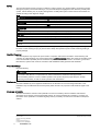
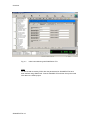
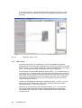
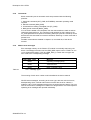
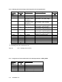
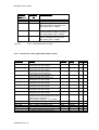
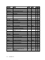
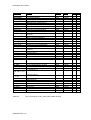
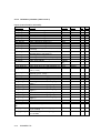
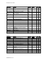
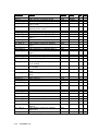
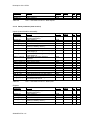
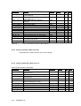
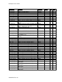
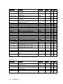
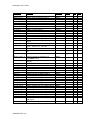
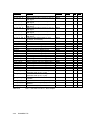
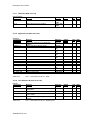
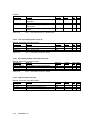
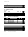
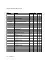
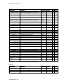
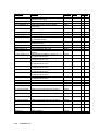
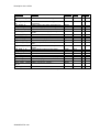
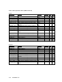
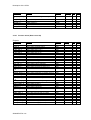
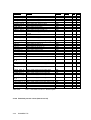
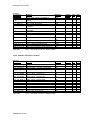
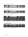
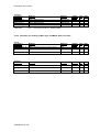
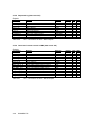
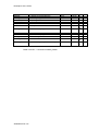
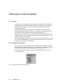
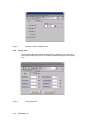
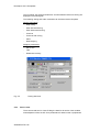
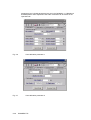
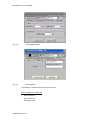
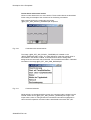


![VPS-715MU/715OU取扱説明書[PDF:4MB]](http://vs1.manualzilla.com/store/data/006600437_2-5b6f2b2d2af3c664fc426c123d7d6674-150x150.png)
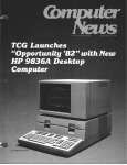


![HVS-TALOC/TALR 取扱説明書[PDF:992.4KB]](http://vs1.manualzilla.com/store/data/006672802_2-7e521979e0d7d78962e75db88f9173f3-150x150.png)