1
USER'S GUIDE
FOREWORD
CONTENTS
LAPCOM VX-2000 is a system that effectively supports engine and chassis setup for racing
machines. It provides all the desired data such as lap times, speed, engine RPM, G-force, steering,
throttle, temperature, pressure, voltage, and course mapping. Most of this data can be monitored
on a display by the driver, and logged into the control unit for up to 90 minutes.
*Lite and Basic can log data for up to 20 minutes.
For users who do not have a PC, the stored data, graphs, and course map can be printed with the
optional handy printer.
LAPCOM VX-2000 enables PC users to run simulations and analyze the data using our software,
Lapcom Terminal and Lapcom Analysis for Windows 95/98/NT.
For more advanced requirements, LAPCOM VX-2000 Hyper Pro Plus is for using the telemetry
system with a cellular phone, data transceiver or portable satellite phone (based on the Hayes AT
command).
For your safety, observe the following.
Warning Icons
Warning
Ignoring this may result in death or serious injury.
Caution
Ignoring this may result in injury or physical damage.
Alert
Ignoring this may result in the disruption or suspension of function.
Other Icons
This indicates an action that is not recommended. The proscribed action is shown
inside the icon or the icon is placed next to a diagram or sentence. The example at left
says, "Do not disassemble".
This indicates a mandatory action. The mandatory action is shown inside the icon or
the icon is placed next to a diagram or sentence. The example at left shows that a user
must remove the plug from the power outlet.
This indicates an action that should be performed. The necessary action is shown
inside the icon or the icon is placed next to a diagram or sentence.
Attention
1.
2.
3.
4.
Copying all or part of this manual without permission is strictly prohibited.
The contents of this manual may be modified without prior notice.
If you discover any errors, omissions, or any part that is unclear, we would appreciate your advising us.
Percul Co. accepts no liability or responsibility for any outcomes resulting from user operation, equipment failure,
incorrect operation, or external factors.
5. The warranty is voided if any of these products is disassembled or modified without permission.
: Windows 95/98/NT are registered trademarks of Microsoft Corporation.
: Hayes is a registered trademark of Hayes Micro Computer Products Inc.
2
CONTENTS
Read Before Use
How to Measure Segment Data by Dividing the
Course into Segments of Equal Distance ......44
How to Measure Segment Data by Dividing the
Course between Straights and Corners .........46
How to Measure Data within a Distance of 0
to 400m ..........................................................49
How to Measure Data for Speeds from 0 to
100kph ...........................................................50
How to Confirm, Delete, and Reset Data .......51
How to Print Data ...........................................53
Instructions for Use ..........................................4
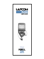
LAPCOM
Products at a Glance ....................................... 5
Parts and Installation ....................................... 7
LAPCOM Parts and Connectors ...................7
Charging with the AC Adapter ...................... 9
Installing the Display and Control Unit ........10
Installing the Optical Sensor .......................11
Installing the Pulse Lead for RPM .............. 12
Installing the Wheel Speed Sensor .............13
Pressure Sensor (Optional) ........................ 14
Temperature Sensor (Optional) .................. 14
Lambda Sensor Module (Optional) .............16
Displacement Sensors (Optional) ...............17
How to Set Parameters ..................................18
Basic Operation .......................................... 18
1 . How to Set the Backlight ....................... 19
2 . How to Enter the Speed Pulse Length ...20
3 . How to Set the Unit of Speed, kph or mph ...21
4 . How to Set the REV Position ................. 22
5 . How to Set the Shift Lamp .....................23
6 . How to Set Red Line and Full Scale ...... 24
7 . Selection of the Pressure Sensor .......... 25
8 . How to Set the Alarm for a Pressure
Drop .......................................................26
9 . How to Set the Alarm for a Temperature
Increase 1 ..............................................27
10. How to Set the Alarm for a Temperature
Increase 2 ..............................................28
11. Selection of Vehicle ................................29
12. How to Set the Air/Fuel Ratio ................ 30
13. How to Set the Data Transmission Rate
and Baud Rate ...................................... 31
14. Selection of Print Form .......................... 32
15. Transmitter Channel and Measurement
Mode ......................................................33
16. How to Set Lateral G ............................. 34
17. How to Record the Measurement
Pattern ................................................... 36
18. How to Set the Auto-off Timer ............... 38
19. Calibration of the Steering Movement ... 39
20. Calibration of the Throttle Position .........39
How to Set the Calendar and Time ................40
Basic Use .......................................................41
How to Measure Segment Data with
Transmitters ................................................... 42
Lapcom Terminal
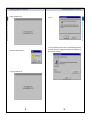
Installing Lapcom Terminal ............................ 55
Installing for Windows 98 ............................55
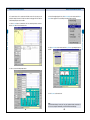
Data Communication ..................................... 61
Connecting to a PC by Cable ..................... 61
Connecting to a PC by Radio Modem ........ 65
Connecting to a PC by a Mobile Communication
Adapter/Modem such as a Cellular Phone ........69
Data Analysis and Simulation ........................73
How to Download the Data .........................73
How to Analyze the Data ............................ 75
Editing and Recording of Course Data .......... 78
How to Edit Course Data ............................ 78
How to Record Course Data into LAPCOM ... 81
Telemetry ....................................................... 84
Transmitter
Products at a Glance ..................................... 87
Parts .............................................................. 87
Charging with the AC Adapter ....................... 88
Selection of the Transmitting Code ................ 88
Installing ........................................................ 89
Printer
Products at a Glance ..................................... 90
Parts .............................................................. 90
Operating Panel .............................................91
Connecting the AC Adapter ........................... 92
Charging ........................................................ 92
How to Set the Paper .....................................93
How to Set the Dip Switches ......................... 94
3
CONTENTS
FOREWORD
Thank you very much for purchasing LAPCOM and its related products.
Instructions for Use
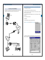
Products at a Glance
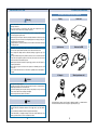
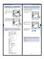
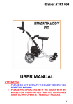
LAPCOM VX-2000 Standard System Components
Warning
Display
Control unit
Optical sensor
Pulse lead for RPM
AC adapter
Wheel speed sensor unit
If anything unusual emanates from the device such as smoke or a strange smell, immediately
remove the plug from the power outlet.
Remove the plug from the power outlet before conducting maintenance on this device. Leaving
it plugged in could cause an electric shock. Regularly wipe dust from the plug. Leaving it for
any length of time could result in fire.
During thunderstorms, stop using the device, remove all cables from the device and the plug
from the power outlet.
This device is not waterproof. If it gets wet it could cause a fire or an electric shock.
Do not touch the power outlet with wet hands, as this could cause an electric shock.
Do not modify the AC adapter, and do not bend, twist, damage, or apply heat to any of the
cables.
Use only the indicated voltage. Doing otherwise could cause a fire or an electric shock. When
using other electric appliances together from the same power outlet, ensure that the total
electric current does not exceed the circuit limit.
When using this device with an external DC power supply, connect it to the 12VDC power of a
negatively earthed vehicle.
Do not switch on the power to this device in the presence of inflammable gas as this could
cause a fire.
Do not use this device where the use of such devices is prohibited such as inside airplanes or
hospitals.
Caution
Use only the AC adapter supplied
Correctly insert the plug into the power outlet. Any metal that comes into contact with the AC
adapter plug could cause a fire or an electric shock.
Pull the AC adapter plug from the power outlet by the body. Pulling it out by the cord could
cause a fire, an electric shock, or damage to the adapter.
Before using these devices, read the User's Manual.
Alert
LAPCOM VX-2000's software, Lapcom Terminal for Windows 95/98/NT is not included with this
unit. Please download it from Percul's home page at <http://www.percul.co.jp>.
During operation, any cables that come loose or any connections that become unstable through
vibration could cause a malfunction of this device. Do not apply stress to any of the connector
joints.
Do not exceed the prescribed time limit when charging the internal battery.
If the internal battery is completely discharged, it could cause extreme deterioration of the
battery's performance and loss of all the stored data in the device.
4
5
Products at a Glance
Instructions for Use
Do not disassemble or modify this device. Doing so could cause a fire, an electric shock, or
damage to the device.
Do not use this device on any vehicle that is NOT 12VDC with a negative earth. Doing so
could cause a fire, an electric shock, or damage to the device.
Products at a Glance
Parts and Installation
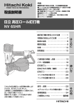
Transmitter TX-100 Standard System Components
Transmitter
LAPCOM Parts and Connectors
Bracket
AC adapter
2
3
4
5
6
7
8
10 11 12 13
The color cards and hanger are optional.
15 16 17
Back
1
9
8pin EXT.Cable 1.5m
Handy Printer DPU-414
Printer
Thermal paper
External battery
connection cable
18
20
SHIFT
19
MODE
SET
21
CLEAR
22
Display
RED
DC input conversion cable
Display mount
The printer cable is optional (0581-02 Com port printer cable). The AC adapter is not included with
this unit. It is possible to use the AC adapter included with the VX-2000 or TX-100 unit.
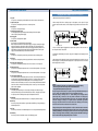
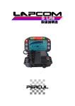
1. Power lamp
This lamp lights up when the device is on.
2. Print switch
Use this switch to print the stored data with the optional handy printer.
Position 1 is for printing graphic data and position 2 for numerical data.
3. Com port
This port is for connecting to the serial port of a PC, data transferring modems/adapters, or the
optional handy printer.
4. REV jack
This jack is for connecting the pulse lead to measure engine RPM.
5. Speed jack
This jack is for connecting the wheel speed sensor to measure wheel speed.
6
7
Parts and Installation
Products at a Glance
Front
14
Parts and Installation
Parts and Installation
Charging with the AC Adapter
(Lite does not have a 12VDC jack.)
6. A/F jack
This jack is for connecting the optional lambda sensor module to measure the air/fuel ratio.
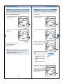
1. Make sure that the power switch is turned OFF.
7. Optical sensor jack
This jack is for connecting the optical sensor to measure lap times.
2. When running LAPCOM on a tabletop using the AC adapter, use the optional DC input
conversion cable. One end connects to the AC adapter's DC plug and the other end to the 12VDC
jack.
8. Display jack
This jack is for connecting the display.
AC adapter
DC input conversion cable
9. Quick Charging monitor lamp
This lamp lights up when quick charging the internal battery with the AC adapter.
It does not light up during trickle charging.
11.Power switch
Use this switch to run LAPCOM with the internal battery.
When running LAPCOM with an external power supply (12V+- 4V), the external power supply
takes priority regardless of whether this switch is turned ON or OFF. If the external power
supply is disconnected and the switch is ON, the power supply automatically switches to the
internal battery to keep LAPCOM running. When running LAPCOM with an external power
supply, it is recommended that the power switch be turned OFF.
12.THR jack
This jack is for connecting the optional linear potentiometer to measure throttle position.
13.STR jack
This jack is for connecting the optional rotary potentiometer to measure steering movement.
14.Pressure jack (excluding Lite)
This jack is for connecting the optional pressure sensor to measure oil or fuel pressure.
Power switch, OFF
3. As soon as the AC adapter is plugged into the power outlet, the power of the control unit is on
even if the power switch is turned OFF.
4. If charging the internal battery, insert the DC plug of the AC adapter into the charging jack of the
control unit.
5. After plugging the AC adapter into the power outlet, quick charging finishes in about 2 hours, the
monitor lamp goes out, and regular trickle charging starts. To fully charge the control unit continue
trickle charging for about 10 hours.
15.Temperature 1 jack
This jack is for connecting the temperature sensor to measure the temperature of various parts.
AC adapter
16.Temperature 2 jack
This jack is for connecting the temperature sensor to measure the temperature of various parts.
17.12VDC jack (excluding Lite)
For use with the optional external battery cable (red +, black -) when running LAPCOM from an
in-vehicle battery, for backlighting the display at night races, or for directly running a lambda
sensor. When connecting the external battery cable to an in-vehicle battery, remove the
terminal from the in-vehicle battery to avoid a short circuit. If linking LAPCOM with the ON/OFF
switch of the vehicle, connect the external battery cable to an accessory such as the cigarette
lighter or audio equipment.
18.Information Lamps
To help with gear change timing, four of these lamps (shift lamps) flash when the engine
reaches the RPM set by the user. If the RPM reaches the red line, 6 lamps light up. The lamps
also light up as alarms to indicate pressure drops and temperature increases.
19. MODE key
Use this key to display the stored data after races or to change the parameter settings.
20.SHIFT key
Use this key to display the stored data or together with the MODE key to change the display to
the default-input screen.
21.SET key
Use this key to select values on the default-input screen or to set the potentiometer displacement.
22.CLEAR key
Use this key to end each mode and to return to the initial display screen.
8
Caution
Observe the following instructions to avoid deterioration of the internal battery.
Do not charge the control unit for longer than the recommended time.
Charge within the temperature range of 5 to 40°C.
A fully charged internal battery is capable of running LAPCOM continuously for
up to 11 hours. (Lite and Basic can be run for a maximum of 4 hours)
When the battery is running low, a "V" starts flashing on the display and the
power lamp will go out due to the auto power off function even though the
power switch is still turned ON. When that occurs, turn the power switch OFF
and start charging the battery. If the power switch is turned ON again before
charging, auto power off will not function and the total discharge of the battery
will cause the loss of all stored data in the control unit.
Charge the battery before first using this device or if it has not been used for some time.
Quick charging may start after some trickle charging. This is not an error. If quick charging
immediately followed by trickle charging occurs over and over even though the internal
battery is not charged, activate the battery by turning the power switch ON to discharge it
after a 15-hour trickle charge. Repeat this process 2 or 3 times.
9
Parts and Installation
Parts and Installation
10.Charging jack
This jack is for connecting the AC adapter.
Parts and Installation
Parts and Installation
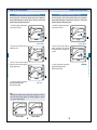
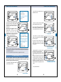
Installing the Display and Control Unit
Installing the Optical Sensor
1. Place the display in the optional display mount.
2. Install the display mount on the steering wheel or the instrument panel.
Display
3. An optional bracket is required to install the control unit.
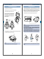
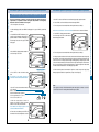
1. Install the optical sensor by drilling a 16φ sized hole in the desired place, such as on the body
cowling, so that infrared rays from the transmitter strike the front of the optical sensor lens. If
installing the sensor on a metallic part of the body such as the roll bar, avoid the effects of noise by
insulating the sensor from the car body with the resinous plate supplied. Do not lay the cable close
to a spark plug or ignition device, and do not bind the cable together with the pulse lead.
2. Insert the optical sensor connector into the optical sensor jack of the control unit.
4. The control unit includes a sensor that detects lateral G
(excluding Lite). Take note of the left and right orientation of
the unit when installing it in vehicles. (For bikes, install the
custom-made unit horizontally as well as taking note of the
left and right orientation.)
Optical sensor
Display mount
5. Use the supplied bolts (M6 x 10) to install the control unit on the bracket. Using bolts longer than
the ones supplied will damage the inside of the control unit.
Bracket
Attention
Lap times will not be recorded if strong sunlight shines on the optical sensor, especially
from the morning or setting sun.
If that is the case, move the transmitter to a spot where the optical sensor will not be
affected by sunlight, or wind about 50mm of masking tape or dark paper around the
outside of the sensor's screw to block the sunlight.
For touring cars, installing the sensor inside the car in the shade of the car roof is
effective. For formula cars or bikes, drilling an 8 to 10φ sized hole in the cowl and
installing the sensor about 15 to 20mm inside the surface of the cowl is recommended.
cowl
infrared
ray
M6x10 (MAX)
Attention
When it rains take measures to ensure the control unit does not get wet.
10
15~20mm
Regularly check the sensor's lens for oil or dust. Clean the lens with a cotton swab as
needed.
11
Parts and Installation
Parts and Installation
Be careful of
the direction.
Parts and Installation
Parts and Installation
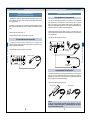
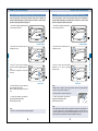
Installing the Pulse Lead for RPM
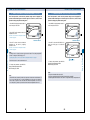
Installing the Wheel Speed Sensor
1. For Kart engines, replace the spark plug cap with a noise-suppressing product (NGK LB05EMH
or equivalent) or use a resistor spark plug.
1. Arrange the supplied magnet triggers on the axle or wheel. Usually 4 to 10 magnets are used.
The speed pulse length (outer circumference of tire / number of magnets) should be 100mm to
999mm. Determine the number of magnets to set the speed pulse length in this range.
2. To measure the RPM of multi-cylinder engines, clip the lead to where RPM is measured such as
where all the plug leads are gathered or the ignition coil lead.
2. Affix the magnets with tape.
Mounting the magnets on the sprocket or wheel by drilling holes may reduce their strength.
3. Insert the pulse lead connector into the REV jack of the control unit.
Magnet trigger
Parts and Installation
4. Inser t the wheel speed sensor connector into
the speed sensor jack of the control unit.
Attention
If the pulse lead cannot be clipped to vehicles in which the ignition coil or spark plug
leads are not exposed, enter an ECU (Engine Control Unit) pulse signal in LAPCOM. If the
signal voltage is 12V or under, make the connection with an optional RPM amp.
The RPM pulse lead has not been soldered to the clip to help dampen large engine
ignition pulses that may enter the microcomputer of the control unit from the RPM pulse
lead. If there is any damage that needs repair, ensure there is no electrical contact
between the cable and clip.
Wheel speed sensor
Wheel speed sensor
Magnet trigger
Attention
During installation, do not subject the upper resinous part of the sensor to any stress by
pinching or wrenching it with a tool.
12
13
Parts and Installation
Pulse lead for RPM
3. Install the wheel speed sensor so that the sensing
surface is close to the magnets but not touching them.
Any contact would cause damage to the sensor. The
distance between the sensing surface and the magnets
depends on the installation setup, but a gap of 5mm is
recommended.
Parts and Installation
Parts and Installation
Pressure Sensor (Optional): Max 20kg/cm2
Non-contact sensor for surface temperature with a guarantee of accuracy from 20°C to 100°C
(Lite does not have a pressure sensor jack.)
1. The sensor screw has a standard size of 1/8 PT. Install the sensor at the desired place or on the
line ensuring there is no loss of pressure.
2. Insert the pressure sensor connector into the pressure sensor jack of the control unit.
Pressure sensor
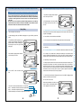
1. The non-contact sensor measures temperature based on the thermal energy radiated from a
circular area whose diameter is half the distance from the surface of the object being measured to
the sensor's lens. For example, if the distance from a tire's surface to the sensor's lens is 100mm,
the sensor measures the thermal energy radiated from a circular area with a diameter of 50mm
centered on the axis of the lens, and converts it to a temperature reading. Ensure that the circular
area does not run off the surface of the object being measured.
Tires kick up stones and dust by centrifugal force when rotating at high speed. To prevent damage
to the sensor or defective measurement, install the sensor at an oblique angle away from the
direction of the centrifugal force.
2. If operating continuously for hours, direct the airflow through a hose and onto the lens surface.
This prevents dust collecting on the lens.
3. Insert the temperature sensor connector into the TMP 1 or TMP 2 jack of the control unit.
Sensor for intake/exhaust air temperature - 0°C to 1000°C
1. The sensor's screw has a standard size of 1/8 PT. Install the sensor so that the sensing head is
seated in the flow of gas to be measured.
2. Insert the temperature sensor connector into the TMP 1 or TMP 2 jack of the control unit.
3. Set parameter number 9 or 10, "Alarm for a Temperature Increase". Please see page 27 or 28.
Temperature Sensor (Optional)
Sensor for water/oil temperature ranging from 0°C to 200°C
Sensor for intake/exhaust
air temperature
1. The sensor's screw has a standard size of 1/8 PT. Install the sensor at the desired place.
2. Insert the temperature sensor connector into the TMP 1 or TMP 2 jack of the control unit.
Sensor for water/oil
temperature
Attention
LAPCOM VX-2000 automatically switches between low temperature mode (0°C to 200°C)
and high temperature mode (201°C to 1000°C) depending on the value set for "Alarm for a
Temperature Increase". If the value set is 200°C or under, it operates in low temperature
mode in which case temperatures higher than 200°C cannot be measured. Likewise, if the
setting is 201°C or higher, it operates in high temperature mode and temperatures under
201°C cannot be measured.
14
15
Parts and Installation
Parts and Installation
Sensor for surface
temperature
Parts and Installation
Parts and Installation
Lambda Sensor Module (Optional)
Displacement Sensors (Optional)
(Lite does not support the Lambda Sensor module.)
2. Avoiding any hot sections in the back of the engine exhaust port where temperatures can reach
800°C or more, weld a nut (M18mm, pitch 1.5mm) or an adapter to the exhaust pipe to install the
sensor.
3. Fasten the sensor with a torque of 4.5kg - m
4. Insert the lambda sensor connector into the A/F jack of the control unit.
Parts and Installation
For a vehicle with an air/fuel ratio controller
Rotary potentiometer for steering movement
1. The sensor has a mechanical rotation angle from 0° for installation to 360° and an electrical
rotation angle from 20° to 340°. Although there is a mark near the center (180° ) for electrical
rotation, it is not necessary to note for installation whether the rotation is right-handed or lefthanded. Using a speed reduction mechanism, the sensor is capable of determining whether the
rotary direction is the same as or opposite to the steering rotary direction.
2. When installing, ensure that the rotation center of the sensor is in line with the center of the
steering movement angle and adjust the right and left displacement angle of the steering within
+-160° of electrical rotation.
3. Insert the sensor cable connector into the STR jack.
1. If a vehicle has an air/fuel ratio controller (TC-6000D of NTK Co.), it is possible to use the
controller by connecting the input terminal of an A/F cable (optional) to the output terminal of the
controller that has been connected with ECU.
2. Insert the A/F cable connector into the A/F jack of the control unit.
Rotary potentiometer
(Restricted)
Lambda sensor module
Rotary potentiometer
(Not restricted)
Linear potentiometer for throttle position
1. The maximum and minimum points can be freely set within the sensor stroke. If they exceed the
stroke, the sensor will be damaged. When installing, set the measuring object's mechanical
displacement (such as the amount of movement of throttle wire) to within the stroke range, and
allow some margin for the maximum and minimum points.
2. Insert the sensor cable connector into the THR jack.
Linear potentiometer
Linear potentiometer
Attention
If using the linear potentiometer to measure steering movement, or the rotary
potentiometer to measure throttle position or suspension displacement, read through
each instruction handbook for proper use.
16
17
Parts and Installation
1. The lambda sensor module cannot be run with LAPCOM's internal battery. Connect the control
unit to the external power supply (12V-15V). Total electric current consumption while running the
sensor is approximately 2A.
How to Set Parameters
How to Set Parameters
Basic Operation
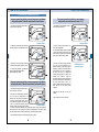
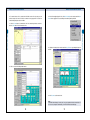
1. How to Set the Backlight (ILLUM)
Putting the control unit into parameter input mode using the display keys.
Default: OFF (Backlight is optional.)
After "Basic Operation", confirm that the parameter setting screen is displayed. The
parameter number should appear on the lower right of the screen. If not, return to "Basic
Operation" to display the parameter setting screen.
1. Turn on the power to the control unit.
2. Confirm the display's initial screen. READY
should appear. If not, press CLEAR to get the
initial screen.
1. Press MODE to display parameter number 1
on the lower right of the screen.
3. Press the Mode and SHIFT keys simultaneously
for 3 seconds to display the parameter setting
screen. The parameter number or calendar
should appear on the lower right of the screen.
Backlight: OFF
Parameter number 1
Parameter number
Note
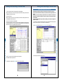
If the optional handy printer is connected to the control unit the current parameter data list can be
printed out by moving the print switch to position 2 for one second while the parameter setting
screen is displayed.
3. If setting other parameters, press MODE to
display the desired parameter number.
When finished, press CLEAR.
Note
The backlight is for running LAPCOM at night. Use of the external DC power supply (12V-15V) is
recommended. Using the backlight continuously with the internal battery will drastically shorten
its operating time.
If the display does not have the optional backlight, do not set the brightness to anything other
than the default, OFF (0).
18
19
How to Set Parameters
How to Set Parameters
2. Press SET to select the brightness of the
display's backlight: OFF (0), ON (1), ON (2), and
ON (3).
Avoid setting the brightness in a well-lit area.
How to Set Parameters
How to Set Parameters
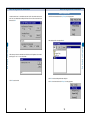
2. How to Enter the Speed Pulse Length
Default: 999mm
3. How to Set the Unit of Speed, kph or mph
After "Basic Operation", confirm that the parameter setting screen is displayed. The
parameter number should appear on the lower right of the screen. If not, return to "Basic
Operation" to display the parameter setting screen.
After "Basic Operation", confirm that the parameter setting screen is displayed. The
parameter number should appear on the lower right of the screen. If not, return to "Basic
Operation" to display the parameter setting screen.
1. Press MODE to display parameter number 2
on the lower right of the screen.
1. Press MODE to display parameter number 3
on the lower right of the screen.
Parameter number 2
Parameter number 3
2. Press SET to select the unit of speed: kph or
mph.
3. If setting other parameters, press MODE to
display the desired parameter number. When
finished, press CLEAR.
3. Press SET to select a value. Set the desired
pulse length (mm) by repeating operations 2 and
3.
4. If setting other parameters, press MODE to
display the desired parameter number.
When finished, press CLEAR.
20
Select a value.
21
How to Set Parameters
2. Press SHIFT until the numerical value to be
changed starts to flash.
How to Set Parameters
Default: kph
How to Set Parameters
How to Set Parameters
4. How to Set the REV Position
5. How to Set the Shift Lamp
Default: P: 2
After "Basic Operation", confirm that the parameter setting screen is displayed. The
parameter number should appear on the lower right of the screen. If not, return to "Basic
Operation" to display the parameter setting screen.
After "Basic Operation", confirm that the parameter setting screen is displayed. The
parameter number should appear on the lower right of the screen. If not, return to "Basic
Operation" to display the parameter setting screen.
1. Press MODE to display parameter number 4
on the lower right of the screen.
1. Press MODE to display parameter number 5
on the lower right of the screen.
Parameter number 5
Parameter number 4
2. Press SHIFT until the numerical value to be
changed starts to flash.
3. If setting other parameters, press MODE to
display the desired parameter number.
When finished, press CLEAR.
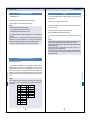
Select the REV position.
P:
1
4 strokes
P:
2
2 strokes
1 sylinder
4 strokes
2 sylinders
P:
3
4 strokes
3 sylinders
P:
4
2 strokes
2 sylinders
4 strokes
4 sylinders
2 strokes
3 sylinders
P:
6
4 strokes
P:
6 sylinders
8
4 strokes
8 sylinders
P : 10
4 strokes
10 sylinders
P : 12
4 strokes
12 sylinders
Note
The table may not accommodate certain vehicle types.
22
1 sylinder
How to Set Parameters
2. Press SET to select the desired REV position
according to the table below.
How to Set Parameters
Default: 16000rpm
3. Press SET to select a value. Set the desired
RPM, at which point the shift lamps flash to
advise of gear change timing, by repeating
operations 2 and 3.
Select a value.
4. If setting other parameters, press MODE to
display the desired parameter number.
When finished, press CLEAR.
Note
The RPM set for the shift lamps should be lower than the maximum value of the displayed graph.
23
How to Set Parameters
How to Set Parameters
4. How to Set Red Line and Full Scale
Default: 20000rpm
7. Selection of the Pressure Sensor
After "Basic Operation", confirm that the parameter setting screen is displayed. The
parameter number should appear on the lower right of the screen. If not, return to "Basic
Operation" to display the parameter setting screen.
After "Basic Operation", confirm that the parameter setting screen is displayed. The
parameter number should appear on the lower right of the screen. If not, return to "Basic
Operation" to display the parameter setting screen.
1. Press MODE to display parameter number 6
on the lower right of the screen.
1. Press MODE to display parameter number 7
on the lower right of the screen.
Parameter number 7
Parameter number 6
3. Press SET to select a value. Set the desired
RPM, at which point the shift lamps light up, by
repeating operations 2 and 3.
4. If setting other parameters, press MODE to
display the desired parameter number.
When finished, press CLEAR.
3. If setting other parameters, press MODE to
display the desired parameter number.
When finished, press CLEAR.
Select a value.
Note
LAPCOM VX-2000 automatically changes the display's graph scale depending on the RPM set
for the red line. Under 11000rpm, a graph from 0 to 11000rpm is displayed. For 11000rpm or
over, a graph to 21000rpm is displayed.
Full scale: 11000rpm
Full scale: 21000rpm
24
25
How to Set Parameters
2. Press SET to select a value from 20kg f/cm2,
50kgf/cm2, and 100kgf/cm2, that corresponds to
the maximum rated value of the pressure sensor
to be used.
2. Press SHIFT until the numerical value to be
changed starts to flash.
How to Set Parameters
Default: 20kgf/cm2
How to Set Parameters
8. How to Set the Alarm for a Pressure Drop
How to Set Parameters
Default: 00.0kgf/cm2 (Lite does not have this function)
9. How to Set the Alarm for a Temperature Increase 1
After "Basic Operation", confirm that the parameter setting screen is displayed. The
parameter number should appear on the lower right of the screen. If not, return to "Basic
Operation" to display the parameter setting screen.
After "Basic Operation", confirm that the parameter setting screen is displayed. The
parameter number should appear on the lower right of the screen. If not, return to "Basic
Operation" to display the parameter setting screen.
1. Press MODE to display parameter number 8
on the lower right of the screen.
1. Press MODE to display parameter number 9
on the lower right of the screen.
Parameter number 9
2. Press SHIFT until the numerical value to be
changed starts to flash.
2. Press SHIFT until the numerical value to be
changed starts to flash.
3. Press SET to select a value. Set the desired
pressure for the alarm by repeating operations 2
and 3.
Set the value to 00.0kgf/cm2 to turn the alarm
function off.
3. Press SET to select a value. Set the desired
temperature for the alarm by repeating
operations 2 and 3.
Select a value.
4. The lamps light up if the pressure falls below
the set value during engine rotation.
When the engine stops rotating, the alarm will
stop.
How to Set Parameters
Parameter number 8
How to Set Parameters
Default: 200°C
Select a value.
Note
If setting to 1000°C or higher, first select a value lower than 1000°C. Then, after pressing SHIFT
to make "°C" flash, press SET to display "+103".
Set the value to 000°Cto turn the alarm function off.
5. If setting other parameters, press MODE to
display the desired parameter number.
When finished, press CLEAR.
Note
For Lite, do not set any value other than the default, 00.0kgf/cm2.
26
4. If setting other parameters, press MODE to
display the desired parameter number.
When finished, press CLEAR.
Note
LAPCOM VX-2000 automatically switches the temperature measurement mode between low
(0°C to 200°C) and high (201°C to 1000°C) depending on the value set for the alarm. For 200°C
or under, it operates in low mode and cannot measure temperatures over 200°C. For 201°C and
higher, it operates in high mode and cannot measure temperatures under 201°C.
27
How to Set Parameters
How to Set Parameters
10. How to Set the Alarm for a Temperature Increase 2
Default: 200°C
11. Selection of Vehicle
Default: CAR (Lite does not have this function.)
After "Basic Operation", confirm that the parameter setting screen is displayed. The
parameter number should appear on the lower right of the screen. If not, return to "Basic
Operation" to display the parameter setting screen.
After "Basic Operation", confirm that the parameter setting screen is displayed. The
parameter number should appear on the lower right of the screen. If not, return to "Basic
Operation" to display the parameter setting screen.
1. Press MODE to display parameter number 10
on the lower right of the screen.
1. Press MODE to display parameter number 11
on the lower right of the screen.
2. Press SHIFT until the numerical value to be
changed starts to flash.
See "How to Set the Alarm for a Temperature Increase
1", number 2 on page 27.
Parameter number 11
Parameter number 10
3. Press SET to select a value. Set the desired
temperature for the alarm by repeating
operations 2 and 3.
2. Press SET to select from CAR, BIKE, or N, to
match the vehicle type to be loaded into
LAPCOM.
Note
If setting to 1000°C or higher, first select a value lower than 1000°C. Then, after pressing SHIFT
to make "°C" flash, press SET to display "+103".
See (Note) after operation 3 of "How to Set the Alarm for a Temperature Increase 1" on page 27.
Set the value to 000°C to turn the alarm function off.
4. If setting other parameters, press MODE to
display the desired parameter number.
When finished, press CLEAR.
Note
LAPCOM VX-2000 automatically switches the temperature measurement mode between low
(0°C to 200°C) and high (201°C to 1000°C) depending on the value set for the alarm. For
200°Cor under, it operates in low mode and cannot measure temperatures over 200°C. For
201°C and higher, it operates in high mode and cannot measure temperatures under 201°C.
28
3. If setting other parameters, press MODE to
display the desired parameter number.
When finished, press CLEAR.
Note
If using a four-wheeled vehicle, select CAR.
If using a two-wheeled vehicle with LAPCOM VX-2000 for bike, select BIKE.
If measuring data within a distance of 0m to 400m or for speeds from 0kph to 100kph, select N.
29
How to Set Parameters
How to Set Parameters
See "How to Set the Alarm for a Temperature Increase
1", number 3 on page 27.
How to Set Parameters
12. How to Set the Air/Fuel Ratio
How to Set Parameters
Default: 1.00
Default: S/9600bps
After "Basic Operation", confirm that the parameter setting screen is displayed. The
parameter number should appear on the lower right of the screen. If not, return to "Basic
Operation" to display the parameter setting screen.
After "Basic Operation", confirm that the parameter setting screen is displayed. The
parameter number should appear on the lower right of the screen. If not, return to "Basic
Operation" to display the parameter setting screen.
1. Press MODE to display parameter number 12
on the lower right of the screen.
1. Press MODE to display parameter number 13
on the lower right of the screen.
3. Press SET to select a value. Set the desired
theoretical value of the air/fuel ratio by repeating
operations 2 and 3.
4. If setting other parameters, press MODE to
display the desired parameter number.
When finished, press CLEAR.
2. Press SET to select the data transmission
rate: S, M or L, to match the communication
speed (baud rate) of the line to be used.
Only the VX-2000 Hyper Pro and Hyper Pro Plus
have this function.
Parameter number 13
How to Set Parameters
Parameter number 12
2. Press SHIFT until the numerical value to be
changed starts to flash.
How to Set Parameters
13. How to Set the Data Transmission Rate and Baud Rate
3. When changing the baud rate, press SHIFT to
display the currently set baud rate, which
appears on the lower left of the screen.
Select a value.
Note
In our tests, we used fuel with a theoretical value of 14.57 for the air/fuel ratio.
If setting the value to 1.00 (default), the air/fuel ratio is indicated by l.
If setting the value to 00.00, the air/fuel ratio is indicated as a concentration of oxygen in the
exhaust gas as a %.
Current baud rate: 9600bps
4. Press SET to select the baud rate: 12
(1200bps) to 115 (115200bps) to match the
communication speed (baud rate) of the device
to be used.
5. If setting other parameters, press MODE to
display the desired parameter number.
When finished, press CLEAR.
Note
The data transmission rate is the data transmission cycle when LAPCOM sends data to a PC via
the telemetry system over communication facilities such as radio or cellular phones. If setting S
(default), a communication speed of 9600bps or more is required. If using a general radio
modem for telemetry, the transmission rate of M or L may be necessary for normal operation.
30
31
How to Set Parameters
How to Set Parameters
Default: 0
15. Transmitter Channel and Measurement Mode
After "Basic Operation", confirm that the parameter setting screen is displayed. The
parameter number should appear on the lower right of the screen. If not, return to "Basic
Operation" to display the parameter setting screen.
After "Basic Operation", confirm that the parameter setting screen is displayed. The parameter
number should appear on the lower right of the screen. If not, return to "Basic Operation" to display
the parameter setting screen.
1. Press MODE to display parameter number 14
on the lower right of the screen.
1. Press MODE to display parameter number 15
on the lower right of the screen.
Parameter number 14
How to Set Parameters
2. Press SET to select the desired print form:
PRINT 0 to PRINT 6.
3. If setting other parameters, press MODE to
display the desired parameter number.
When finished, press CLEAR.
Note
If PRINT 0 (default) is selected, all the forms from PRINT 1 to PRINT 6 can be generated.
For the details of each print form, see page 54.
If segment times are not to be measured, form 2 is not generated.
Parameter number 15
2. Press SHIFT to make the channel setting
flash.
Pressing the SET key toggles through the
channel settings in the following order: 1, 2, 3, 4,
5, 6, 7, 8, 9, 0, A, B, C, D, E, F, -, H, and L.
3. Select the desired channel setting to match the
measurement conditions and the transmitter
channel.
- : Enables measurement of time by switches
or signals from various sensors instead of
using a transmitter.
H : Enables measurement of speed from 0kph
to 100kph.
L : Enables measurement of distance from 0m
to 400m.
4. Press SHIFT to start the channel setting of the
transmitters located in segments flashing. If
measuring segment time by using a transmitter in
each segment, press SET to select the desired
channel. If not measuring segment time, select "", and continue with step 5.
32
33
How to Set Parameters
14. Selection of Print Form (with Optional handy printer)
How to Set Parameters
How to Set Parameters
<When measuring segment times
with transmitters>
. Select the channel.
2. Press SHIFT until the numerical value to be
changed starts to flash.
<When measuring segment times
without transmitters>
. Select " - ".
3. Press SET to select a value. Set the desired
lateral g by repeating operations 2 and 3.
When creating and editing course data, the point
where the lateral g is generated beyond the set
value is deemed to be the start of the corner.
<When measuring segment times
by dividing the course into
segments of equal distance>
. Select a number or letter from 1
to F.
<When measuring segment times
by dividing the course between
straights and corners, and course
data is to be recorded in
LAPCOM>
. Select " - ".
See pages 46 and 82.
Note
When creating and recording course data that is divided into straights and corners by lateral g,
refer to page 46 of this manual for how to edit the course data using the LAPCOM VX-2000 and
the handy printer without a PC.
If a PC is to be used with the Lapcom Terminal, refer to page 82 of this manual.
16. How to Set Lateral G.
Default: 0.5G
After "Basic Operation", confirm that the parameter setting screen is displayed. The
parameter number should appear on the lower right of the screen. If not, return to "Basic
Operation" to display the parameter setting screen.
1. Press MODE to display parameter number 16
on the lower right of the screen.
Select a value.
4. Press SHIFT for 3 seconds to display the
setting of the other lateral g that is for detecting
the corner's end point.
Press SHIFT until the numerical value to be
changed starts to flash. Press SET to select a
value. Set the desired lateral g by repeating
those operations.
Lateral g that is for detecting
the corner's end point.
5. By pressing SHIFT for 3 seconds, the value on
the lower left of the screen starts flashing.
Set the distance by pressing SHIFT to start the
number flashing and then press SET to select a
value.
This value is the distance from the corner's start
point. Within this distance the reduction of lateral
g is ignored and the corner's end point is not
recognized. It is set to have many small corners
recognized as a big segment. It can be set up to
999m. If this function is not required set the value
to 000m.
6. Go to parameter number 17.
Parameter number 16
34
35
Press SHIFT key to start flashing.
Press SET key to select a value.
How to Set Parameters
How to Set Parameters
5. Press SHIFT to start the number of segments
value flashing. Setting this number enables the
measurement of time for each segment for a
course that has been divided into segments of
equal distance.
Press SET to select a number or letter as the
desired number of segments. A is for 10
segments, B for 11, C for 12, D for 13, E for 14,
and F for 15. If the course is not to be
segmented, select 1 and go to the setting of
parameter number 18. If segments has been set
(excluding 1), go to parameter number 17.
How to Set Parameters
How to Set Parameters
17. How to Record the Measurement Pattern
To measure segment time by dividing a course into segments of equal distance
with parameter number 15 when the course distance is known in advance.
1. Press MODE to display parameter number 17
on the lower right of the screen.
How to Set Parameters
Parameter number 17
Parameter number 17
2. To enter the course distance, press SHIFT until
the numerical value to be changed starts to flash.
2. Press SET to select a record number, 0 to 9,
for the measurement pattern.
The measurement patterns are data that include
a course map created from driving the course
and the positions of segment time measurement
points. Up to 10 patterns can be recorded.
3. Press SET to select a value. Enter the desired
course distance by repeating operations 2 and 3.
3. Drive the course. After passing the transmitter
for the first time, the measurement of the
distance and lateral g starts. After passing the
transmitter a second time, measurement finishes
and the distance of the course is displayed on
the screen. If the course is not being traced
accurately, through spinning or sliding off for
example, press CLEAR to cancel the
measurement and restart the measurement with
the next lap. After finishing the measurement of
the course correctly, return to the pit. It is
possible to repeat the measurement a number of
times until the trace has been correctly
completed.
4. If setting other parameters, press MODE to
display the desired parameter number.
When finished, press CLEAR.
Select a value.
To measure segment time by dividing a course into segments of equal distance
with parameter number 15 when the course distance is not known in advance.
1. Press MODE to display parameter number 17
on the lower right of the screen.
2. Drive the course. After passing the transmitter
for the first time, the measurement of the
distance starts. After passing the transmitter a
second time, measurement finishes and the
course distance is displayed on the screen. If the
course is not being traced accurately, through
Parameter number 17
spinning or sliding off for example, press CLEAR
to cancel the measurement and restart the measurement with the next lap. After finishing the
measurement of the course correctly, press CLEAR to record the distance. It is possible to repeat
the measurement a number of times until the distance is recorded by pressing CLEAR.
4. Edit the course data. See "16. How to Set
Lateral G."
5. Press CLEAR to record the course data.
3. Once the distance has been set, the measurement of time is possible.
36
37
Record number for the
measurement pattern
How to Set Parameters
1. Press MODE to display parameter number 17
on the lower right of the screen.
To measure segment time by dividing a course between
straights and corners with parameter number 15 ("-").
How to Set Parameters
18. How to Set the Auto-off Timer
19. Calibration of the Steering Movement
After "Basic Operation", confirm that the parameter setting screen is displayed. The
parameter number should appear on the lower right of the screen. If not, return to "Basic
Operation" to display the parameter setting screen.
After "Basic Operation", confirm that the parameter setting screen is displayed. The
parameter number should appear on the lower right of the screen. If not, return to "Basic
Operation" to display the parameter setting screen.
1. Press MODE to display parameter number 18
on the lower right of the screen.
1. Press MODE to display parameter number 19
on the lower right of the screen.
2. Press SHIFT to start the numerical value
flashing, then press SET to enter a value that
corresponds to the lap time. A value up to 9
minutes 50 seconds can be set. If the vehicle
does not pass through the measurement section
or does not complete a lap within the set time, it
will be deemed that the vehicle has slowed down
or stopped. Measurement is canceled and
logging stops. The default value is 0.00 (10
minutes).
2. Turn the steering wheel full lock to the left then
press SET.
3. Then turn the steering wheel full lock to the
right and press CLEAR to finish. If the calibration
is completed correctly, the indicator is displayed
on the screen.
Setting of time
Parameter number 18
Note
If only the time has been set (by setting speed to 000kph), the lap time in which the vehicle
enters the pit without passing the transmitter will be invalid and not recorded. Only lap time data
in which the vehicle passes the transmitter within the set time is valid.
When the vehicle enters the pit without passing the transmitter, it slows down dramatically and
stops for a certain period. In order to make this lap time data valid for recording set the speed
and time as follows:
3. Press SHIFT for 3 seconds to start the unit of
speed flashing.
Parameter number 19
SET key
CLEAR key
Note
If the sensor is not being using for steering movement, remove it from the control unit and make
the calibration. The indicator will disappear.
20. Calibration of the Throttle Position
After "Basic Operation", confirm that the parameter setting screen is displayed. The
parameter number should appear on the lower right of the screen. If not, return to "Basic
Operation" to display the parameter setting screen.
4. Press SHIFT again until the numerical value to
be changed starts to flash.
1. Press MODE to display parameter number 20
on the lower right of the screen.
5. Press SET to select a value. Set the desired
speed where logging stops or starts by repeating
operations 4 and 5.
2. Close the throttle then press SET.
3. Fully open the throttle and press CLEAR to
finish. If calibration is completed correctly, the
indicator is displayed on the screen.
6. Press SHIFT again for 3 seconds to start time
flashing.
Parameter number 20
Select a value.
Note
The speed set should be quite low (excluding 000 kph) compared with regular driving speed.
Setting of time together with speed avoids cessation of logging due to a temporary slow down
such as wheel lock during braking.
7. If setting other parameters, press MODE to
display the desired parameter number.
When finished, press CLEAR.
38
SET key
CLEAR key
Note
If the sensor is not being using for throttle position, remove it from the control unit and make the
calibration. The indicator will disappear.
39
How to Set Parameters
How to Set Parameters
How to Set Parameters
How to Set Parameters
Basic Use
How to Set the Calendar and Time
Basic Use
After "Basic Operation", confirm that the parameter setting screen is displayed. The
parameter number should appear on the lower right of the screen. If not, return to "Basic
Operation" to display the parameter setting screen.
LAPCOM stores data from each sensor based on lap time and wheel speed. Therefore, the
measurement of these is indispensable.
See "Parts and Installation" for installation of the sensors.
1. Press MODE to display the Calendar. It has
been assigned behind parameter number 20.
Year
Month
Getting Ready
1. Turn on the power to the control unit.
2. Press SHIFT until the numerical value to be
changed starts to flash.
2. Confirm the display's initial screen. READY should appear. If not, press CLEAR to get the initial
screen.
4. Press CLEAR to start the clock.
How to Set Parameters
Day
Time
3. Press Mode and SHIFT simultaneously for 3
seconds to get the parameter setting screen. The
parameter number or calendar should appear on
the lower right of the screen. If not, press CLEAR
and try again.
Basic Use
3. Press SET to enter a value. Set the desired
year, month, date, and time by repeating
operations 2 and 3.
4. Press MODE to display parameter number 15
on the lower right of the screen.
5. Press SHIFT to make the channel setting
flash.
For the details of this setting, see page 33,
"Transmitter Channel and Measurement Mode".
6. Press SET to select the transmitter channel, 0
to F, for lap times.
Select " - " if transmitters will not be used to measure segment times.
Select " 1" if the number of course segments is 1.
Parameter number 15
7. If setting other parameters like auto-off timer, press MODE to display the desired parameter
number.
When finished, press CLEAR.
8. Turn on the power to the transmitter. After confirming the channel, install the transmitter.
9. Start driving. As soon as the vehicle passes the transmitter, the monitor lamp lights up and time
measurement and data logging starts. LAPCOM can store data for up to 100 laps or a total of 90
minutes. Lite and Basic can store data for up to 20 minutes.
Note
After stopping the vehicle, LAPCOM automatically ends measuring after 10 minutes or the time
set in the auto-off timer. To manually end measurement, press CLEAR.
40
41
How to Measure Segment Time with Transmitters
How to Measure Segment Time with Transmitters
How to Measure Segment Time with Transmitters
1. Confirm READY appears on the left side of the
screen.
If it does not, press CLEAR to display it.
Getting Ready
How to Measure Segment Time with Transmitters
Confirmation of Data
1. Turn on the power to the control unit.
2. Confirm the display's initial screen. Time should appear on the lower right. If not, press CLEAR
to get the initial screen.
3. Press Mode and SHIFT simultaneously for 3
seconds to get the parameter setting screen. The
parameter number or calendar should appear on
the lower right of the screen. If not, press CLEAR
and try again.
2. Confirm the display's initial screen. Time
should appear on the lower right. If not, press
CLEAR to get the initial screen.
The displayed data includes lap time, wheel
speed, and temperature. Additionally, pressing
SET switches the displayed data to lateral g,
pressure, or RPM.
3. To display BEST LAP, press MODE for 3
seconds. The best lap is displayed with the
descriptor, BEST LAP.
4. Press MODE to display parameter number 15
on the lower right of the screen.
5. Press SHIFT key to make the channel setting
flash.
For the details of this setting, see page 33,
"Transmitter Channel and Measurement Mode".
6. Press SET to select the transmitter channel, 0
to F, for lap times.
Select the transmitter channel to measure segment times.
4. If confirming data for each segment, press
MODE and SHIFT simultaneously to start SEG
flashing.
Parameter number 15
7. If setting other parameters like auto-off timer, press MODE to display the desired parameter
number. When finished, press CLEAR.
8. Turn on the power to the transmitters. After confirming each channel, install the transmitters.
9. Start driving. When the vehicle passes the transmitters for lap times, 2 monitor lamps on the right
light up. When passing the transmitters for segment times, a lamp on the left lights up.
5. Press MODE to confirm the segment data in
order from the most recent lap to the oldest lap. Press SHIFT to reverse the order of laps.
6. If the MODE and SHIFT keys are again pressed simultaneously LAP and SEG flash making it
possible to confirm the same segment data for each lap.
7. To display BEST SEG, press MODE for 3 seconds. The best segment lap is displayed with the
descriptor, BEST.
8. To return to operation 2, press MODE and SHIFT simultaneously.
Note
After stopping the vehicle, LAPCOM automatically ends measuring after 10 minutes or the time
set in the auto-off timer. To manually end measurement, press CLEAR.
42
9. Press CLEAR to finish the confirmation of data.
43
How to Measure Segment Time with Transmitters
It is possible to accurately measure times by installing the maximum 14 transmitters in the
course segments.
How to Measure Segment Time by Dividing the Course into Segments of Equal Distance
How to Measure Segment Time by Dividing the Course into Segments of Equal Distance
Enter the course distance or measure it by driving. By setting the number of segments of
equal distance, it is possible to measure the segment data (maximum of 15 segments)
without the need for a transmitter in each segment.
1. Turn on the power to the control unit.
9. Press SET to select a value. Enter the course distance by repeating operations 8 and 9.
10. Press CLEAR to confirm the initial screen with the descriptor, READY.
11. Turn on the power to the transmitter. After confirming the channel, start driving.
2. Confirm the display's initial screen. READY should appear. If not, press CLEAR to get the initial
screen.
3. Press MODE and SHIFT simultaneously for 3
seconds to get the parameter setting screen. The
parameter number or calendar should appear on
the lower right of the screen. If not, press CLEAR
and try again.
4. Press MODE to display parameter number 15
on the lower right of the screen.
12. When the course distance is not known in advance, drive the course to measure its distance.
13. Press MODE to display parameter number17
on the lower right of the screen. Confirm that the
distance displayed is 00000m.
14. Turn on the power to the transmitter. After confirming the channel, start driving.
15. After passing the transmitter for the first time, measurement of the distance starts. After passing
the transmitter a second time, measurement finishes and the course distance is displayed on the
screen. If the course is not being traced accurately, including spinning or sliding off, press CLEAR
to cancel the measurement which will restart with the next lap. After finishing the measurement of
the course correctly, press CLEAR to record the distance. It is possible to repeat the measurement
a number of times until the distance is recorded by pressing CLEAR.
5. Press SHIFT to make the channel setting
flash.
For the details of this setting, see page 33,
"Transmitter Channel and Measurement Mode".
6. Press SET to select the transmitter channel, 0
to F, for lap times.
Select " - " if transmitters will not be used to measure segment data.
Select the desired number of segments.
A is for 10 segments, B for 11, C for 12,
D for 13, E for 14, and F for 15.
16. When the vehicle passes the transmitters for lap times 2 monitor lamps on the right light up.
When passing the transmitters for segment times, a lamp on the left lights up.
Note
After stopping the vehicle, LAPCOM automatically ends measuring after 10 minutes or the time
set in the auto-off timer. To manually end measurement, press CLEAR.
7. When the course distance is known in
advance, press MODE to display parameter
number 17 on the lower right of the screen.
For the details of this setting, see page 36, "How
to Record the Measurement Pattern".
8. To enter the course distance, press SHIFT until
the numerical value to be changed starts to flash.
44
45
How to Measure Segment Time by Dividing the Course into Segments of Equal Distance
How to Measure Segment Time by Dividing the Course into Segments of Equal Distance
How to Measure Segment Time by Dividing the Course into Segments of Equal Distance
How to Measure Segment Data by Dividing the Course between Straights and Corners
How to Measure Segment Data by Dividing the Course between Straights and Corners
Once the course has been driven to record the data and the edited course data (up to a
maximum of 10 courses) has been stored in LAPCOM, it can be called up at anytime making
it possible to measure segment data in the same course. Lite cannot obtain and edit the
course data.
Because the course data recorded by LAPCOM VX-2000 (excluding Lite) and edited by
Lapcom Terminal can be delivered to all models of LAPCOM VX, it is possible to measure
the data of all vehicles in the same team under the same condition
Getting Ready
7. Press MODE to display parameter number 17
on the lower right of the screen.
8. The flashing number is the course number for
recording the course data. Press SET to select
the value.
1. Turn on the power to the control unit.
9. If measuring data using course data that has previously been recorded, select that course
number. After the recorded course number is displayed, the course distance and the number of the
segments will be displayed.
2. Confirm the display's initial screen. READY should appear. If not, press CLEAR to get the initial
screen.
10. Press CLEAR to confirm the initial screen with READY.
3. Press MODE and SHIFT simultaneously for 3
seconds to get the parameter setting screen. The
parameter number or calendar should appear on
the lower right of the screen. If not, press CLEAR
and try again.
11. Turn on the power to the transmitter. After confirming the channel, install the transmitter.
Driving
12. Start driving.
13. If recording and editing new course data, first select the desired course number to be recorded.
4. Press MODE to display parameter number 15
on the lower right of the screen.
14. If selecting a course number that has already been recorded, the course distance and the
number of segments will be displayed. If this is the case, press SHIFT to make the number flash
and press SET to select the value. Set it to 00000m to delete the previously recorded course data.
15. Start driving to record the course data.
5. Press SHIFT to make the channel setting
flash.
16. After passing the transmitter for the first time, measurement of the distance and lateral g starts.
After passing the transmitter a second time, measurement finishes and the course distance is
displayed on the screen. If the course is not being traced accurately, including spinning or sliding
off, press CLEAR to cancel the measurement which will restart with the next lap. After finishing the
measurement of the course correctly, return to the pit. It is possible to repeat the measurement a
number of times until the trace has been correctly completed.
17. Confirm that the course distance is displayed on the screen. Press MODE to display parameter
number 16 on the lower right of the screen.
18. Press SET to select a value.
6. Press SET to select the transmitter channel, 0 to F, for lap times.
Select " - " if transmitters will not be used to measure segment data.
Select " - " if the number of segments will not be set.
LAPCOM automatically sets the number of segments based on run data.
46
When creating and editing course data, the point
where the lateral g is generated beyond the set
value is judged as the start of the corner.
47
How to Measure Segment Data by Dividing the Course between Straights and Corners
How to Measure Segment Data by Dividing the Course between Straights and Corners
How to Measure Segment Data by Dividing the Course between Straights and Corners
How to Measure Segment Data by Dividing the Course between Straights and Corners
How to Measure Data within a Distance of 0 to 400m
How to Measure Data within a Distance of 0 to 400m
Press SHIFT until the numerical value to be
changed starts to flash. Press SET to select a
value. Set the desired lateral g by repeating
those operations. The lateral g of the corner's
end point should be lower than the one for its
start point.
20. By pressing SHIFT for 3 seconds, the value
on the lower left of the screen starts flashing.
Set the distance by pressing SHIFT to start the
number flashing and then press SET to select a
value.
This value is the distance from the corner's start
point. Within this distance the reduction of lateral
g is ignored and the corner's end point is not
recognized. When making many small corners
recognized as a big segment, this value is set
based on the smallest corner's distance.
After the simple key operation described below, start driving to begin measurement.
LAPCOM automatically recognizes the start and 400m points, and measures lap time and
other data within that distance. It is possible to measure segment data by dividing the 400m
1. Replace the optical sensor with the optional push-button switch and turn on the power to the
control unit.
2. Confirm the display's initial screen. READY should appear. If not, press CLEAR to get the initial
screen.
3. Press MODE and SHIFT simultaneously for 3
seconds to get the parameter setting screen. The
parameter number or calendar should appear on
the lower right of the screen. If not, press CLEAR
and try again.
4. Press MODE to display parameter number 15
on the lower right of the screen.
21. After connecting the handy printer to the
control unit, move the print switch to position 1
for a second to print out the course layout and its
edited data.
22. Complete the desired course data by
repeating the printing and editing. Press CLEAR
to set the final data.
5. Press SHIFT to make the channel setting
flash.
23. After confirming the initial screen with
READY, start driving.
Note
After stopping the vehicle, LAPCOM automatically ends measuring after 10 minutes or the time
set in the auto-off timer. To manually end measurement, press CLEAR.
6. Press SET to select "L".
If transmitters are not being used for segment data, select " - ".
Otherwise, select the channel number.
If the number of segments is not being set, select " - ".
Otherwise, select the number of segments.
7. Press CLEAR to confirm the initial screen with READY.
8. If transmitters are being used for segment data, turn on the power to confirm the channel setting.
9. Move the vehicle to the start line and stop.
10. After confirming that the vehicle has completely stopped, press the push-button switch once.
11. As soon as the vehicle moves off, measurement starts. At the 400m point, measurement stops.
12. If continuing this measurement, repeat from operation 9.
48
49
How to Measure Data within a Distance of 0 to 400m
How to Measure Segment Data by Dividing the Course between Straights and Corners
19. Press SHIFT for 3 seconds to display the
setting of the other lateral g that is for detecting
the corner's end point.
How to Measure Data for Speeds from 0 to 100kph
How to Confirm, Delete and Reset Data
How to Measure Data for Speeds from 0 to 100kph
How to Confirm, Delete and Reset Data
After the simple key operation described below, start driving to begin measurement.
LAPCOM automatically recognizes the start point and the point where the speed reaches
100kph, and measures lap time and other data. It is possible to measure segment data by
dividing the 0 to 100kph section equally by speed or by setting up transmitters for segment
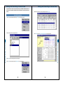
How to confirm the run data
1. Replace the optical sensor with the optional push-button switch and turn on the power to the
control unit.
2. Confirm the display's initial screen. READY should appear. If not, press CLEAR to get the initial
screen.
3. Press MODE and SHIFT simultaneously for 3
seconds to get the parameter setting screen. The
parameter number or calendar should appear on
the lower right of the screen. If not, press CLEAR
and try again.
1. Confirm READY appears on the left side of the screen.
If it does not, press CLEAR to display it.
2. Confirm the display's initial screen. Time
should appear on the lower right. If not, press
CLEAR to get the initial screen. The displayed
data includes lap time, wheel speed, and
temperature. Additionally, pressing SET switches
the displayed data to lateral g, pressure, or RPM.
4. If confirming data for each segment, press MODE and SHIFT simultaneously to start SEG
flashing.
4. kPress MODE to display parameter number 15
on the lower right of the screen.
5. Press MODE to confirm the segment data in order from the most recent lap to the oldest lap.
Press SHIFT to reverse the order of laps.
6. If the MODE and SHIFT keys are again pressed simultaneously LAP and SEG flash making it
possible to confirm the same segment data for each lap.
7. To display BEST SEG, press MODE for 3 seconds. The best segment lap is displayed with the
descriptor, BEST.
8. To return to operation 2, press MODE and SHIFT simultaneously.
5. Press SHIFT to make the channel setting
flash.
9. Press CLEAR to finish the confirmation of data.
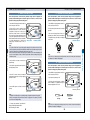
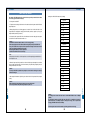
(Key operation to confirm segment data)
Initial screen (READY)
MODE+SHIFT
Press simultaneously.
6. Press SET to select "H".
If transmitters are not being using for segment data, select " - ".
Otherwise, select the channel number.
If the number of segments is not being set, select " - ".
Otherwise, select the number of segments.
Confirm each LAP. (LAP flashing)
SHIFT
MODE
MODE
Data scroll
Back
BEST(Press 3 seconds.)
SHIFT
Data scroll
MODE
Back
SHIFT
MODE
MODE
Data scroll
Back
BEST(Press 3 seconds.)
MODE+SHIFT
Press simultaneously.
Confirm each segment data. (SEG flashing)
7. Press CLEAR to confirm the initial screen with READY.
8. If transmitters are being used for segment data, turn on the power to confirm the channel setting.
9. Move the vehicle to the start line and stop.
10. After confirming that the vehicle has completely stopped, press the push-button switch once.
11. As soon as the vehicle moves off, measurement starts. When the vehicle reaches 100kph
measurement stops.
12. If continuing this measurement, repeat from operation 9.
50
Confirm the same
seg data.
(LAP+SEG flashing)
MODE+SHIFT
Press simultaneously.
MODE+SHIFT
Press simultaneously.
51
How to Confirm, Delete and Reset Data
How to Measure Data for Speeds from 0 to 100kph
3. To display BEST LAP, press MODE for 3 seconds. The best lap is displayed with the descriptor,
BEST LAP.
How to Confirm, Delete and Reset Data
Printing the Data
Printing the Data
How to delete data
How to print the data
1. Confirm READY appears on the left side of the screen.
If it does not, press CLEAR to display it.
1. Press CLEAR to display READY on the screen and move the print switch to position 2 for a
second to start printing the lap time data list.
2. Press MODE or CLEAR to display the lap data
to be deleted.
2. Press MODE or SHIFT to display the desired lap data. If the print switch is moved to position 1
for a second, graphic related forms including course layout will be printed, according to the setting
in parameter number 14.
If the switch is moved to position 2, the LAP-SEGMENT data list will be printed.
3. Press SET and CLEAR simultaneously for 3
seconds.
3. To cancel printing, press CLEAR.
4. Press CLEAR to finish deleting data.
Note
For the details of the print form setting, see page 33.
If segment times are not measured, form 2 is not printed.
Switch position 1 is for graphic data, 2 for various lists.
For the details of printer operation, see page 94.
How to delete all the data in a single block
1. Confirm READY appears on the left side of the screen.
If it does not, press CLEAR to display it.
2. Press SET and CLEAR simultaneously for 3 seconds.
1. Confirm READY appears on the left side of the screen.
If it does not, press CLEAR to display it.
2. Press MODE and CLEAR simultaneously. The
engine running time, trip meter, and odometer
display in turn.
3. If setting to 0, press MODE and CLEAR
simultaneously for 3 seconds.
Note
The only way to reset the odometer to 0 is to reset the control unit.
Printing the Data
How to Confirm, Delete and Reset Data
How to display and delete engine running time, trip meter, and odometer
How to reset the LAPCOM system to return it to the original factory settings
1. Confirm READY appears on the left side of the screen.
If it does not, press CLEAR to display it.
2. Press SHIFT, SET, and CLEAR simultaneously for 3 seconds and confirm that the whole screen
Note
If resetting the system, all the default settings and stored data will be lost.
52
53
Printing the Data
Installing Lapcom Terminal
. PRINT 4
These instructions assume that the hard disk is allocated as the C drive and the floppy disk
drive as the A drive. If your allocation is different, change the drive allocations in these
instructions to match yours.
When installing LAPCOM Terminal from CD-R, after double clicking the self-extracting
executable ZIP file, Installation automatically starts. Please omit the operation from 1 to 11.
1. Get Lapcom terminal's floppy disks #1, #2, and #3 ready.
2. After closing all other applications, click Start.
Click Control Panel in Setting.
. PRINT 2
. PRINT 5
3. Double click the Add/Remove Programs icon.
. PRINT 6
Printing the Data
. PRINT 3
54
55
Installing Lapcom Terminal
Installing for Windows 98
. PRINT 1 Form
Installing Lapcom Terminal
6. After confirming "A:/stup.exe" appears on the command line for installation program, click Finish.
Installing Lapcom Terminal
Installing Lapcom Terminal
4. Click Install in Add/Remove Programs Properties.
Installing Lapcom Terminal
7. Copying of the initializing files starts.
5. Insert disk #1 into drive A then click Next.
8. Replace disk #1 with disk #2 then click OK.
56
57
Installing Lapcom Terminal
Installing Lapcom Terminal
10. Replace disk #2 with disk #3 then click OK.
13. The drive name and directory name where Lapcom is to be installed are displayed. If continuing
the installation, click the button. If changing the drive and directory enter the desired drive and
directory names. Then click the button.
Installing Lapcom Terminal
12. Click OK.
Installing Lapcom Terminal
9. Copying of the initializing files starts.
11. Copying of the initializing files starts.
58
59
Installing Lapcom Terminal
Data Communication
Connecting to a PC by Cable
14. Enter the name of the Program Group to be placed on the start menu. It is possible to choose
the name from the list of existing groups.
1. Turn off the power to the control unit.
Installing Lapcom Terminal
2. Connect the COM port mini cable to the COM port of the control unit.
3. Connect the RS232C cable to the RS232C port of the PC. Connect the other end of the RS232C
cable to the black socket (PC side) of the reverse cable.
4. Connect the other end of the COM port mini cable to the white socket of the reverse cable.
6. Start Windows.
7. Click the LAPCOM icon in Programs to start Lapcom Terminal.
8. Click Main Line Setting in the menu. Click Main
Port Condition from the popup menu.
15. Setup starts
9. In the Main Port Condition Setting dialog box, select the port number (COM1 to COM5) the
communication cable connects to. Leave the communication command box blank. Click OK.
16. Click YES.
17. Click OK to finish.
60
61
Data Communication
5. Turn on the power to the control unit.
Data Communication
Data Communication
10. To transfer the data a PC has received from LAPCOM to another PC using a sub port, click
Sub Sub Line Setting in the menu. Click Sub Port Condition from the popup menu. In the Sub Port
Condition Setting dialog box set each condition.
13. For the VX-2000 Hyper/Hyper Pro Plus, click Main Line Setting on the menu bar, and click Start
Transfer from the popup menu to start sending real time telemetry data by LAPCOM.
14. Click Main Line Setting in the menu bar and click Stop Transfer to stop sending the data from
LAPCOM.
12. Click x to close the LAPCOM parameter window.
15. Click Disconnect to disconnect the line.
Note
If LAPCOM's internal battery is running low it may cause problems with data communication. If
this is the case, charge the internal battery or run LAPCOM with the external battery.
62
63
Data Communication
Data Communication
11. Click the Connect button in Communication Line. If also transferring the data to another PC,
click the Connect button in Sub Communication Line.
Data Communication
Data Communication
Connecting to a PC by Radio Modem
1. Turn off the power to the control unit.
<Connecting to a PC by Cable>
By directly connecting a PC to the COM port of the control unit by cable, it is possible to establish
communication for monitoring or download even from 15m (maximum) away.
Example 1
3. Connect the other end of the COM port printer cable to the RS-232C connector of the radio
modem.
5. Turn on the power to the control unit.
6. Start Windows.
7. Click the LAPCOM icon in Programs to start Lapcom Terminal.
05286: RS232C cable
Black
8. Click Main Line Setting in the menu. Click Main Port Condition from the popup menu.
05284: Reverse cable
Gray
05283: COM port mini cable
Lapcom COM port
9. In the Main Port Condition Setting dialog box, select the port number (COM1 to COM5) the
communication cable connects to. Set the communication command according to the modem
protocol specification. Click OK.
Example 2
PC RS232C
05287: Serial communication cable
Lapcom COM port
64
65
Data Communication
4. Connect the RS-232C ports of the PC and radio modem with a commercially available RS232C
cable. Turn on the power to the modem and PC.
PC RS232C
Data Communication
2. Connect the COM port printer cable to the COM port of the control unit.
Data Communication
Data Communication
10. To transfer the data a PC has received from LAPCOM to another PC using a sub port, click
Sub Line Setting in the menu. Click Sub Port Condition from the popup menu. In the Sub Port
Condition Setting dialog box set each condition.
13. For the VX-2000 Hyper/Hyper Pro Plus, click Main Line Setting on the menu bar, and click Start
Transfer from the popup menu to start sending real time telemetry data by LAPCOM.
14. Click Main Line Setting in the menu bar and click Stop Transfer to stop sending the data from
LAPCOM.
12. Click x to close the LAPCOM parameter window.
15. Click Disconnect to disconnect the line.
Note
If LAPCOM's internal battery is running low, it may cause problems with data communication. If
this is the case, charge the internal battery or run LAPCOM with the external battery.
66
67
Data Communication
Data Communication
11. Click the Connect button in Communication Line. If also transferring the data to another PC,
click the Connect button in Sub Communication Line.
Data Communication
Data Communication
Connecting to a PC by a Mobile Communication Adapter/Modem such as a Cellular Phone
<Connecting to a PC by Radio Modem>
By connecting a PC to the COM port of the control unit by radio modem, it is possible to establish
communication for telemetry or download according to the working range of the radio.
1. Turn off the power to the control unit.
2. Connect the COM port mini cable to the COM port of the control unit.
3. Connect the other end of the COM port mini cable to the RS-232C connector of the radio
modem using a mobile conversion cable.
Data Communication
5. Turn on the power to the control unit.
6. Start Windows.
7. Click the LAPCOM icon in Programs to start Lapcom Terminal.
8. Click Main Line Setting in the menu. Click Main Port Condition from the popup menu.
9. In the Main Port Communication Condition Setup dialog box select the port number (COM1 to
COM5) the communication cable connects to. Select AT&F as the communication command. Click
05081-02: COM port printer cable
Lapcom COM port
68
69
Data Communication
4. Connect the desired communications equipment such as a modem or adapter to the RS232C
port of the PC.
PC RS232C
Data Communication
Data Communication
10. To transfer the data a PC has received from LAPCOM to another PC using a sub port, click
Sub Line Setting in the menu. Click Sub Port Condition from the popup menu. In the Sub Port
Condition Setting dialog box set each condition.
13. For the VX-2000 Hyper/Hyper Pro Plus, click Main Line Setting on the menu bar, and click Start
Transfer from the popup menu to start sending real time telemetry data by LAPCOM.
14. Click Main Line Setting in the menu bar and click Stop Transfer to stop sending the data from
LAPCOM.
12. Click x to close the LAPCOM parameter window.
15. Click Disconnect to disconnect the line.
Note
If LAPCOM's internal battery is running low, it may cause problems with data communication. If
this is the case, charge the internal battery or run LAPCOM with the external battery.
70
71
Data Communication
Data Communication
11. Click the Connect button in Communication Line. If also transferring the data to another PC,
click the Connect button in Sub Communication Line.
Data Communication
Data Analysis and Simulation
These instructions assume that the control unit is connected to Lapcom terminal. See "Data
Communication" in this manual for how to connect.
<Connecting to a PC by a Mobile Adapter/Modem such as a Cellular Phone>
By connecting a PC to the COM port of the control unit via a phone line, it is possible to establish
communication for telemetry or download.
Modular jack
1. Click Main Line Setting on the menu bar to select Download or Fast download from the popup
menu. If either cannot be selected, click Stop Transfer to stop the data transferring from the control
unit, and then select again.
Data Analysis and Simulation
Data Communication
Modem
How to Download Data
(Fast download is available by cable connection only)
Mobile adapter/modem
2. Click Main Line Setting on the menu bar, and click Download or Fast Download from the popup
menu.
05285: Mobile conversion cable
05283: COM port mini cable
Lapcom COM port
72
73
Data Analysis and Simulation
Data Analysis and Simulation
How to Analyze the Data
3. Select whether the date is to be included at the head of the file. Select whether the data in the
control unit is to be deleted after recording the file. Enter a file name. Select a baud rate for data
download. Click OK.
1. Click File from the menu bar then click Log File Open from the popup menu.
Data Analysis and Simulation
Data Analysis and Simulation
2. After selecting the file to be analyzed click OK.
4. Enter the range of data to be downloaded from LAPCOM to the PC. Regardless of the number of
stored laps, input "1-100" or "-100" to select all data.
3. Click OK on the data loading end information dialog box.
5. Click OK to start download.
4. Click List from the menu bar then click All Lap List from the popup menu.
74
75
Data Analysis and Simulation
5. Select the lap number to be analyzed then click Each Lap.
Data Analysis and Simulation
7. Place the cursor anywhere inside the graph. Using the cursor move the vertical axis laterally to
the point to be analyzed.
Data Analysis and Simulation
Data Analysis and Simulation
6. To start simulation, click Start. To start analysis, place the cursor anywhere inside the graph. With
the buttons on the upper right of the window, it is possible to display other graphs.
76
77
Editing and Recording of Course Data
Lapcom Terminal can edit the course data obtained by the LAPCOM VX-2000 and deliver the
course data to all models of LAPCOM. See "Data Communication" in this manual for how to
connect.
Editing and Recording of Course Data
5. Select the lap number of a correctly traced lap then click Each Lap.
How to Edit Course Data
1. Click File from the menu bar then click Log File Open from the popup menu.
6. Click Course then click Course Edition and Record from the popup menu.
Editing and Recording of Course Data
Editing and Recording of Course Data
2. After selecting the file to be analyzed click OK.
3. Click OK on the data loading end information dialog box.
4. Click List from the menu bar then click All Lap List from the popup menu.
78
79
Editing and Recording of Course Data
Editing and Recording of Course Data
How to Record Course Data into LAPCOM
Set the value for Out-G.
When the vehicle exits the corner into the straight, the point where the lateral g falls below the set
G is deemed to be the end of the corner.
Editing and Recording of Course Data
Set the value of the distance to be disregarded.
This value is the distance from the start of the corner, and is for disregarding a momentary drop in
G right after passing the start of the corner. Within that specified distance, even if the lateral g falls
below the Out G value, it is not judged as the end of the corner.
8. Click OK to execute the edit. If re-editing, repeat from operation 7.
The maximum number of segments is 15.
LAPCOM's internal memory (all models) can record data for a maximum of 10 courses.
Once the course number has been called up, it is possible to measure segment data for that
course.
Because the course data edited by Lapcom Terminal can be transferred to all models of
LAPCOM VX, it is possible to measure the data of all vehicles in the same team under the
same conditions.
See page 46, "How to Measure Segment Data by Dividing a Course between Straights and
Corners" for details.
1. To transfer the course data to LAPCOM, read through "Data Communication" and using Lapcom
Terminal, connect LAPCOM to a PC with a cable or communication line.
2. Click Course from the menu bar. Click Course Data Open from the popup menu.
3. After selecting the desired course data, click OK.
9. After editing is completed, click Record. Enter a course name then click OK.
80
81
Editing and Recording of Course Data
7. First, set the value for Enter-G in the parameter for courde editing box.
When the vehicle enters a corner from the straight, the point where the lateral g exceeds the set G
is deemed to be the start of the corner.
Editing and Recording of Course Data
4. Click the Connect button in Communication Line.
Editing and Recording of Course Data
6. Click Main Line Setting from the menu bar then select Command from the popup menu. If it
cannot be selected, press F3 or select Stop transfer from the popup menu.
Then click Course Data Transfer.
5. Click x to close the LAPCOM parameter window.
7. Enter the course number, 0 to 9, to be recorded in LAPCOM. If entering a previously recorded
number delete the course data and update with the new data. Click OK to transfer the course data.
82
83
Editing and Recording of Course Data
Editing and Recording of Course Data
Telemetry
Telemetry
These instructions assume that LAPCOM VX-2000 Hyper Pro/Hyper Pro Plus is connected to
Lapcom Terminal.
3. Click the Connect button in Communication Line.
2. After selecting the desired course data, click OK.
4. Click x to close the LAPCOM parameter window.
84
85
Telemetry
Telemetry
1. Click Course from the menu bar. Click Course Data Open from the popup menu.
Telemetry
Transmitter
Products at a Glance
5. If the course data has not been transferred to LAPCOM, click Main Line Setting from the menu
bar then select Command from the popup menu. If it cannot be selected, press F3 or select Stop
Transfer from the popup menu. Then click Course Data Transfer.
The following 2 items are included.
Transmitter
AC adapter
Parts
Color card
5
6
HI operation monitor lamp
4
7
3
6. Click Main Line Setting on the menu bar then click Start Transfer from the popup menu to start
sending data by LAPCOM. Click Stop Transfer to stop sending the data from LAPCOM.
Items marked with
are optional.
Card hanger
Screw hole for tripod
2
8
1
2. Power switch
This switch is for turning on/off the power to the transmitter.
3. Address switch for ch selection
This switch is for selecting the channel.
7. Click Disconnect to disconnect the line.
4. Hi-Lo switch
This switch is for switching the signal coverage from the transmitter. Lo is about 20m and Hi is
about 30m.
5. CH monitor
The selected channel flashes on the monitor.
6. Battery low lamp
This lamp lights up when the battery is running low.
7. Power lamp
This lamp lights up when the power is on.
8. Charging monitor lamp
This lamp lights up when charging the internal battery with the AC adapter.
86
87
Transmitter
Telemetry
1. Charging jack
This jack is for connecting the AC adapter when charging the internal battery.
Transmitter
Transmitter
Charging with the AC adapter
1. Confirm that power is OFF.
Installing
1. To secure the transmitter, together with a card hanger (optional), on a tripod, use the screw
holes on the bottom.
2. Insert the DC plug of the AC adapter into the charging jack of the transmitter.
2. Use each color card according to the channel to be used.
3. Plug the AC adapter into a power outlet and leave for about 5 hours.
Caution
Observe the directions below to maintain battery quality.
. Do not charge the battery continuously for more than 5 hours.
. Charge the battery within the temperature range 5°C to 40°C.
A fully-charged battery is capable of running for approximately 12 hours in Lo mode and 8 hours
in Hi mode.
When the battery starts to run low during operation, the battery low lamp lights up and the
transmitter will soon stop functioning. When this occurs turn the power switch OFF before
charging. If it is left ON, it causes the battery to quickly discharge thereby reducing its life.
Charge the battery before first using this device or if it has not been used for some time.
3. LAPCOM is programmed to start when a sensor enters a receiving zone. Place the transmitter at
90˚ to the line of the course.
4. Infrared rays can reach as far as 20m in Lo mode and 30m in Hi mode.
Choose the desired mode according to the prevailing course setup.
5. If it is necessary to use this device in the rain, place it inside a plastic bag to prevent it getting
wet.
Caution
Although this device should not affect any automatic measuring device that may be used on the
course, it is still recommended to place it at least 20 meters away from the control line.
When a transmitter is already being used, confirm its channel and place additional transmitters
approximately 5 meters apart.
Place the transmitter at least several meters away from the line where vehicles pass. If it is
placed too close to the line, measurement may fail.
If the transmitter is to be used to measure lap time, avoid placing it at the end of the straight.
Locate it at a point where the vehicle can continue along the straight for more than one second
after passing the transmitter.
Selection of the Transmitting Code
2. To change channel, use the address switch. For measuring lap time, a transmitter is capable of
sending infrared rays to any vehicle on the course equipped with a control unit that has the
corresponding channel setting. If more than one transmitter with the same CH setting is on the
same course, the transmitters will not measure lap time but segment time. Where several
transmitters are used on a course, use different channels to identify teams or stop using multiple
transmitters and use the channel setting for a single transmitter that has already been set for the
course.
Transmitter
Transmitter
1. Confirm the power switch is OFF.
Caution
If several transmitters are used on the same course, it may cause confusion. To identify each
team's channel, use of the color cards (optional) to distinguish channels, as shown below, is
recommended.
CH
Color
CH
Color
0
1
2
3
4
5
6
7
8
9
white
gray
black
dark brown
reddish brown
tan
flesh colored
pink
purple
blue
A
B
C
D
E
F
light blue
green
light green
yellow
orange
red
88
89
Printer
Printer
Products at a Glance
Operating Panel
. The following 2 items are included in the standard system.
6
2
3
1
5
Printer
Paper roll
4
. Optional parts
1. Power switch
Move this switch to ON to activate the power. Initial setting is on-line.
2. Paper feed switch
Press this switch to feed the paper. It also operates when the printer is off-line.
3. On-line switch
Press this switch to toggle between on-line and off-line.
AC adapter
COM port printer cable
This is the same adapter that is included with the LAPCOM unit.
4. Power lamp
This lamp lights up when the power is on. It flashes once per second when the battery is
charging. It flashes once every half second when the battery is running low.
Parts
5. On-line lamp
This lamp lights when the printer is on-line. It flashes if data remains in buffer memory when offline.
Paper compartment
6. Off-line lamp
This lamp lights up when the printer is off-line. It flashes when paper has not been correctly set
or has run out. When an error occurs, both the on-line and off-line lamps light up.
Serial
connector
Parallel
Power connector
connector Earth screw
Printer
Back
Power switch
Plate
Caution
When turning the power switch OFF, confirm that the printer head returns to the rest
position on the extreme left. If it does not return to the rest position and remains that way
Note
On-line: Set on-line when printing by LAPCOM.
Off-line: Set off-line when feeding paper with the paper feed switch or to stop printing. It is not
possible to enter data and function codes from LAPCOM when the printer is off-line.
Power lamp
Battery cover
Bottom
90
91
Printer
Paper cover
Printer
Printer
How to Set the Paper
1. Turn the power switch OFF.
1. Turn the power switch ON.
2. Insert the DC plug of the AC adapter into the power connector of the printer.
2. Cut the leading edge of the paper straight.
3. Plug the AC adapter into a power outlet.
3. Open the paper cover.
thermal
paper
4. Turn the power switch ON.
direction
Connecting the AC adapter
Earth screw
Earth lead
4. Insert the leading edge into the paper insertion slot. The paper feeds automatically and will
protrude from the outlet slot (about 10cm). (Auto-loading function.)
DC plug
Caution
Use only the AC adapter provided.
Connect the earth screw and the power outlet's earth jack with an earth lead.
Do not touch the tip of the DC plug or the power connector.
When unplugging the AC adapter, first turn the power switch OFF. Remove the AC adapter
and then the DC plug.
Caution
Avoid any place where the paper is in direct sunlight. Store it in the shade.
Note
Resting the paper roll on the inside of the paper cover makes setting of the paper easier.The
outside part of the thermal paper is the printing surface. Insert the leading edge as illustrated
below.
Charging
Insertion
slot
2. Connect the AC adapter. The power lamp flashes every second and charging starts. In about 10
hours the power lamp will go out indicating that charging has finished.
Printer
Printer
1. Turn the power switch OFF.
3. When charging has finished remove the AC adapter.
Caution
Charge the battery within the temperature range 5°C to 40°C. Charging outside this
temperature range may cause a deterioration of battery quality.
5. If the paper does not feed or exit correctly, continue pressing the paper feed switch until it feeds
through smoothly in a straight line.
Note
When the paper is being set the off-line lamp stops flashing and lights up.
When the paper nears the end of the roll, red lines printed on both edges appear as a warning.
92
93
Printer
Printer
How to Set the Dip Switches
Dip switches (DIP SW) determine the printer's initial setup and input method. See the tables
on the next page for the DIP SW settings.
Setting for the LAPCOM VX-2000 series (9600bps)
DIP SW-1
1. Turn the power switch OFF.
3. When printing finishes, the following appears: "Continue?: Push 'On-line SW', Write?: Push
'Paper feed SW'". If changing the setting, push On-line SW (continue to operation 4). If not, push
Paper feed SW (continue to operation 5).
4. If the On-line SW is pressed DIP SW-1, which indicates the function setting input state, prints
out. Set DIP SW in order from switch number 1 to 8.
Caution
Set ON/OFF in order from switch number 1 to 8. Do not stop partway.
When setting ON, push On-line SW once. When setting OFF, push Paper feed SW once.
Every time On-line SW or Paper feed SW is pressed the setting that has been entered
prints out, providing confirmation of the setting.
After setting SW number 8, return to operation 3.
Set DIP SW-2 and DIP SW-3 in the same way.
OFF
2
ON
3
ON
4
ON
5
ON
6
OFF
7
ON
8
ON
DIP SW-2
1
OFF
2
ON
3
ON
Note
When pushing On-line SW, the off-line lamp flashes once. When pushing Paper feed SW, the online lamp flashes once.
4
ON
5
ON
6
ON
5. When the Paper feed SW is pushed the on-line and off-line lamps alternately flash to indicate
the new settings are being written to the internal memory. "Dip SW setting complete!!" prints out
and the printer enters on-line status.
7
ON
8
ON
Caution
If the Paper feed SW is pressed after printing the current function settings, the settings
will not be changed.
6. After setting SW number 8 of Dip SW-3, push either On-line SW or Paper feed SW to complete
setting.
Printer
Caution
While the setting is being written to memory, do not turn off the power.
Turn off the power after "Dip SW setting complete!!" prints out.
DIP SW-3
1
ON
2
ON
3
ON
4
ON
5
OFF
6
ON
7
ON
8
ON (9600bps)
Caution
The settings above assume the baud rate for the LAPCOM VX-2000 is set to 9600bps
(default).
By changing SW number 8 of DIP SW-3 from ON to OFF, it is possible to change the
printer's baud rate to 19200bps (max). If making this change, use the printer after
changing LAPCOM's baud rate to 19200bps.
Even though the baud rate has increased, the printing speed does not change.
94
95
Printer
2. To print the current settings hold down the on-line switch and turn the power switch ON. Release
after printing starts.
1
CO.,LTD.
2217, HIGASHIKATA,
MATSUYAMA,
EHIME, 791-1123 JAPAN
Phone:+81-89-963-3301
FAX: +81-89-963-1308
URL http://www.percul.co.jp