1
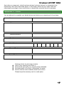
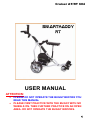
Cruiser AT/RT 604 USER MANUAL ATTENTION: • • PLEASE DO NOT OPERATE THE BUGGY BEFORE YOU READ THIS MANUAL PLEASE FIRST PRACTICE WITH THE BUGGY WITH NO WHEELS ON. THEN FURTHER PRACTICE ON AN OPEN AREA. DO NOT OPERATE THE BUGGY INDOORS. 1 Cruiser AT/RT 604 Contents Welcome to the world of low stress golf ……………………………………………… 3 Safety Notices …………………………………………………………………………… 3 Using your Cruiser - USE BY CARE …………………………………………… 4 Key Components ……………………………………………………………………….. 5 Features …………………………………………………………………………………. 6 Assembly ………………………………………………………………………………… 7 User Controls ……………………………………………………………………………. 11 Caring Batteries ……………….………………………………………………………… 12 Charging batteries ………………………………………………………………………. 12 Technical Specifications ……………………………………………………………… 14 Trouble shooting ………………………………………………………………………. 16 Warranty ………………………………………………………………………………… 16 Warranty card ………………………………………………………………………….. 17 2 Cruiser AT/RT 604 Welcome to the world of low stress golf Welcome and thank you for purchasing the Cruiser Electric golf trolley. The lightweight, powerful Cruiser RT has controllability and ease of use that is second to none. Please take some time to read this manual carefully so that you will get the maximum enjoyment from your Cruiser RT. If you have any questions or queries after reading the manual, please do not hesitate to contact the retailer or supplier. Please be sure to fill in the warranty card and send it to your retailer or supplier as soon as possible. This will register your product to ensure continued support and also qualify you for special promotions which we may run from time to time. If your warranty card is missing please call your retailer or supplier. Safety Notices Do not drop or damage the fully sealed batteries as they contain acid, which may burn skin and could cause blindness. Never attempt to open the battery case or incinerate the battery. Always charge the batteries in a well-ventilated area. During normal use the battery is effectively sealed and practically no acid or gases escape from the case, ensuring a very safe operation of the trolley. However in the event of charging or battery malfunction explosive gas may be released. Keep the battery away from sparks, flames and dangerous chemicals. Always switch off the power at the mains before connecting or disconnecting the charger. Do not put anything metallic near the battery terminals as this may risk short-circuiting the battery with the risk of fire or explosion. Do not place the charging unit on surfaces such as rugs, blankets etc, or near material such as curtains, drapes etc, which may block the ventilation slots. During operation, ensure that the trolley is under control at all times. In the event of a collision, damage to people or property may occur. Cruiser is designed to carry a golf bag of max 20Kg – overloading the trolley may cause damage and will invalidate the warranty. The best result can be achieved with a bag less than 15Kg. (Buggy will be overstressed if the bag weight is more than 15Kg. ) 3 Cruiser AT/RT 604 Using your Cruiser - USE BY CARE We recommend you to have some practise on control of the buggy before you start to use the buggy on golf course. The best practise can be made by removing the rear wheels. 1) The buggy should be operated gently. If you use the buggy roughly, it will break down. It should not be forced over its limits. 2) The buggy should be used responsibly. It has very powerful twin 200W motors. Excessive speed, overloading and misusage may cause problems (which won’t be covered by warranty) 3) The electronic controller of buggy has an overload protection. It will cut off the power if the wheel rotation is blocked or buggy stalls. (Otherwise the electrical system; fuse, controller, etc. would be damaged) When the wheels can’t turn and the energy cannot be transformed into the rotation of the wheels, the electrical current (ampere) will overload and create high temperatures. The controller will sense this and will cut off the power. The Buggy can start again easily right after this situation. However the controller will need to be cooled down by waiting for a few minutes if another attempt is to be made against the obstacle. If a second wheel rotation blockage happens right after the first one, the controller may burn out. The controller may cut the power if the buggy is overloaded and if it is pushed over its climbing capability (Solution: Pushing the buggy by helping it manually over the very steep hills) 4) Do not test the buggy by increasing the speed and torque while holding the buggy while the motor is engaged. The controller will cut off the power; however the electrical system or the motor- gear mechanism may be damaged if this is done repeatedly. 5) Avoid pushing the buggy motor when met with large obstacles. The best way is to go around the obstacle or to help the buggy by pushing it manually. 6) Recommended bag weight is 15Kg. Max. bag weight is given as 20Kg. but buggy will struggle in some terrain conditions if you have a heavy bag. 7) 8) Buggy seats are not stable and should be used carefully. Don’t push down the handlebar to lift up the front wheel for tuning with the rear wheels like a conventional trolley. That may damage the upper plastic locking catch part. It is better to steer the buggy with swivel front wheel. 9) Avoid using the buggy in very heavy rain conditions. 10) Before first use, it is vital that the battery is fully charged. See the later section “Charging the batteries” for more details. 4 Cruiser AT/RT 604 Key Components 1 Handlebar 15 Bottom Locking Catch. Lower Part 2 Speed Control Knob 16 Upper bag Rest Strap 3 Handle Lock bar 17 Seat 4 Umbrella Holder 18 Seat Post 5 Umbrella Holder Bracket 19 Lower Frame Tube 6 Upper Frame Tube 20 Motors 7 Top Locking Catch. Upper Part 21 Lower Bag Rest 8 Top Locking Catch. Lower Part 22 Lower Bag Rest Latches 9 Back Frame Tubes (Left & Right) 23 Lower bag Rest Strap 10 Battery Bag Strap 24 Front Wheel Spring-Lock Assembly 11 Battery Bag (And Battery) 25 Front Wheel 12 Mid. Frame Tube 26 Bottom Frame Side Tubes 13 Upper Bag Rest 27 Rear Wheel 14 Bottom Locking Catch. Upper Part 28 Anti-Tip Wheel 5 Cruiser AT/RT 604 Features Full Remote Control with intelligent controller It can be all controlled with the touch of a button. It can go forward, backward, turn left and right, accelerate, decelerate & brake. The compact hand remote gives you complete freedom. Auto-Lock-Swivel Front Wheel. It makes it one of the easiest handling electric golf buggies on the market today. Turning is very easy now, on manual or remote modes. Easy maneuverability allows the buggy to be controlled with the very lightest of touches. Waterproof Electronics Membrane switches and sealed electronics for waterproofing. Safe Start The motor is prevented from driving the buggy until turn on the speed roller, if the Cruiser is stationary when the power is switched on nothing will happen until the user turn back the roller and on. Electronic Distance Control -TIMER Press the timer button (1,2 or 3 times), your buggy will proceed at the selected speed for the distance (15/30/45M) you have selected. Free Wheeling; If you run out of battery power, want to conserve the power or have a break down, buggy wheels can turn EASILY and COMPLETELY FREE. Overload (Over-current) Protection; If the wheel rotation is blocked or buggy stalls, the electrical current (ampere) will overload and create high temperatures. The controller will sense this and will cut off the power. Otherwise the electrical system; fuse, controller, etc. would be damaged. Overload protection current is set to 30A. Low Battery Protection; The battery is protected from damage as a result of being excessively discharged while the buggy is in use. The effect of this is that when the battery capacity drops 15% of the capacity left, the LED beside the “start” button will flash red and warn you to recharge the battery soon. (The Low Battery Protection Voltage is 9.5V) Electronic Bias Control Motor speeds never can be the same. Different motor speeds will cause a bias. The motor speeds can be electronically aligned by a button on the controller unit. Remote Transmitter Programming A new remote device can be programmed easily by pressing the "Code Learning" button on the controller. No Rust Design The Axle and all fittings made of stainless steel or chrome plated. Because the buggy is nearly waterproof, you can even play under the rain with no hesitation. 6 Cruiser AT/RT 604 Assembly Step 1: Install the rear wheels Before you unfold the buggy frame, it is better to install the rear wheels. Fit the rear wheels by pressing the locking latch on the outside of the wheel while engaging the wheel onto the axle. (Fig.3) Push the wheel until the locking latch catches the axle free wheeling grove or the motor engaged mode grove on the axle. Pull the wheel back to make sure it has been locked on the desired grove. (Please see the axle hub assembly on Fig.4) Install rear wheels Axle hub assembly Step 2: Understand the freewheeling feature: The Cruiser has two stage wheel hub operation (Free Wheeling Mode or Motor Engaged Mode)If you run out of battery power, want to conserve the power or have a break down, buggy wheels can turn completely free like a push trolley by the free wheeling system. Hub Open – Freewheeling mode Hub Closed – Motor engaged 7 Cruiser AT/RT 604 Step 3: Unlock the handlebar locking bar Now your buggy should look like the picture below and ready to be unfolded. Before you unfold the handlebar, unlock the handlebar locking bar from the lower frame. (Unfold the buggy by releasing the top locking catch beneath the handle by sliding it forward) Fig.7 Folded buggy Unlock handle locking bar Step 4: Unfold the frame and the handlebar There are two main locking catches on the main body frame; top and bottom catches. The upper parts of the catches work with spring loaded mechanism. Sliding the upper part backwards will lock or unlock the catches. You should practise this now. Bottom locking catch Top locking catch 8 Cruiser AT/RT 604 Step 5: Install The Battery Cable if it is not connected If you receive the battery with no battery cable attached, please assembly the battery cable with care. Remove the fuse (25 or 30Ah) from the fuse holder first preventing a short during installation. The red cable is Active (+) The black cable is Neutral (-) Please see the battery “Charging the Battery” section. For more details. Step 6: Install The Battery Before connecting battery to the buggy please ensure the buggy is off by turning the power switch to off position and turning the speed control switch fully anticlockwise. Lift up the battery by holding the carry strap. Place the battery in the battery tray. Place the rear side of the battery on the rear side of the tray first. Then push the front side of the battery down on to the tray. (This will help for not touching to the mid. frame tube) Secure the battery using the strap provided. Attention: Always plug and unplug the battery cable by holding the metal plugs and not the cables. Battery-Buggy power plug connection SLA Battery 12V/33Ah Dimensions: 196(L) x 132(W) x 155(H) SLA Battery 12V/24Ah Dimensions: 175(L) x 1126(W) x 166(H) 9 Cruiser AT/RT 604 Step 7: Position The Golf Bag Undo the upper and lower bag rest straps. Rest the golf bag on the mounts and tighten the straps around the top and bottom of the bag. It is important to ensure that the bag is securely attached, as the bag braces the Cruiser handle and integral to the rigidity of the Cruiser. Position the bag centrally so that the weight is proportionate. Lower bag rest Upper bag rest Step 8: Install The Anti-Tip Wheel Anti-tip wheel is assembled with two screws (provided) in to the bar at the rear of the buggy. Anti-Tip wheel assembly Anti-Tip wheel assembled Step 9: Install The Seat Insert the seat bracket in the seat holder on the buggy. Buggy seats are not stable and should be used carefully Seat Bracket Seat Storage 10 Cruiser AT/RT 604 User controls Manual Controls Manual controls are positioned on the T-shape handlebar. The speed is set by a speed control knob at the side of the operation board. This can be set to adjust the speed of the trolley from about 0kph to p to 10kph (depends on the model). The actual speed of the trolley will depend on the speed setting and the terrain. Handlebar Controls On/Off Switch Stand-by Mode Start/Stop (LED1) Timer / Electronic Distance Function The buggy will power on at standby mode when the speed roller is switched on. LED-2 will be GREEN indicating that the unit is ON but the buggy will not start at this time. This is the stand-by mode. START: When the Start/Stop button is pressed buggy will start at the set speed of the speed control knob. LED-1 will be GREEN. And the LED-2 will be on again but will change its colour depending on the battery power status. STOP: When the Start/Stop button is pressed again the buggy will stop. LED-1 will turn to RED and Led-2 will remain the same. Battery Level LED (LED-2) LED-2. When the battery capacity falls lower than 90% the LED will turn ORANGE. The LED will turn RED when the battery is at 10%, warning you to charge the battery soon. Timer / Electronic Distance Function (LED-3) Press the Electronic Distance Function button; Timer LED will blink for 5 seconds and your buggy will proceed at the selected speed for the distance (15/30/45M). Pressing the button once will turn the LED-3 GREEN – indicating that the unit will travel for 15m at the set speed. Pressing the button again will turn the LED-3 RED – indicating that the unit will travel 30m. A third press of the button will turn the LED-3 ORANGE – indicating that the unit will travel 45m. 11 Cruiser AT/RT 604 Remote Control Remote transmitter operates with a battery (provided). The remote range is about 50 meters. This range may vary depending on the terrain conditions, interferences by other sources and the power level of the battery in the remote. Remote control provides 14 speed levels. Speed can be increased or decreased by pressing the (+) or (-) buttons continuously. Attention: Avoid braking on high speed as this may cause damage on buggy. Try slowing down first by pressing the (-) button and then brake. Remote Transmitter Controls Control buttons & LEDs on Controller Remote Operation The remote operation is very straight forward. You just need to switch on the buggy to STAND-BY MODE by turning the speed control knob. Then just press the remote buttons. The buggy can easily be controlled to all directions by this remote device. (Only reverse operation needs more care and practise because of the swivel front wheel) Electronic Bias Alignment Motor speeds never can be the same. There may be a difference of between 5% more or less between the motors. Different motor speeds will cause a bias and the buggy will not go straight. The motor speeds can be electronically aligned by a button on the controller. The power to the right hand side motor can be adjusted and made the same with the left hand side motor. This should be done while the golf bag is loaded on the buggy. Remote Signal LED There is a LED light both on remote transmitter and controller. They blinks simultaneously each time you send a signal by the remote transmitter. Remote Code Learning If you need to use a new remote transmitter for your buggy (lost or damaged), you need to program the new remote transmitter. 1) Start the buggy by turning the speed control knob. 2) Press the Remote Control Learning Button on the controller. 3) Press any of the buttons on the remote transmitter. The Remote Signal LED will be on for 5 seconds then will be off. 4) Now the remote transmitter has learned the code. 12 Cruiser AT/RT 604 CARING BATTERIES The SLA AGM batteries typically achieve a working lifetime about 250-300 cycles, depending on the depth of cycling and the operating temprature. However their life will be shorter after each time they are charged. So, they should be considered as consumable products. A good battery using and charging technique will also make a big difference on the battery life. They must be looked after correctly. • Never forget that your battery has a certain amount of power. (e.g. 24Ah, 26Ah, 28Ah, 33Ah) The power in it is not endless. The standard batteries are adequate for 18 holes providing they are played on the same day. • If the battery is used heavily during the golf game, it may run out of power before finishing the 18th hole. (SOLUTION: PUSHING THE BUGGY A LITTLE BIT OVER THE STEEP HILLS WILL CONSERVE A HUGE AMOUNT OF BATTERY POWER ) • Heavy usage, hilly terrain and low temperatures affect battery performance. 18 holes are based on normal conditions. • The batteries should never be run flat by being used with low power. The deeper the discharge, the shorter the life of the battery. However the Cruiser has a Low Battery Protection which will cut off the power when the battery power drops down less than 15%. The low battery protection voltage is 9.5V. • The batteries must be charged as soon as possible after they have been used. Even if they are only used for a few holes, they must be recharged immediately. Deep cycle batteries deteriorate quickly when left for prolonged periods partially charged. Even being left partially discharged over night will reduce its life. • Overcharging a sealed battery by keeping on charge longer than necessary will drive off moisture, which is impossible to replace and will shorten the battery life (The Cruiser comes with an Automatic Charger which will prevent overcharging) • Never leave the battery connected to the trolley when it is not in use even if the trolley is switched off as this can drain the batteries. • If the battery is not used for a long period of time, charge it fully, then disconnect it from the charger and store it in a cool place. When it is stored like this, be sure to recharge them fully, at least once every two months. CHARGING BATTERIES PLEASE CHARGE THE BATTERY FULLY BEFORE YOUR FIRST USAGE Cruiser Buggies come with an Automatic Charger (3Ah, 3-Stage, 600mAh Trickle charging). • Only use the approved charger that is supplied with the buggy. The use of any other charger may damage the batteries and charger, and will void the warranty. • Never connect the charger to power point first. Always connect the charger to the battery first, and then plug it to the power point. • If the charger is switched off, be sure to also disconnect the batteries. • Always switch off the power at the mains before you disconnect the charger from the battery. • The charger should be taken away from the power supply right away when it overheats 13 Cruiser AT/RT 604 • Don’t use the charger in overly wet and high temperature environments. • Don’t open the charger to repair it. The charger has two lights which monitor the charging process. RED- the mains power is on and the batteries are charging rapidly. (Rapid Charge) GREEN – the batteries are in the last charging phase. This final stage of the process is very important to battery life and must be allowed to complete. Within 1-2 hours of this charging stage (i.e. after the battery charger light has changed from red to green) the batteries are fully charged and are being maintained at peak charge by the charger (Trickle Charge) Once fully charged it is desirable to leave the charger connected and switched on until the buggy is to be next used. Charging TimeThe charger supplied with your Cruiser will go from RED (rapid charge) to Green (trickle charge) within a maximum of 12 hours. If the charger remains on red for a longer period them please disconnect the charger as the battery may be damaged .If this problem persists call your supplier. If the charger is switched off, be sure to disconnect the batteries. If the batteries are not used for long periods of time, charge them fully, disconnect them from the charger and store them in a cool, dry place. When stored like this be sure to recharge them for 24 hours at least once every two months. Battery Cable and Fuse The battery is fused (25/30A) to protect from over current .The fuse is located inside the battery bag and should be checked in case of apparent power failure. If you receive the battery with no battery cable attached, please assembly the battery cable with care. Remove the fuse (25 or 30Ah) from the fuse holder first preventing a short during installation. The red cable is Active (+) The black cable is Neutral (-) The 3 pin round plug has a guide pin (no.3) to prevent incorrect connection and avoids reverse polarity. Fuse holder Battery cable plug configuration 14 Cruiser AT/RT 604 TECHNICAL SPECIFICATIONS Frame High strength aluminium Motor Dual 200W / 12 Volt (RT Model) Speed Adjustable from 1-10km/hr (depends on the terrain) Climbing 15-20 degree (depends on the terrain and battery state) Remote range (RT Model) 40-60 metre; depends on the terrain and interference conditions. Weight 22.50 Kg. Buggy with battery 12.50 kg Buggy + 11 Kg Battery - RT Model 19.50 Kg. Buggy with battery 11.50 kg Buggy + 8 Kg Battery - AT Model Dimensions Unfolded: 119 (L) x 64 (W) X 90(H) mm Folded: 83 (L) x 64 (W) X 37 (H) mm Golf Bar Rating Optimum: 14 Kg, Max. 20 Kg. Range 18 holes with 36 Ah battery – RT Model 18 holes with 24 Ah battery – AT Model Battery 12V/33Ah SLA AGM –RT Model 12V/24Ah SLA AGM –AT Model Fuse Rating 25A Recommended, Max. 30A Battery Charger Three stage automatic 12VDC / 3.0A output 15 Cruiser AT/RT 604 TROUBLESHOOTING We believe that your Cruiser is the most reliable golf trolley available. It has no gears to wear, No brushes to wear, and a very reliable battery. All pivots have been designed to eliminate wear. The following will guide you if you have any problem : Symptom Cause Remedy The cruiser works for a while, but slows and then stops before you complete your round. Battery not holding the full charge. Cruiser won’t go. Check that the battery is connected. The battery may be old or the charger may be faulty. DO NOT TRY ANOTHER CHARGER. unless it is a Cruiser charger. Return the battery and charger to the retailer for testing. Check the battery connector, switch and speed control setting. Cruiser won’t go. Battery is completely flat or there is a wiring or component problem. The battery inside the transmitter is flat or there is a wiring or component problem. Cruiser can’t be controlled by the transmitter ,or the remote distance is less. Don’t connect it to your charger. Return it to your retailer. Change the battery, if still not ok, return it to your retailer. WARRANTY Each Cruiser has been carefully inspected and tested prior to dispatch. Accordingly, the trolley and charger are guaranteed against failure due to defective materials & workmanship, under normal usage ,for one(1) year from date of purchase. The obligation under this warranty shall be limited to the repair or replacement of any trolley or component returned within the warranty period , which ,upon examination, proves to have been defective. This warranty excludes any claim for consequential damages or loss, however caused. Replacement may be with new or reconditioned components at the discretion of the repair This guarantee is made on a Return – to – Supplier basis. Freight , postage , or transport costs are not included. This warranty is applicable only to the initial purchaser ,and is not transferable. Original proof of purchase is required . The battery is warranted for one(1) year, from the date of purchase ,against faulty workmanship or material. If the battery is damaged due to excessive discharging or due to leaving it in a discharged state this warranty is void. If the warranty claim on a battery is not allowed , then the customer will be charged for testing and return freight . 16 Cruiser AT/RT 604 Any trolley or component which has been abused ,misused ,altered ,or attempted to be repaired by other than authorised agent, or any battery which has not been used and maintained according to these instructions ,is specifically excluded from this warranty. WARRANTY CARD You are advised to complete your details below and attach your original proof of purchase. Name Address Telephone/Mobile Email Serial Number Place of Purchase Date of Purchase ◆ ◆ ◆ ◆ Packing advice for returning products: Pack it very carefully and insure it. Enclose this card with your original receipt attached. Enclose details of the fault / instructions for repair. Ensure that the return address details are correct . Please keep this warranty card in a safe place. 17