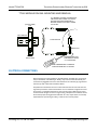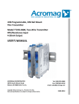
1
USB Programmable, DIN Rail Mount Thin Transmitter Model TT334-0700 NTC Thermistor/Potentiometer/Rheostat Input Universal Current & Voltage Output USER’S MANUAL ACROMAG INCORPORATED 30765 South Wixom Road Wixom, MI 48393-7037 U.S.A. Copyright 2014, Acromag, Inc., Printed in the USA. Data and specifications are subject to change without notice. Tel: (248) 295-0880 Fax: (248) 624-9234 email: [email protected] 8500-996E Model TT334-0700 Thermistor/Potentiometer/Rheostat Transmitter w/USB Table of Contents GETTING STARTED DESCRIPTION............................................................................................ 4 Key Features ........................................................................................................................4 Application ..........................................................................................................................4 Mechanical Dimensions .......................................................................................................5 DIN Rail Mounting & Removal ..............................................................................................5 ELECTRICAL CONNECTIONS ....................................................................... 6 Sensor Input Connections ....................................................................................................7 Output Connections .............................................................................................................8 Power Connections ..............................................................................................................9 Optional Bus & Redundant Power Connections .................................................................. 10 Earth Ground Connections ................................................................................................. 11 USB Connections................................................................................................................ 12 CONFIGURATION SOFTWARE.................................................................. 13 Quick Overview ................................................................................................................. 13 OPERATION STEP-BY-STEP ...................................................................... 15 Connections....................................................................................................................... 15 Configuration..................................................................................................................... 17 Calibration (Optional) ........................................................................................................ 21 Thermistor Resistance versus Temperature ........................................................................ 23 BLOCK DIAGRAM .................................................................................... 24 How It Works ..................................................................................................................... 24 TROUBLESHOOTING ............................................................................... 25 Diagnostics Table ............................................................................................................... 25 Service & Repair Assistance ............................................................................................... 26 Acromag, Inc. Tel: 248-295-0880 [2] -2- http://www.acromag.com http://www.acromag.com Model TT334-0700 Thermistor/Potentiometer/Rheostat Transmitter w/USB ACCESSORIES.......................................................................................... 27 Software Interface Package................................................................................................ 27 USB Isolator ....................................................................................................................... 27 USB A-B Cable .................................................................................................................... 27 USB A-mini B Cable ............................................................................................................ 27 SPECIFICATIONS ..................................................................................... 28 Model Number .................................................................................................................. 28 Input ................................................................................................................................. 28 Output............................................................................................................................... 30 USB Interface ..................................................................................................................... 32 Power ................................................................................................................................ 32 Enclosure & Physical .......................................................................................................... 33 Environmental ................................................................................................................... 33 Agency Approvals .............................................................................................................. 34 Reliability Prediction .......................................................................................................... 34 Configuration Controls ....................................................................................................... 34 REVISION HISTORY ................................................................................. 35 All trademarks are the property of their respective owners. IMPORTANT SAFETY CONSIDERATIONS It is very important for the user to consider the possible adverse effects of power, wiring, component, sensor, or software failures in designing any type of control or monitoring system. This is especially important where economic property loss or human life is involved. It is important that the user employ satisfactory overall system design. It is agreed between the Buyer and Acromag, that this is the Buyer's responsibility. The information of this manual may change without notice. Acromag, Inc. makes no warranty of any kind with regard to this material, including, but not limited to, the implied warranties of merchantability and fitness for a particular purpose. Further, Acromag, Inc. assumes no responsibility for any errors that may appear in this manual and makes no commitment to update, or keep current, the information contained in this manual. No part of this manual may be copied or reproduced in any form without the prior written consent of Acromag, Inc. Acromag, Inc. Tel: 248-295-0880 [3] -3- http://www.acromag.com http://www.acromag.com Model TT334-0700 Thermistor/Potentiometer/Rheostat Transmitter w/USB GETTING STARTED DESCRIPTION The TT334-0700 is an ANSI/ISA Type 4 transmitter designed to interface with thermistors and potentiometers/rheostats, isolate the input signal, and modulate a DC current or DC voltage signal at its output. Thermistor sensor excitation, linearization, and lead break or sensor burnout detection are supported. Configuration is performed using Windows software and a USB connection to Windows-based PC’s (Windows XP and later versions only). Key Features Fully configurable via USB using Windows software. Thin 17.5mm wide enclosure for high-density DIN-rail mounting. High measurement accuracy and linearity. NTC Thermistors, Potentiometers, and Rheostats supported. User customizable Thermistor Linearization Table. Thermistor inputs are linearized with respect to temperature. Supports Celsius, Fahrenheit, and Kelvin temperature units. Up or down-scale lead-break/burnout detection. Adjustable input range and selectable output ranges. Input, output, and power circuits are fully isolated from each other. Universal output for ±10V, 0-10V, ±5V , 0-5V, ±20mA, 0-20mA, and 4-20mA. Output drives DC current or DC voltage without rewiring. Normal or reverse acting output. Variable input filter adjustment. Wide-range DC power input from 12–32VDC. Wide ambient temperature operation. Thoroughly tested and hardened for harsh environments. CE Approved. UL/cUL Class1, Division 2 Approved. Application For additional information on these devices and related topics, please visit our web site at www.acromag.com. The TT334 transmitter is designed for high-density mounting on 35mm T-type DIN rails. Modules may be mounted side-by-side on 0.7 inch (17.5mm) centers. 12–32V DC power is supported via terminals on the module, or optionally via power wired to its DIN-rail bus connector. This model accepts thermistor and potentiometer/rheostat inputs and isolates the input signal allowing it to mate with grounded or non-grounded input signals. The universal output signal is isolated from the input and power and will drive current or voltage signals for the ranges ±20mA, 0–20mA, 4–20mA, ±10V, 0–10V, ±5V, and 0–5V. The output of this transmitter is unique in that it can drive either current or voltage under digital control using the same terminals. Acromag, Inc. Tel: 248-295-0880 [4] -4- http://www.acromag.com http://www.acromag.com Model TT334-0700 Thermistor/Potentiometer/Rheostat Transmitter w/USB Mechanical Dimensions 17.5 (0.69) 99.0 (3.90) Modules may be mounted to 35mm “T” type DIN rail (35mm, type EN50022), and side-by-side on 17.5mm (0.7-inch) centers. CAUTION: IEC Safety Standards may require that this module be mounted within an approved metal enclosure or subsystem, particularly for applications with exposure to voltages greater than or equal to 75VDC or 50VAC. 114.5 (4.51) DIMENSIONS ARE IN MILLIMETERS (INCHES) DIN Rail Mounting & Removal Refer to the following figure for mounting and removing a module from the DIN rail. Mounting A spring loaded DIN clip is located on the input side bottom. The rounded edge of the output side bottom allows the module to tilt upward so that it may be lifted from the rail when prying the spring clip back with a screwdriver. To attach a module to T-type DIN rail, angle the top of the module towards the rail and place the top groove of the module over the upper lip of the DIN rail. Firmly push the module downward towards the rail until it snaps into place. Removal To remove a module from the DIN rail, first separate the input terminal blocks from the bottom side of the module to create a clearance to the DIN mounting area. A screwdriver can be used to pry the pluggable terminals out of their sockets. While holding the module in place from above, insert a screwdriver into the lower path of the bottom of the module to the DIN rail clip and use it as a lever to force the DIN rail spring clip down while pulling the bottom of the module outward until it disengages from the rail. Tilt the module upward to lift it from the rail. Acromag, Inc. Tel: 248-295-0880 [5] -5- http://www.acromag.com http://www.acromag.com Model TT334-0700 Thermistor/Potentiometer/Rheostat Transmitter w/USB TT3XX MODULE DIN RAIL MOUNTING AND REMOVAL TILT MODULE UPWARD TOWARDS RAIL AND HOOK ONTO UPPER LIP OF RAIL. ROTATE MODULE DOWNWARD TO ENGAGE SPRING CLIP ONTO LOWER LIP OF RAIL. (OUTPUT SIDE) TOP TT300 Series 35mm DIN Rail TT3XX MODULE USB T-Rail SPRING CLIP BOTTOM (INPUT SIDE) SCREWDRIVER SLOT FOR REMOVAL FROM "T" TYPE DIN RAIL USE SCREWDRIVER TO REMOVE MODULE FROM RAIL AS SHOWN ELECTRICAL CONNECTIONS Wire terminals can accommodate 12–26 AWG solid or stranded wire. Input wiring may be shielded or unshielded type. Ideally, output wires should be twisted pair. Terminals are pluggable and can be removed from their sockets by prying outward from the top with a flat-head screwdriver blade. Strip back wire insulation 0.25-inch on each lead and insert the wire ends into the cage clamp connector of the terminal block. Use a screwdriver to tighten the screw by turning it in a clockwise direction to secure the wire (0.5-0.6Nm torque). Since common mode voltages can exist on signal wiring, adequate wire insulation should be used and proper wiring practices followed. As a rule, output wires are normally separated from input wiring for safety, as well as for low noise pickup. Acromag, Inc. Tel: 248-295-0880 [6] -6- http://www.acromag.com http://www.acromag.com Model TT334-0700 Thermistor/Potentiometer/Rheostat Transmitter w/USB Sensor Input Connections Sensor wires are connected directly to the transmitter input terminals at the bottom of the transmitter (the spring-loaded DIN clip side), as shown in the connection drawing below. Transmitter Input Signal is Isolated from Output. Inputs are polarized. “+” and “–“ connections for Thermistors and Rheostats can be swapped. “H” and “–” connections for Potentiometers can be swapped to reverse the direction of the input signal with respect to the direction of the Potentiometer. Observe the wiper input “W” when connecting a Potentiometer. Only one input sensor may drive the output at one time. NOTE: Sensor lead-wire resistance will contribute an input shift for Thermistor and Rheostat input types. See Input Sensor Information below. BOTTOM VIEW (INPUT SIDE) MODEL TT334-0700 INPUT SENSOR WIRING OPTIONAL EARTH GROUND. (SEE NOTE 1) SHIELDED CABLE MIN 2 POTENTIOMETER 4 5 OPTIONAL SHIELD GROUND. (SEE NOTE 2) 2 3 4 W 5 H 6 – OUTPUT & POWER SIDE TB1 (INPUT) TB3 (OUTPUT) – 3 NC MAX 1 1 NC INPUT SIDE W TB2 (INPUT) MODEL TT334-0700 TB4 (POWER) H 6 NC NOTE 1: DO NOT GROUND THE INPUT SENSOR IF UNIT IS CONNECTED TO A GROUNDED PC WITHOUT A USB ISOLATOR. BUS CONNECTOR (OPTIONAL POWER) NOTE 2: SHIELDED CABLE IS RECOMMENDED. FOR BEST RESULTS, GROUND THE CABLE SHIELD AT THE END OF THE CABLE CLOSEST TO THE GREATEST POTENTIAL SOURCE OF DISTURBANCE, USUALLY THE SENSOR END. SHIELDED CABLE + 1 OR THERMISTOR RHEOSTAT – DIN RAIL SPRING CLIP BOTTOM VIEW (INPUT SIDE) 2 OPTIONAL SHIELD GROUND. (SEE NOTE 2) OPTIONAL EARTH GROUND. (SEE NOTE 1) + 2 – 3 TB1 (INPUT) – 3 NC 4 NC 5 NC 6 NC Acromag, Inc. Tel: 248-295-0880 1 + INPUT SENSOR INFORMATION 4 5 6 TB2 (INPUT) POTENTIOMETER : A 3-WIRE VARIABLE RESISTOR USED TO FORM A VOLTAGE DIVIDER. VOLTAGE IS MEASURED RATIOMETRICALLY (AT WIPER LEAD) WITH RESPECT TO INPUT EXCITATION AND GROUND. VARIATIONS DUE TO SENSOR LEAD-WIRE RESISTANCE AND CHANGE IN RESISTANCE OVER TEMPERATURE ARE NULLIFIED BY USING A RATIOMETRIC MEASUREMENT TECHNIQUE. THERMISTOR : A 2-WIRE SENSOR THAT VARIES RESISTANCE WITH SENSED TEMPERATURE. INPUT RESISTANCE FORMS A VOLTAGE DIVIDER WHICH IS USED TO CALCULATE THE SENSED TEMPERATURE BY COMPARING THE MEASURED RESISTANCE WITH KNOWN THERMISTOR CHARACTERISTICS. SENSOR LEAD-WIRE RESISTANCE WILL CONTRIBUTE A NEGATIVE SHIFT TO THE SENSOR MEASUREMENT. RHEOSTAT : A 2-WIRE VARIABLE RESISTOR USED TO FORM A VOLTAGE DIVIDER. VOLTAGE IS MEASURED WITH RESPECT TO KNOWN INPUT IMPEDANCE (TOTAL RESISTANCE OF RHEOSTAT) IN ORDER TO CALCULATE THE SENSOR RESISTANCE. SENSOR LEAD-WIRE RESISTANCE WILL CONTRIBUTE A POSITIVE SHIFT TO THE SENSOR MEASUREMENT. [7] -7- http://www.acromag.com http://www.acromag.com Model TT334-0700 Thermistor/Potentiometer/Rheostat Transmitter w/USB Output Connections (DC Current or Voltage) Output connections are polarized. Current is output from Output+ and returns to Output–. Voltage output is positive at Output+. NOTE: This transmitter is an ANSI/ISA Type 4 in which the transmitter’s power is isolated from the input and output circuits. Variations in load resistance have negligible effect on output accuracy, as long as load limits are respected with respect to output type. Note the placement of earth ground. The output cable shield and return should ideally be grounded closest to the transmitter. Only one end of the connection should be grounded, never both. MODEL TT33X-0700 OUTPUT WIRING OUTPUT WIRED FOR DC CURRENT OR VOLTAGE INPUT SIDE OUTPUT & POWER SIDE TOP VIEW (OUTPUT & POWER SIDE) CURRENT OUTPUT TB1 (INPUT) TB3 (OUTPUT) 7 – 8 – I 9 + 9 + – 8 SHIELDED CABLE IOUT + + – – R TB2 (INPUT) ANY MODEL TT33X-0700 TB4 (POWER) 10 11 12 – – 1 + LOAD = 525? MAX RESISITANCE: 525? MAX CAPACITANCE: 100µF MAX INDUCTANCE: 15mH 7 – 2 CURRENT OUTPUT LOAD DRIVES 20mA INTO 525? MAX (0–20mA, 4–20mA, ±20mA) EARTH GROUND AT 1 OR 2 , BUT NOT BOTH OR VOLTAGE OUTPUT 9 + – 8 VOUT SHIELDED CABLE + + – – 7 – RLOAD = 1K? MIN RESISITANCE: 1000? MAX CAPACITANCE: 100µF 1 2 EARTH GROUND AT 1 OR 2 , BUT NOT BOTH DIN RAIL SPRING CLIP VOLTAGE OUTPUT LOAD DRIVES 10V INTO 1K? MIN (0–10V, 0–5V, ±5V, ±10V) Observe proper polarity. Note that twisted-pair wiring is often used to connect the longest distance between the field transmitter output and the remote load as shown above. Additionally, shielded twisted pair wiring is recommended for best results. An output connection to earth ground will help protect the circuit from damage in noisy environments. WARNING: For compliance to applicable safety and performance standards, the use of twisted pair output wiring is recommended. Failure to adhere to proper wiring and grounding practices as instructed may compromise safety, performance, and possibly damage the transmitter. TIP – Ripple & Noise: Additional filtering placed at the load can help reduce 60Hz/120Hz ripple often present in industrial applications. For large 60Hz supply ripple, connect an external 1uF or larger capacitor directly across the load to reduce excessive ripple. For sensitive applications with high-speed acquisition at the load, high frequency noise may be reduced significantly by placing a 0.1uF capacitor directly across the load, as close to the load as possible. Acromag, Inc. Tel: 248-295-0880 [8] -8- http://www.acromag.com http://www.acromag.com Model TT334-0700 Thermistor/Potentiometer/Rheostat Transmitter w/USB Power Connections This transmitter is powered from 12–32VDC (36VDC peak) by connecting power as shown below. This transmitter can be optionally powered (or redundantly powered) via the DIN rail bus when coupled to the DIN rail bus connector (Acromag Model 1005-063) and a bus terminal block (Acromag 1005-220 or 1005-221). This optional method can allow several modules to share a single power supply without wiring to each individually. Power connections are isolated from input and output. The supply voltage should be from 12–32VDC. This voltage must never exceed 36VDC peak, or damage to the transmitter may result. Variations in power supply voltage between the minimum required and 32VDC maximum, has negligible effect on transmitter accuracy. Note the placement of earth ground at input power. The power cable shield and DC– should ideally be grounded closest to the transmitter. Only one end of the connection should be grounded, never both. CAUTION – Risk of Electric Shock: More than one disconnect switch may be required to de-energize this equipment before servicing. IMPORTANT – External Fuse: If the transmitter is powered from a supply capable of delivering more than 2.5A to the transmitter, it is recommended that this current be limited via a high surge tolerant fuse rated for a maximum current of 2.5A or less (for example, see Bel Fuse MJS or RJS fuse types). MODEL TT33X-0700 POWER WIRING UNIT IS DC-POWERED ONLY AT 12 TO 32VDC. INPUT SIDE OUTPUT & POWER SIDE TB1 (INPUT) TOP VIEW (OUTPUT & POWER SIDE) TB3 (OUTPUT) 7 – 8 – 9 + POWER IS ISOLATED FROM SIGNAL INPUT AND OUTPUT CIRCUITS. TB2 (INPUT) TB4 (POWER) ANY MODEL TT33X-0700 10 11 12 – – + * FUSE 12 + 11 – + – 10 – DC SUPPLY (12–32V) 1 EARTH GROUND AT 1 OR 2 , BUT NOT BOTH 2 CAUTION: DO NOT EXCEED 36VDC, OR DAMAGE TO THE UNIT MAY RESULT. BUS CONNECTOR (OPTIONAL POWER) * NOTE: IT IS RECOMMENDED THAT SUPPLIES CAPABLE OF SOURCING MORE THAN 2.5A TO THE UNIT BE FUSED WITH A HIGH SURGE TOLERANT FUSE. DIN RAIL SPRING CLIP Acromag, Inc. Tel: 248-295-0880 [9] -9- http://www.acromag.com http://www.acromag.com Model TT334-0700 Thermistor/Potentiometer/Rheostat Transmitter w/USB Optional Bus & Redundant Power Connections Power is normally connected to the TB4 power terminals of the transmitter as shown on the previous page. However, this transmitter is equipped to be optionally powered via its DIN rail bus connector provided (Acromag 1005-063), when mated to an optional plug-in terminal block (Acromag 1005-220 or 1005-221). Power input via the bus connector terminal is diode-coupled to the same point as transmitter power connected at TB4 power. Multiple modules may be powered by snapping them together along the DIN rail bus, then using the mating terminal block shown at left (select a Left or Right side connector). While the intent of the bus power connector is to allow several modules to conveniently share a single supply, the bus power connector may also be used to redundantly power modules, allowing a backup supply to maintain power to the module(s) should the main supply at TB4 fail. This transmitter comes equipped with the bus connector 1005-063 shown below. This connector allows modules to snap together, side-by-side, along the DIN rail and share these connections. To complete connection to power, an optional bus terminal block is needed (Acromag 1005-220 for left-side, or 1005-221 for right-side connections). Refer to the figure on the following page which shows how to wire power to the optional bus connector using these connectors. TT300 Series TT300 Series TT300 Series TT300 Series TT300 Series TT300 Series USB USB USB USB USB USB 35mm DIN Rail DIN Rail Bus Connector Acromag 1005-063 (Included with Module) Acromag, Inc. Tel: 248-295-0880 [ 10 ] - 10 - http://www.acromag.com http://www.acromag.com Model TT334-0700 Thermistor/Potentiometer/Rheostat Transmitter w/USB Optional Bus & Redundant Power Connections… The figure below shows how to wire power to the optional bus terminal block when mated to the bus connector. Note that power is wired to the rightmost bus terminals on the right, or the left-most terminals on the left. Observe proper polarity. YOU CAN OPTIONALLY CONNECT POWER TO THE DIN RAIL BUS CONNECTOR ALONG THE DIN RAIL USING THE OPTIONAL TERMINALS AS SHOWN. TT300 Series RIGHT LEFT 35mm DIN RAIL DIN RAIL BUS POWER DC – DC + – + – DC – + DC + USB – + * FUSE DC SUPPLY (12–32V) FEMALE TERMINAL BLOCK ACROMAG 1005-220 (LEFT-SIDE CONNECTION) + – MALE TERMINAL BLOCK ACROMAG 1005-221 (RIGHT-SIDE CONNECTION) EARTH GROUND CAUTION: DO NOT EXCEED 36VDC, OR DAMAGE TO THE UNIT MAY RESULT. * NOTE: IT IS RECOMMENDED THAT SUPPLIES CAPABLE OF SOURCING MORE THAN 2.5A TO THE UNIT BE FUSED WITH A HIGH SURGE TOLERANT FUSE. Earth Ground Connections The module housing is plastic and does not require an earth ground connection. It does include a special connector that makes functional contact with the DIN rail if the DIN rail is grounded, but do not rely on this connection for earth ground. The internal input, output, and power circuits are electrically isolated from each other, allowing these circuits to be individually earth grounded as indicated. If the module is mounted in a metal housing, a ground wire connection is typically required for the enclosure and the metal enclosure’s ground terminal (green screw) should be connected to earth ground using suitable wire per applicable codes. See the Electrical Connections Drawings for Input, Output, and Power, and note the position of earth ground. Earth ground should be applied at the input power minus terminal (DC–). The input and output circuits are shunted to earth ground applied at the power minus terminal via internal isolation capacitors. Avoid inadvertent connections to earth ground at points other than those indicated, as this could drive ground loops and negatively affect operation. A USB isolator is recommended when configuring or calibrating a transmitter to avoid the ground loop that occurs if the input sensor is also earth grounded (PC USB ports are commonly earth grounded and make contact with both the USB signal and shield ground which is held in common to the input circuit ground of the transmitter). Acromag, Inc. Tel: 248-295-0880 [ 11 ] - 11 - http://www.acromag.com http://www.acromag.com Model TT334-0700 Thermistor/Potentiometer/Rheostat Transmitter w/USB USB Connections This transmitter is configured and calibrated via configuration software that runs on Windows-based PCs connected to the transmitter via USB (Windows XP or later version required). Refer to the following drawing to connect a PC to the transmitter for the purpose of configuration TT SERIES USB TRANSMITTER CONNECTIONS USED FOR CONFIGURATION AND CALIBRATION OF THE TRANSMITTER IN A SAFE OR ORDINARY LOCATION – TB4-11 + TB4-12 PERSONAL COMPUTER RUNNING WINDOWS OS – HOST PC RUNNING ACROMAG CONFIGURATION SOFTWARE TB4 TB3 (POWER) (OUTPUT) + DC POWER SUPPLY 12 – 32V USB MiniB MALE USB MiniB Socket (Front-Panel of Module) HOST USB TO HOST USB PORT TB2 (INPUT) TB1 (INPUT) USB-A MALE Refer to Configuration Software Kit, Model TTC-SIP, which includes: 1 ea, Model 4001-113 USB Cable 1 ea, Model 4001-112 USB Cable 1 ea, Model USB-ISOLATOR 1 ea, Configuration Software CDROM 5040-944 WARNING: The intent of mating USB with this transmitter is so that it can be conveniently configured and calibrated in a safe area, then installed in the field which may be in a hazardous area. Do not attempt to connect a PC or laptop to this transmitter while installed in a hazardous area, as USB energy levels could ignite explosive gases or particles in the air. USB-A MALE USB-B MALE DEVICE CONNECT 1 METER USB CABLE Model 4001-112 PC CONNECT HOST USB SERIAL PORT CONNECTOR AT BACK OF PC CABLE Model 4001-113 MODEL TT3XX TRANSMITTER POWER RESET CONNECTION MODEL NO. - USB-ISOLATOR (RECOMMENDED) USB Signal Isolation is recommended and required when connected to a grounded input. Input and USB connections are isolated from the output of this transmitter. USB isolation is recommended for safety and noise suppression reasons, but required when the input signal is grounded (i.e. when non-insulated or grounded sensors are used). Acromag model USB-ISOLATOR may be used to isolate the USB port, or optionally a different USB signal isolator that supports USB Full Speed operation (12Mbps). IMPORTANT: USB logic signals to the transmitter are referenced to the potential of the transmitter’s input ground. This ground is held in common with USB ground and USB cable shield ground. Thus, an isolator is required when the input signal is grounded and the transmitter is connected to the USB port of an earth-grounded PC. The use of an isolator can be avoided if a battery powered laptop PC is used to connect to the transmitter, and the laptop has no other earth ground connection, either directly or via a connected peripheral. Acromag, Inc. Tel: 248-295-0880 [ 12 ] - 12 - http://www.acromag.com http://www.acromag.com Model TT334-0700 Thermistor/Potentiometer/Rheostat Transmitter w/USB CONFIGURATION SOFTWARE Quick Overview Click “Open” to connect to the TT334-0700 and the software will look similar to the following: This transmitter can only be configured and calibrated via its configuration software and a USB connection to a PC or laptop. The configuration software is contained in a zip file that can be downloaded free of charge from our web site at www.acromag.com. If you do not yet have a user account, you will need to create one before the download becomes accessible. The zip file will extract to an executable file which installs software to the “/Program Files/Acromag” directory on your computer. Note: You need administrator privileges on the PC you wish to install this software. Once installed, navigate to the “/Program Files/Acromag” directory and open the correct software for your particular model. This software is also included on a CDROM bundled with the Configuration Kit TTC-SIP (see Accessories). For this transmitter, use the software named “TT334 Config.exe”. Communication Setup (First Connect to Transmitter Here) Select from connected transmitters and Open/Close communication with them. Display the Model, Serial Number, and Manufacturer of the connected transmitter and report the status of communication. I/O Config/Test (Configure and/or Test the Transmitter Here) Optional - Click the [Get I/O Config] button to retrieve the I/O configuration of the currently connected transmitter. Select the Input Type: Potentiometer/Slidewire, Thermistor, or Rheostat. Select the level of digital filtering: High, Medium, Low or None. The corresponding I/O response times are listed in parenthesis next to the filter selection. Select the Break Direction: Under-range or Over-range, if applicable. Select the Output Range: ±5V, ±10V, 0-5V, 0-10V, ±20mA, 0-20mA, or 4-20mA. Select the temperature units to use in the I/O Configuration, if applicable. Enter the I/O Scaling. Specify the input temperatures or percentages to correspond to Zero-Scale and Full-Scale. Submit the configuration settings to the transmitter by clicking the [Send I/O Config] button to write the settings to the non-volatile EEPROM memory. I/O Test (Optional, Verify Transmitter Operation Here) After making I/O configuration changes, you can use the I/O Test controls to start/stop polling the input channel to check your input readings. Click “Start Polling” to periodically read your input channel and validate its operation. Click “Stop Polling” to stop polling the input channel. Note the simulated red lamp next to the button flashes slowly when the software is polling the input channel. For detailed configuration and calibration procedures, see the Operation Step-By-Step section of the Technical Reference of this manual. Acromag, Inc. Tel: 248-295-0880 [ 13 ] - 13 - http://www.acromag.com http://www.acromag.com Model TT334-0700 Thermistor/Potentiometer/Rheostat Transmitter w/USB Quick Overview... Thermistor Config Table – For Thermistor Input Types Only (Define the Thermistor Characteristics Here) Optional - Click the [Read Table from Unit] button to retrieve the Thermistor table stored on the currently connected transmitter. Select the Table Preset. Templates will automatically fill out the temperature column. Set the number of Break-points, i.e. the number of rows in the Thermistor table. Select the temperature units to use in the Thermistor Config Table. Select the resistance multiplier. This determines if the Thermistor Config Table resistance is in Ohms or Kilohms. Click the [Validation Check] button to have the configuration software check the Thermistor table breakpoints for extraneous or erroneous values. Breakpoints that need attention are highlighted. Submit the Thermistor table to the transmitter by clicking the [Send Table to Unit] button to write the table to the non-volatile EEPROM memory. CALIBRATION (Calibrate the Input and/or Output if Needed) This transmitter has already been factory calibrated. If you encounter excessive error, you can click the Calibration tab to display the Calibration control page as shown at left. To calibrate the Input or Output stage of this transmitter, simply click the respective “Cal Instructions” button and follow the prompts. Input… Click the [Input Cal Instructions] button to begin input calibration. When you click [Zero-Scale] or [Full-Scale] of the Input Calibration section, you will be prompted to connect input pins together or apply a specific resistance at the input terminals. Once you have applied this resistance or connected the correct input pins, click the [OK] button of the prompt to calibrate. HELP: You can press [F1] for Help on a selected or highlighted field or control. You can also click the [?] button in the upper-right hand corner of the window and click to point to a field or control to get a Help message pertaining to the item you pointed to. Output… Click the [Output Cal Instructions] button to begin output calibration. When you click [Zero-Scale] or [Full-Scale] of the Output Calibration section, you will be prompted to measure the output signal and enter the measurements in the field provided. Click the [Submit Measurement] button to calibrate the output. Factory Settings (Use only in case of trouble or for sanitation purposes) Restore a transmitter to its original factory calibration Restore a transmitter to its initial factory configuration You can click the [Restore Factory] buttons if you ever misconfigure or miscalibrate a transmitter in such a way that its operation appears erratic. Calibration Status (Bottom of Window) The Calibration Status bar at the bottom of the window will display status messages relative to calibration. Acromag, Inc. Tel: 248-295-0880 [ 14 ] - 14 - http://www.acromag.com http://www.acromag.com Model TT334-0700 Thermistor/Potentiometer/Rheostat Transmitter w/USB TECHNICAL REFERENCE OPERATION STEP-BY-STEP Connections This section will walk you through the Connection–Configuration– Calibration process step-by-step. Before attempting to reconfigure or recalibrate this transmitter, verify the following electrical connections: Connect Input Calibration Connections: NOTE: When calibrating, the input source, output meter, and load resistor (for current output) must be accurate beyond the transmitter specifications, or better than ±0.1%. As a general rule, calibration equipment accuracy should be four times better than the rated accuracy you are trying to achieve with this transmitter. Connect Input: Connect a precision resistance decade box to the input at TB1 with pin 3 unused for Thermistors and Rheostats, or at TB1 with pins 2 & 3 unused and TB2 with pin 6 unused for Potentiometers (refer to Sensor Input Connections). The resistance source must be adjustable over the range desired for zero and full-scale. Connect Output Connect Power Connect PC/USB Configure I/O Connect Output: Connect an output load to the transmitter appropriate for either current or voltage, as required by your application. You will need to measure the output current or voltage accurately in order to calibrate the transmitter. You could connect a current meter in series with the load to read the output current directly, or a digital volt meter in parallel with the load to measure output voltage. Alternatively, you could simply connect a voltmeter across a precision load resistor, and then accurately read the output current as a function of the IR voltage drop produced in the resistor (recommended for current outputs). Calibration & Configuration Connections: Connect Power: Wire 12–32VDC power to the transmitter at TB4 as shown in the Electrical Connections section. Optionally, you may wire power to the bus terminal as shown in the optional power connections drawing. In either case, do not exceed 36VDC, or damage to the transmitter may result. Apply power to the transmitter before connecting to USB. You will not be able to configure or calibrate the transmitter without power applied, as this transmitter does not use USB power. Connect to PC via USB: Connect the transmitter to the PC using the USB isolator and cables provided in Configuration Kit TTC-SIP (refer to Electrical Connections section). You may omit the isolator if you are using a battery powered laptop PC to connect to the transmitter, or if your input source is not already grounded. Now that you have made your connections and applied power, you can execute the “TT334 Config.exe” software to begin configuration of the transmitter (software is compatible with XP or later versions of the Windows operating system). Acromag, Inc. Tel: 248-295-0880 [ 15 ] - 15 - http://www.acromag.com http://www.acromag.com Model TT334-0700 Thermistor/Potentiometer/Rheostat Transmitter w/USB Connections... NOTE: You should already have power connected to the transmitter. You will not be able to configure, calibrate, or test the transmitter without power applied. After executing the Acromag Configuration software for this transmitter, the window shown at left will appear, if you have not already connected to the transmitter via USB (note fields are blank under these conditions). Connect your PC to the transmitter via USB, and the transmitter’s model-serial information will appear in the device field as shown in the second window at left. If you happen to be connected to more than one transmitter via a USB hub, you can use the device scroll field to select another transmitter, using the serial information suffix of the model number to discern one transmitter from another. Select a transmitter from the drop down menu. When you click on a transmitter name from the drop down menu, the software will automatically attempt to open a connection with the selected transmitter. If the software does not have an open connection with the transmitter, click the [Open] button to open a connection with the transmitter. After opening a connection to a transmitter, the transmitter’s Model, Serial Number, Manufacturer, and connection status will be displayed as shown in the image on the left. In addition, the Status field will indicate “Device opened successfully” as shown in the image at left. Acromag, Inc. Tel: 248-295-0880 [ 16 ] - 16 - http://www.acromag.com http://www.acromag.com Model TT334-0700 Thermistor/Potentiometer/Rheostat Transmitter w/USB Configuration At this point, you can click the “I/O Config/Test” tab to begin configuring the transmitter, or to optionally test its operation. The I/O Config/Test window is the image shown at left. When you click the “I/O Config/Test” tab, the software retrieves the transmitter’s current configuration and displays it similar to the image shown at left. If you are connected to a transmitter, the initial I/O Config page represents the current configuration of the connected transmitter before making changes. Otherwise, if you have loaded the configuration from a saved a file, or if you have made changes to any fields, you can click the [Get I/O Config] button to retrieve the transmitter’s current configuration. NOTE: If you make any changes to the selections indicated, the only way to preserve your changes is to write them to the transmitter by clicking the [Send I/O Config] button after completing your selections, or save them to a file by opening the “File” menu in the upper left-hand corner of the window. Select the Input Type... If you select “Thermistor”, the output will be linear with respect to the sensor temperature. HELP: You can press [F1] for Help on a selected or highlighted field or control. You can also click the [?] button in the upper-right hand corner of the window and click on a field or control to get a Help message pertaining to the item you clicked on. If you select “Potentiometer/Slidewire”, the output will be linear with respect to the percent of input span, not temperature, and no special linearization will be performed. If you select “Rheostat”, the output will be linear with respect to the input resistance, not temperature, and no special linearization will be performed. Select the Input Filtering... You may select the level of digital filtering to apply to the input channel as None, Low, Medium, or High. The respective I/O response times are indicated in parenthesis next to the filter selection. Note that higher filter levels results in lower average noise, but with slower I/O response times. Select the Break Direction... Upon sensor burnout or a broken sensor lead, you can select “Under-range” to send the output to its under-range limit, or “Over-range” to send the output to the over-range limit. Note that outputs can be reverse acting, but in the case, under-range and over-range remain normal. Under-range and over-range limits are 5% outside the nominal output range selected. NOTE: Potentiometer input types do not support break direction. Acromag, Inc. Tel: 248-295-0880 [ 17 ] - 17 - http://www.acromag.com http://www.acromag.com Model TT334-0700 Thermistor/Potentiometer/Rheostat Transmitter w/USB Configuration... Select the Output Range... The output terminals of this transmitter are universal and may drive DC current or voltage in the ranges ±20mA, 0-20mA, 420mA, ±10V, 0-10V, ±5V, and 0-5V. Voltage outputs may drive 1KΩ or higher loads, while current outputs may drive 525Ω or less. Select the Temperature Units... Select the temperature units to use in the I/O Configuration. You may select Celsius, Fahrenheit, or Kelvin. Enter the I/O Scaling values... You may rescale the input range to use only a portion of the input range to drive the output if desired. Be careful not to reduce the input range too much, as resolution will be proportionally diminished and noise/error magnified. HELP: You can press [F1] for Help on a selected or highlighted field or control. You can also click the [?] button in the upper-right hand corner of the window and click on a field or control to get a Help message pertaining to the item you clicked on. NOTE: A 5% under-range and over-range capability is built into the output range by design. See Output Specifications for more detail. In the corresponding I/O Scaling field, enter the input signal minimum/zero value to correspond to the output range ZeroScale value (i.e. -20mA, 0mA, 4mA, -10V, or 0V depending on the output range selected). Also set the input range Full-Scale (i.e. 20mA, 10V, or 5V, depending on the output range selected). You can optionally swap I/O Scaling values to configure a reverse acting output response if desired. Note: Approximately 5% underrange and over-range is built into each output range selection. If the I/O Scaling Zero-Scale and Full-Scale points are chosen too close together, performance will be degraded. Submit I/O Configurations Once you have made your configuration selections, click the [Send I/O Config] button to write them to the transmitter. You can read the status of your sent message in the “Status” field. Alternately, you could click “File” in the upper left-hand corner to save the configuration settings to a file on your PC for later reference. At this point, you can test the transmitter’s operation by clicking on the [Start Polling] button of the TEST I/O Section of the page to trigger the software to periodically read the input and display its value in the field to the right of the polling toggle button. Note the simulated lamp next to the button flashes each time the input is sampled. Click [Stop Polling] to stop polling the input. Thermistor Config Table (Thermistor Input Types Only) If the transmitter will be interfacing with a thermistor, the Thermistor Config Table needs to be updated and/or verified. Proceed to the next section for instructions on this process. Acromag, Inc. Tel: 248-295-0880 [ 18 ] - 18 - http://www.acromag.com http://www.acromag.com Model TT334-0700 Thermistor/Potentiometer/Rheostat Transmitter w/USB Configuration... Click the “Thermistor Config Table” tab to begin configuring the thermistor table. After clicking this tab, the software retrieves the connected transmitter’s current thermistor table configuration and displays it similar to the image shown at left. If you are connected to a transmitter, the initial Thermistor Config Table page represents the current thermistor table configuration of the connected transmitter before making changes. Otherwise, if you have loaded the configuration from a saved a file, or if you have made changes to any fields, you can click the [Read Table from Unit] button to retrieve the transmitter’s current thermistor table configuration. NOTE: If you make any changes to the table or selections indicated, the only way to preserve your changes is to write them to the transmitter by clicking the [Send Table to Unit] button after completing your changes, or save them to a file by opening the “File” menu in the upper left-hand corner of the window. (Optional) Select the Table Preset... Selecting a preset loads the Thermistor Table with sample values based on popular thermistor sensors. See “Thermistor Resistance versus Temperature” section of this manual for notes on calculating beta (). Template presets automatically fill out the temperature column and space the break-points by the degrees delta () listed in the preset name. NOTE: Whenever you modify the Thermistor Table, the Table Preset will automatically change to Custom to indicate that the table is no longer identical to a selectable preset. Using Steinhart-Hart coefficients: NTC Thermistors can be modeled using the Steinhart-Hart equation. This equation uses 3 coefficients to generate a resistance-temperature curve which relates the thermistor resistance to the sensed temperature. To assist the generation of break-points for the thermistor table, the Configuration Software provides a method for entering 3 Steinhart-Hart coefficients. Select “Use Steinhart-Hart Coeff.” from the Table Preset dropdown menu to open the Steinhart-Hart Coefficients prompt. The Steinhart-Hart Coefficients prompt contains three input fields, one for each Steinhart-Hart coefficient. Enter the coefficients for your NTC thermistor in the appropriate input fields. Notice that each field is already multiplied by a constant value. For example, -3 the input field for coefficient “A” is multiplied by 10 . Therefore, to submit 0.001468 for coefficient “A”, enter 1.468 in the corresponding input field. After all 3 Steinhart-Hart coefficients have been entered, click “Submit Coefficients”. The Configuration Software will then generate a custom Thermistor ResistanceTemperature table using the Steinhart-Hart equation and the coefficients submitted. Acromag, Inc. Tel: 248-295-0880 [ 19 ] - 19 - http://www.acromag.com http://www.acromag.com Model TT334-0700 Thermistor/Potentiometer/Rheostat Transmitter w/USB Enter the Number of Break-points... You can control the number of break-points (i.e. rows) in the Thermistor table by changing this value. The number of breakpoints is limited to a minimum of 3 and a maximum of 50. Configuration... NOTE: More break-points allow the software to generate a more accurate internal representation of the thermistor over the ranges that the break-points characterize. Select the Temperature Units... Select the temperature units to use in the Thermistor Config Table. You may select Celsius, Fahrenheit, or Kelvin. The table will automatically convert the temperature column from the previous temperature to the selected temperature. Select the Resistance Multiplier... Select the resistance multiplier. You may select x1 - Ohms or x1000 - Kilohms. The table will automatically convert the resistance column from the previous resistance to the selected resistance. HELP: You can press [F1] for Help on a selected or highlighted field or control. You can also click the [?] button in the upper-right hand corner of the window and click on a field or control to get a Help message pertaining to the item you clicked on. Validation Color Key: Color Red Green Indication The break-point contains a duplicate temperature, duplicate resistance, invalid temperature, zero resistance, or the resistance does not decrease with increasing temperature. Fix the break-point to proceed. Linear regression was performed on this break-point instead of logarithmic regression. The breakpoint is still valid and will be included in the internal representation. Acromag, Inc. Tel: 248-295-0880 Editing the Thermistor Table The configuration software maintains a table that allows you to characterize the thermistor sensor that the transmitter will interface with. When you enter break-points into the Thermistor Table, you are providing known values of the thermistor’s resistance with respect to the temperature sensed. These values are then used by the software to generate an internal representation (piece-wise linear) of the thermistor that can be used by the transmitter. Click on a cell to select it. When a cell is selected, you can modify its value by typing a number on the keyboard. To save the value typed into the cell, hit the enter key, or advance the selection to a different cell. You may select a range of cells using the mouse cursor. Break-points should characterize the thermistor over its range of application. Using more break-points will allow the software to calculate a more accurate internal representation. NOTE: It is not necessary to enter the break-points such that they are in ascending or descending order of value. The software automatically sorts the break-points internally. Validation Check... Click the [Validation Check] button to have the software check the break-points in the Thermistor Table for erroneous or extraneous values. Break-points that are flagged will be highlighted using the color scheme detailed in the Validation Color Key on the left. [ 20 ] - 20 - http://www.acromag.com http://www.acromag.com Model TT334-0700 Thermistor/Potentiometer/Rheostat Transmitter w/USB Calibration (Optional) Submit Thermistor Configuration Table Once you have made the changes to the Thermistor Config Table, click the [Send Table to Unit] button to write them to the transmitter. The Thermistor Config Table page will be disabled during the transfer. You can read the status of the transfer in the “Status” field. Alternately, you could click “File” in the upper lefthand corner to save the configuration settings to a file on your PC for later reference. Once you’ve configured the transmitter, you are ready to install it in the field, as the transmitter has already been factory calibrated. If you later encounter error that is out of specification, you can click the “Calibration” tab to display the Calibration control page shown at left. IMPORTANT: This transmitter has already had its input and output channels factory calibrated with a high level of precision. If you attempt to recalibrate the input or output channel, you could degrade its performance if it is not completed properly, or it is done using lower grade equipment. Consider your decision to recalibrate carefully. Calibration – Input Before attempting to recalibrate the input channel, make sure the selected Input Type on the “I/O Config” page is the desired sensor input type you intend to calibrate. Additionally, make sure you write your selections to the transmitter by clicking the [Send I/O Config] button. Click the [Input Cal Instructions] button to begin input calibration and enable the Input [Zero-Scale] and [Full-Scale] buttons. Click the Input [Zero-Scale] button of the Calibration Input section. You will be prompted to input the zero-scale resistance at TB1/TB2 for Thermistor/Rheostat input types, or connect input pins 4 & 2 for Potentiometer input types. Once you input the zero precisely or connect the input pins, click the [OK] button of the prompt to calibrate zero-scale. Click the Input [Full-Scale] button of the Calibration Input section. You will be prompted to input the zero-scale resistance at TB1/TB2 for Thermistor/Rheostat input types, or connect input pins 4 & 5 for Potentiometer input types. Once you input the zero precisely or connect the input pins, click the [OK] button of the prompt to calibrate zero-scale. CAUTION – Input Calibration: Driving inputs outside of the nominal input range of the transmitter will not be acceptable for calibration of zero or full-scale. Since input levels cannot be validated during calibration, incorrect signal levels will produce an undesired output response. Acromag, Inc. Tel: 248-295-0880 [ 21 ] - 21 - http://www.acromag.com http://www.acromag.com Model TT334-0700 Thermistor/Potentiometer/Rheostat Transmitter w/USB Calibration (Optional)... Calibration – Output Before attempting to recalibrate the output channel, first make sure the selected Output Range you wish to calibrate has been selected on the “I/O Config” tab. Additionally, make sure you write your selections to the transmitter by clicking the [Send I/O Config] button. Click the [Output Cal Instructions] button to begin output calibration and enable the Output [Zero-Scale] and [Full-Scale] buttons. For output zero-scale endpoint adjustment, click the [Zero-Scale] button to open the zero-scale configuration pop-up. Use a current meter or digital volt meter to accurately measure the transmitter output signal and enter the measurement in the input field provided. Click the [Submit Measurement] button to send the calibration to the transmitter. For output full-scale endpoint adjustment, click the [Full-Scale] button to open the full-scale configuration pop-up. Use a current meter or digital volt meter to accurately measure the transmitter output signal and enter the measurement in the input field provided. Click the [Submit Measurement] button to send the calibration to the transmitter. If your output acts erratic or appears imprecise, you may need to repeat input or output calibration, being very careful to take accurate measurements and input correct signal levels. For current outputs, if you are measuring a voltage across a load resistance, make sure that you use the exact resistance when calculating the load current being measured. Also, when rescaling to a smaller sub-range, make sure that you have adequate input span. Input spans that are too small will have diminished resolution and will magnify error. Factory Settings The [Restore Factory Calibration] button resets transmitter and causes it to revert to its factory calibration without effecting user configuration. Useful if there was an error during recalibration that degraded performance or the I/O channel appears erratic. The [Restore Factory Default] button restores a transmitter to its original factory state (See Specifications Reference Test Conditions). This includes calibration and configuration. This control can be used as a sanitation tool to restore the transmitter to its initial configuration. Calibration Status Acromag, Inc. Tel: 248-295-0880 This field displays calibration status messages such as “No Error”, “No Device Connected”, “Calibration Error”, “Transfer Error”, and “Timeout Error” during calibration. If you encounter an error, you may have to repeat the calibration process. [ 22 ] - 22 - http://www.acromag.com http://www.acromag.com Model TT334-0700 Thermistor/Potentiometer/Rheostat Transmitter w/USB Thermistor Resistance versus Temperature Temperature in Ohms TEMP °C –40 –35 –30 –25 –20 –15 –10 –5 0 +5 +10 +15 +20 +25 +30 +35 +40 +45 +50 +55 +60 +65 +70 +75 +80 +85 +90 +95 +100 +105 +110 +115 +120 +125 +130 +135 +140 +145 +150 R25 = 2252Ω 25/85 = 3978 75790.0 54660.0 39860.0 29380.0 21870.0 16430.0 12460.0 9534.0 7355.0 5719.0 4482.0 3539.0 2814.0 2252.0 1815.0 1471.0 1200.0 983.8 811.3 672.5 560.3 468.8 394.1 332.9 282.5 240.8 206.1 177.1 152.8 132.2 115.0 100.2 87.7 77.0 67.8 59.8 53.0 47.0 41.9 R25 = 2795Ω 25/85 = 4076 100865.0 72437.0 52594.0 38583.0 28582.0 21371.0 16120.0 12261.0 9399.0 7263.0 5658.0 4441.0 3511.0 2795.0 2240.0 1806.0 1465.0 1195.0 980.0 809.0 671.0 559.0 469.0 395.0 334.0 283.0 241.8 207.1 178.0 153.6 133.1 115.7 100.9 88.3 77.5 68.3 60.3 53.4 47.5 R25 = 2752Ω 25/85 = 4074 99326.0 71332.0 51791.0 37994.0 28146.0 21044.0 15873.0 12073.0 9256.0 7153.0 5572.0 4373.0 3457.0 2752.0 2205.0 1778.0 1443.0 1177.0 965.0 796.0 660.0 551.0 462.0 389.0 329.0 279.0 238.1 203.9 175.3 151.3 131.0 113.9 99.4 87.0 76.4 67.3 59.4 52.6 46.7 R25 = 3000Ω 25/85 = 3976 101000.0 72810.0 53100.0 39130.0 29130.0 21890.0 16600.0 12700.0 9796.0 7618.0 5971.0 4714.0 3748.0 3000.0 2417.0 1959.0 1597.2 1310.0 1081.0 895.8 746.3 624.7 525.4 443.9 376.7 321.1 274.9 236.3 203.8 176.4 153.2 133.6 116.8 102.5 90.2 79.6 70.4 62.5 55.6 R25 = 5000Ω 25/85 = 3920 168300.0 121400.0 88530.0 65240.0 48560.0 36490.0 27670.0 21170.0 16330.0 12700.0 9951.0 7857.0 6247.0 5000.0 4029.0 3266.0 2663.0 2184.0 1801.0 1493.0 1243.9 1041.0 875.7 740.0 628.1 535.4 458.2 393.7 339.6 294.0 255.4 228.7 194.7 170.8 150.3 132.6 117.4 104.2 92.7 R25 = 10KΩ 25/85 = 3694 239800.0 179200.0 135200.0 102900.0 78910.0 61020.0 47540.0 37310.0 29490.0 23460.0 18790.0 15130.0 12260.0 10000.0 8194.0 6752.0 5592.0 4655.0 3893.0 3270.0 2760.0 2339.0 1990.0 1700.0 1458.0 1255.0 1084.0 939.3 816.8 712.6 623.5 547.3 481.8 425.3 376.4 334.0 297.2 265.1 237.0 R25 = 30KΩ 25/85 = 3943 884600.0 649300.0 481000.0 359600.0 271200.0 206200.0 158000.0 122100.0 94980.0 74440.0 58750.0 46670.0 37300.0 30000.0 24270.0 19740.0 16150.0 13280.0 10970.0 9109.0 7599.0 6367.0 5359.0 4529.0 3843.0 3273.0 2799.0 2402.0 2069.0 1788.0 1550.0 1348.0 1176.0 1029.0 903.0 794.6 701.2 620.3 550.2 Beta () is an indication of the slope of the curve which represents the relationship between the resistance and the temperature of a particular thermistor measured under zero power conditions. The higher the Beta value the greater the change in resistance per degree C. Beta can be calculated as follows: ( )( ) NOTE: T1 and T2 must be converted to degrees Kelvin (°K) before using in the formula above. Acromag, Inc. Tel: 248-295-0880 [ 23 ] - 23 - http://www.acromag.com http://www.acromag.com Model TT334-0700 Thermistor/Potentiometer/Rheostat Transmitter w/USB BLOCK DIAGRAM ISOLATED INPUT CIRCUIT ISOLATED OUTPUT CIRCUIT TT334-0700 SIMPLIFIED SCHEMATIC 5V (FILTERING AND DETAIL OMITTED FOR CLARITY) VX USB PORT 5V USB V-MON 15V 1.25V +/- 30ppm 5V + THERMISTOR – TB1 3.3V 3.0V MOSI 1K SPI CLK 16-BIT DAC SPI UNIVERSAL OUTPUT DRIVER OSEL 2 3 24b A/D CONV NC TB2 MISO MICROCONTROLLER 1K DSEL SPI 5 47.5 TB3 OUT+ 6 + 5 4 OUT- 2.5V REF ERR 4 H 5V 3.0V 1 W POTENTIOMETER RHEOSTAT OR 10K 0.1% -15V 6 RST GEN NC 0.3V (3.35mA) PO+ +5V -15V BUCK REG 1.25V PO+ BIPOLAR BOOST CONVERTER ISOLATED POWER ISOLATED FLYBACK CONVERTER 3.3V + 1.25V BUS CONN 3.3V 31.6K – + + 1 NC + 2 NC + 3 NC + 4 OUTPUT POWER PO+ (0.3V) – 10K 9 0.3V (3.35mA) TB4 P+ +15V FLYBACK CONVERTER ISOLATED OUTPUT VX 12-32V P- 8 - INPUT POWER P- 7 3.3V 5 3.0V ISOLATED POWER +3.3V LDO How It Works Key Points of Operation DC Powered Universal output, current or voltage Isolated Power Isolated Input Isolated Output Input circuit is common to USB ground The TT334 transmitter uses a 32-bit microcontroller and a high-resolution 24-bit ADC to digitize the input signal and communicate to the output DAC via an SPI bus. The SPI bus passes through digital isolators and is received by a 16-bit output DAC which drives a universal output driver for current or voltage. The output is very unique in that it may drive current or voltage to the load without having to change load connections (only the load resistance must be adjusted). The output type and range are user-configured. Power for the isolated input and isolated output circuits is provided via an isolated flyback converter that operates on voltage wired to the power terminals at TB4, or wired to optional bus power terminals along the DIN rail. Setup involves selecting the input type, lead-break direction, temperature units, output range (current or voltage), filter level, and choosing I/O Scaling values. I/O scaling can also be done in reverse to produce a reverse acting output signal. Refer to the block diagram above to gain a better understanding of how this transmitter works. The input/USB, output, and power circuits are all isolated from each other. This transmitter does not draw power from USB and the USB port ground is common to the input circuit ground. The USB port ground of most PC’s is also common to the USB cable shield and earth ground. Input sensors could be grounded or ungrounded. For this reason, it is recommended that USB signals be isolated when connected to a PC to prevent a ground loop from occurring between the PC earth ground and a grounded input sensor, which would have the negative affect of pulling the input bias supply to ground and clipping any negative range. Acromag, Inc. Tel: 248-295-0880 [ 24 ] - 24 - http://www.acromag.com http://www.acromag.com Model TT334-0700 Thermistor/Potentiometer/Rheostat Transmitter w/USB TROUBLESHOOTING Diagnostics Table Before attempting repair or replacement, be sure that all installation and configuration procedures have been followed and that the transmitter is wired properly. Verify that power is applied to the transmitter and that the supply voltage is at least 12V. If the problem still exists after checking the wiring and reviewing this information, or if other evidence points to another problem with the transmitter, an effective and convenient fault diagnosis method is to exchange the questionable transmitter with a known good transmitter. Acromag’s Application Engineers can provide further technical assistance if required. Repair services are also available from Acromag. Acromag, Inc. Tel: 248-295-0880 POSSIBLE CAUSE POSSIBLE FIX Cannot Communicate with Transmitter via USB… Output shifts off-range when connect USB is connected… Output Erratic, Not operational, or at Wrong Value… Transmitter fails to operate or exhibits an output shift… Without a USB isolator, a ground loop is possible between a grounded input signal source and earth ground of the PC USB port. A missing USB Isolator could It is best to connect to USB via a USB isolator cause a ground loop between a for this reason, and for increased safety and grounded input sensor and noise immunity. Use an isolator like the earth ground at the connected Acromag USB-ISOLATOR. Otherwise, use a PC’s USB port. battery powered laptop to configure the transmitter which does not normally earth ground its USB port. Software Fails to Detect Transmitter… Bad USB Connection Recheck USB Cable Connection Use the reset button on the Acromag USB USB has not enumerated the isolator to trigger re-enumeration of the transmitter. transmitter, or simply unplug/re-plug the USB cable to the transmitter. Communication or power was Close the current connection with the interrupted while USB was software, select and re-open the transmitter connected with the for communication (or simply exit the configuration software configuration software and restart it). running. For an input step, the output appears to make 2 steps to reach its final value… The ADC requires two samples to fully For a step change in the input, characterize the input signal, and this is the ADC requires 2 input evident when using a scope to examine the samples to fully characterize output transition in response to a step the input signal. change at the input, which makes two steps in its transition to its final level. Output goes immediate to Over-Range (105%) or Under-Range Limit… Check the input signal with respect to its This indicates that either the range and reduce or increase it as required to input signal is out of range, or a drive the output within its linear operating sensor lead has broken. It can range. A fully Over-Range or Under-Range also occur due to contention signal can be driven by a sensor fault, such as between earth ground at the an open or broken sensor lead. If USB is not PC USB port and the input isolated, check for a ground loop between a sensor. grounded sensor and earth ground of the PC USB port. [ 25 ] - 25 - http://www.acromag.com http://www.acromag.com Model TT334-0700 Thermistor/Potentiometer/Rheostat Transmitter w/USB Diagnostics Table… POSSIBLE CAUSE POSSIBLE FIX Cannot Calibrate Input Channel… Cannot Measure Input Temperature or Resistance… Input may be wired incorrectly to Verify that the sensor or resistance decade the input terminals. box is wired to the transmitter correctly. Refer to Sensor Input Connections for wiring sensors to the transmitter. Service & Repair Assistance This transmitter contains solid-state components and requires no maintenance, except for periodic cleaning and transmitter calibration and verification (zero and full-scale). Its enclosure is not meant to be opened for access and can be damaged easily if snapped apart. It is highly recommended that a non-functioning transmitter be returned to Acromag for repair or replacement. Acromag has automated test equipment that thoroughly checks and calibrates the performance of each transmitter, and can restore firmware. Please refer to Acromag’s Service Policy and Warranty Bulletins, or contact Acromag for complete details on how to obtain repair or replacement. Acromag, Inc. Tel: 248-295-0880 [ 26 ] - 26 - http://www.acromag.com http://www.acromag.com Model TT334-0700 Thermistor/Potentiometer/Rheostat Transmitter w/USB ACCESSORIES Software Interface Package Software Interface Package/Configuration Kit – Order TTC-SIP USB Signal Isolator USB A-B Cable 4001-112 USB A-mini B Cable 4001-113 Configuration Software CDROM 5040-944 This kit contains all the essential elements for configuring TT230 & TT330 family Transmitters. Isolation is recommended for USB port connections to these transmitters and will block a potential ground loop between the PC and a grounded current loop. A software CDROM is included that contains the Windows software used to program the transmitter. USB Isolator USB Isolator – Order USB-ISOLATOR USB Signal Isolator USB A-B Cable 4001-112 Instructions 8500-900 This kit contains a USB isolator and a 1 meter USB A-B cable for connection to a PC. This isolator and cable are also included in TTC-SIP (see above). USB A-B Cable USB A-B Cable – Order 4001-112 USB A-B Cable 4001-112 This is a 1 meter, USB A-B replacement cable for connection between a PC and the USB isolator. It is normally included with the TTC-SIP Software Interface Package and also with the isolator model USB-ISOLATOR. USB A-mini B Cable USB A-mini B Cable – Order 4001-113 USB A-mini B Cable 4001-113 This is a 1 meter, USB A-miniB replacement cable for connection between the USB isolator and the transmitter. It is normally included in the TTC-SIP. Note that software for all TT Series models is available free of charge, online at www.acromag.com. Acromag, Inc. Tel: 248-295-0880 [ 27 ] - 27 - http://www.acromag.com http://www.acromag.com Model TT334-0700 Thermistor/Potentiometer/Rheostat Transmitter w/USB SPECIFICATIONS Model Number TT Model TT334-0700 Signal Transmitter Isolated Thermistor, Rheostat, and Potentiometer Input Four-Wire Powered CE Approved Includes UL/cUL Class 1, Division 2 approvals Custom calibration to customer specifications can be added as a separate line item at time of purchase. 334 - 0 7 0 0 Series TT = Thin Transmitter Model 334 = NTC Thermistor/ Potentiometer/Rheostat Reserved Power 7 = 4-Wire DC Powered Approvals 0 = UL/cUL Class 1, Division 2 Approvals (Pending) Additional Approvals 0 = No other approvals Optional factory calibration to customer specifications is ordered as a separate line item at time of purchase, and on a per unit basis. Factory calibration will require the specification of input type, input range zero, input range full-scale, Steinhart-Hart or Beta constants for Thermistor input types, and output range. Normal or reverse acting output and a filter level can also be specified. Use form 8500-858 for specifying this calibration from our web site at www.acromag.com. The standard model without adding custom factory calibration is calibrated by default to reference test conditions. Recalibration of any transmitter will require use of a TTC-SIP configuration kit, ordered separately (see Accessories section). Modules can be mounted on standard 35mm “T” Type DIN rail. Input Input Reference Test Conditions: Potentiometer/Slidewire; 0% to 100% input; Filtering = Medium; Output = 4 to 20mA ascending; R-Load = 250Ω. Ambient = 25°C; Power supply = 24VDC; Input Excitation Voltage: Thermistor/Rheostat: Set to 1.25V DC with less than 30ppm/°C drift over temperature, current limited to 0.125mA, typical. Potentiometer: Set to 0.3V DC, current limited to 3.35mA, typical. Input Overvoltage Protection: Bipolar Transient Voltage Suppressors (TVS) rated up to 5.6V working voltage, typical. Also includes capacitive filtering, and series resistance. Input Filtering: Normal mode RC filtering, plus digital filtering, optimized and fixed per input range and filter selection within the - ADC. See Normal Mode Noise Rejection and Output Response Time. Input Response Time: See output response time. Input Linearization (NTC Thermistor Inputs Only): Uses Thermistor Config Table (Configured using software). Input Impedance: Thermistor/Rheostat: 200MΩ, typical. Potentiometer: 15.4MΩ, typical. Acromag, Inc. Tel: 248-295-0880 [ 28 ] - 28 - http://www.acromag.com http://www.acromag.com Model TT334-0700 Input… Thermistor/Potentiometer/Rheostat Transmitter w/USB Analog to Digital Converter (ADC): Input utilizes a 24-bit, - ADC converter, with only the first 16-bits used. (see Input Resolution below). Input Resolution & Accuracy: The ADC of this model divides the input signal range into a number of parts that can be calculated using the expression for ADC counts as: 32768 * Rin / (10000 + Rin), with Rin = Input Resistance in Ohms, for Thermistor/Rheostat input types. Potentiometer input types have a fixed input resolution of 32768 due to a ratiometric measurement technique. An indication of nominal input resolution is expressed as the number of parts between the input range low and high endpoints. Table 1 – Input Measurement Accuracy Per Input Type Input Type Input Range Typical Accuracy 1 0% to 100% Potentiometer ( Rheostat NTC Thermistor 2252Ω 100Ω to 500KΩ –40°C to 100°C ±0.75% of Input Resistance ±0.1°C (±0.18°F) NTC Thermistor 2752Ω –40°C to 100°C ±0.1°C (±0.18°F) NTC Thermistor 2795Ω NTC Thermistor 3KΩ –40°C to 100°C –40°C to 100°C ±0.1°C (±0.18°F) ±0.1°C (±0.18°F) NTC Thermistor 5KΩ NTC Thermistor 10KΩ –40°C to 100°C –40°C to 100°C ±0.1°C (±0.18°F) ±0.1°C (±0.18°F) –30°C to 100°C ±0.1°C (±0.18°F) –40°C to 100°C 100Ω to 500KΩ ±0.5°C (±0.90°F) 2 ±0.75% of Input Resistance NTC Thermistor 30KΩ Custom NTC Thermistor ) ±0.1% of Span Notes (Table 1): 1 Thermistor/Rheostat: Accuracy is based on a sensor lead wire resistance of 0Ω. 2 To determine the Typical Accuracy in terms of temperature for custom thermistor input types, use the following equation. For a Thermistor with input resistance R TH: Typical Temp. Accuracy = ±{(Thermistor Temp. at [RTH]) – (Thermistor Temp. at [RTH + RTH*Typical Accuracy])} This transmitter allows a portion of the nominal input range to be rescaled to the output range selected. However, the effective input resolution will be proportionally diminished as the input range span is reduced below its nominal span. The effective I/O resolution of this transmitter will be the lowest resolution of the ADC itself or the output DAC (output DAC is 1 part in 43690 for 4-20mA). Sampling Rate (ADC): Input is sampled at a variable rate according to the input filter selection as follows: ADC Sampling rate (Samples/Second) per Input Filter None 214.65sps Acromag, Inc. Tel: 248-295-0880 Low Medium High 53.6625sps 13.42sps 1.6775sps [ 29 ] - 29 - http://www.acromag.com http://www.acromag.com Model TT334-0700 Thermistor/Potentiometer/Rheostat Transmitter w/USB Input Zero and Full-Scale Adjustment: Nominal input ranges are selectable and range endpoints are adjustable over the full range of input temperature/resistance. Input Zero and Full-Scale selections must be within the nominal range and will be mapped to 0% and 100% at the output. Keep in mind that the input resolution diminishes below nominal as the programmed input range is reduced. Likewise, error is magnified as the input span is reduced. Input Lead Resistance Effect: For Thermistor/Rheostat Input Types: Shift less than ±0.01% per ohm of lead resistance, with a max shift less than ±0.1% with up to 10Ω per ±lead (with Input Span ≥ 25KΩ). Lead Break/Sensor Burnout Detection: For Thermistor/Rheostat Input Types. Can be set for Over-range or Under-range open sensor or lead break detection. Limits are output range dependent. Over-range output limit is approximately 21mA, 10.5V, or 5.25V depending on the output range selected. Under-range limit is approximately 21mA, 0mA, 3.5mA, -0.25V, or -10.5V depending on the output range selected. Noise Rejection (Common Mode): Varies with input and input filter selection between 86dB (no filter) and 124dB (high filter), typical with 100Ω input unbalance. Noise Rejection (Normal Mode): Varies with input and input filter selection. Table below indicates the typical rejection at 60Hz for each input and input filter selection. Note that at the medium and high filter settings, the ADC converter adds 80dB minimum of rejection for frequencies between 49Hz and 61Hz. Typical 60Hz Rejection per Input Filter None Low Medium High 17dB 34dB > 80dB > 80dB Output Output Range: Can be configured for one of seven nominal output ranges shown below. All output ranges include approximately 5% under/over-range capability. Output Range Output Range with Under/Over-Range –10V to +10V –10.5V to +10.5V –5V to +5V –5.25V to +5.25V 0 to +10V –0.5527V to +10.5V 0 to +5V –0.27634V to +5.25V ±20mA –21mA to +21mA 0 to +20mA –1.1054mA to +21mA +4mA to +20mA –1.1054mA to +21mA Output Accuracy: Accuracy is better than 0.05% of span, typical (±0.1% maximum), for nominal input spans. This includes the effects of repeatability, terminal point conformity, and linearization, but does not include sensor error. Acromag, Inc. Tel: 248-295-0880 [ 30 ] - 30 - http://www.acromag.com http://www.acromag.com Model TT334-0700 Thermistor/Potentiometer/Rheostat Transmitter w/USB Output Response Time: Varies with input filter level for a step change in the input signal (also varies with output load). Note: The ADC requires two samples to fully characterize the input signal (see Input Sampling Rate). Filter Level Response Time (Typical) None 21ms Low Filter 40ms Medium Filter 150ms High Filter 1200ms Output Load: Voltage output can drive loads down to 1KΩ minimum. Current output can drive 21mA DC into 0–525Ω. Output Load Resistance Effect: Less than 0.005% of output span effect for 100 change in load resistance. Output Ripple/Noise: Less than 0.1% of output span. Note (High Speed Acquisition): Additional filtering at the load is recommended for sensitive applications with high-speed acquisition rates. High frequency noise is often reduced or eliminated by placing a 0.1uF capacitor directly across the load. For excessive 60Hz supply ripple with current output, a 1uF or larger bulk capacitor is recommended at the load. Output Ambient Temperature Drift: Includes the combined effects of zero and space drift over temperature and is better than 80ppm/C (±0.0080%/C) over the ambient temperature range for reference test conditions (see Input Specifications). Output DAC Resolution: Output is driven by a 16-bit Voltage DAC, Maxim MAX5216GUA+, with a 2.5V reference, and driving a universal current/voltage output driver. The output resolution per output range is indicated below. The effective I/O resolution of the transmitter will be the lowest resolution of the input, and the output D/A relative to the programmed I/O ranges. Acromag, Inc. Tel: 248-295-0880 Output Range Output Resolution, 1 LSB, % of Span –10V to +10V 1 part in 62558, 319.703uV, 0.001598% 0 to +10V 1 part in 59293, 168.362uV, 0.001684% –5V to +5V 1 part in 31278, 319.714uV, 0.003197% 0 to +5V 1 part in 60414, 82.7623uV, 0.001655% ±20mA 1 part in 62400, 0.64103uA, 0.001603% 0 to +20mA 1 part in 58732, 0.34053uA, 0.001703% +4mA to +20mA 1 part in 46984, 0.34054uA, 0.002128% [ 31 ] - 31 - http://www.acromag.com http://www.acromag.com Model TT334-0700 Thermistor/Potentiometer/Rheostat Transmitter w/USB USB Interface IMPORTANT: The input of this transmitter is isolated from its output and can be connected to grounded or ungrounded input sensors. However, the transmitter’s input circuit ground is connected in common to the USB power/signal/shield ground. This will in-turn make a connection to earth ground at the PC when directly connected to the USB port of a PC without using an isolator. Failure to connect USB without isolation would connect the 1.25V input bias supply to input ground if the sensor is also earth grounded. This will interfere with operation and cause the output to shift. For this reason, USB isolation is strongly recommended when connecting to a PC. Otherwise, in the absence of USB isolation, and when connected to a grounded input sensor, a battery powered laptop could be used to connect to the transmitter, as the laptop does not normally connect to earth ground. Transmitter includes a USB socket for temporary connection to a PC or laptop for the purpose of setup and reconfiguration. USB isolation is required when connected to a grounded input sensor (see “IMPORTANT” note on the left). During reconfiguration and calibration, the transmitter receives power from its power connection (via DIN rail bus or power terminal), but not USB. As such, power must be connected when the transmitter is connected to USB. CAUTION: Do not attempt to connect USB in a hazardous environment. Transmitter should be configured and calibrated in a safe environment only. Data Rate: USB v1.1 full-speed only, at 12Mbps. Up to 32K commands per second. USB 2.0 compatible. Transient Protection: Transient voltage suppression on USB power and data lines. USB Connector: 5-pin, Mini USB B-type socket, Hirose Electric UX60-MB-5S8. Pin Definition 1 +5V Power 2 Differential Data (+) 3 Differential Data (-) 4 NC – Not Connected 1 5 SHLD Power Ground (Connects to Signal Ground via ferrite bead) 1 Signal Ground (Connects directly to Signal Ground) 1 Note: Most Host Personal Computers (except battery powered laptops) will connect earth ground to the USB shield and signal ground. Cable Length/Connection Distance: 5.0 meters maximum. Driver: No special drivers required. Uses the built-in USB Human Interface Device (HID) drivers of the Windows Operating System (Windows XP or later versions only). Power CAUTION: Do not exceed 36VDC peak to avoid damage to the transmitter. Terminal voltage at or above 12V minimum must be maintained across the transmitter during operation. Power Supply (Connect at TB4 or via DIN Rail Bus): 12–32VDC SELV (Safety Extra Low Voltage), 1.3W maximum. Observe proper polarity. Reverse voltage protection is included. Current draw varies with power voltage as follows (currents indicated assume a current output is driving 21mA into the load). Power Supply Voltage TT334-0700 Current 12V 100mA Typ / 110mA Max 15V 72mA Typ / 79mA Max 24V 46mA Typ / 51mA Max 32V 36mA Typ / 40mA Max Power Supply Effect: Less than 0.001% of output span effect per volt DC change. Acromag, Inc. Tel: 248-295-0880 [ 32 ] - 32 - http://www.acromag.com http://www.acromag.com Model TT334-0700 Thermistor/Potentiometer/Rheostat Transmitter w/USB Enclosure & Physical General purpose plastic enclosure for mounting on 35mm “T-type” DIN rail. Dimensions: Width = 17.5mm (0.69 inches), Length = 114.5mm (4.51 inches), Depth = 99.0mm (3.90 inches). Refer to Mechanical Dimensions drawing. I/O Connectors: Removable plug-in type terminal blocks rated for 12A/250V; AWG #26-12, stranded or solid copper wire. Program Connector: USB Mini B-type, 5-pin. See USB Interface. Case Material: Self-extinguishing polyamide, UL94 V-0 rated, color light gray. General purpose NEMA Type 1 enclosure. Circuit Board: Military grade fire-retardant epoxy glass per IPC-4101/98. DIN-Rail Mounting: Transmitter is normally mounted to 35x15mm, T-type DIN rails. Refer to the DIN Rail Mounting & Removal section for more details. Shipping Weight: 0.5 pounds (0.22 Kg) packed. Environmental These limits represent the minimum requirements of the applicable standard, but this product has typically been tested to comply with higher standards in some cases. Operating Temperature: -40C to +80C (-40F to +176F). Storage Temperature: -40C to +85C (-40F to +185F). Relative Humidity: 5 to 95%, non-condensing. Isolation: Input/USB, output, and power circuits are all isolated from each other for common-mode voltages up to 250VAC, or 354V DC off DC power ground, on a continuous basis (will withstand 1500VAC dielectric strength test for one minute without breakdown). Complies with test requirements of ANSI/ISA-82.01-1988 for voltage rating specified. Installation Category: Suitable for installation in a Pollution Degree 2 environment with an Installation Category (Over-voltage Category) II rating per IEC 1010-1 (1990). Shock & Vibration Immunity: Conforms to: IEC 60068-2-6: 10-500 Hz, 4G, 2 Hours/axis, for sinusoidal vibration; IEC 60068-2-64: 10-500 Hz, 4G-rms, 2 Hours/axis, for random vibration, and IEC 60068-2-27: 25G, 11ms half-sine, 18 shocks at 6 orientations, for mechanical shock. Electromagnetic Compatibility (EMC) Minimum Immunity per BS EN 61000-6-1 1. Electrostatic Discharge Immunity (ESD), per IEC 61000-4-2 2. Radiated Field Immunity (RFI), per IEC 61000-4-3 3. Electrical Fast Transient Immunity (EFT), per IEC 61000-4-4 4. Surge Immunity, per IEC 61000-4-5 5. Conducted RF Immunity (CRFI), per IEC 61000-4-6 Class B Product with Emissions per BS EN 61000-6-3 1. Enclosure Port, per CISPR 16 2. Low Voltage AC Mains Port, per CISPR 14, 16 3. DC Power Port, per CISPR 16 4. Telecom / Network Port, per CISPR 22 Acromag, Inc. Tel: 248-295-0880 [ 33 ] - 33 - http://www.acromag.com http://www.acromag.com Model TT334-0700 Thermistor/Potentiometer/Rheostat Transmitter w/USB Agency Approvals Safety Approvals: UL Listed (USA & Canada). Hazardous Locations – Class I, Division 2, Groups A, B, C, D. Consult Factory. Electromagnetic Compatibility (EMC): CE marked, per EMC Directive 2004/108/EC. Consult factory. Reliability Prediction MTBF (Mean Time Between Failure): MTBF in hours using MIL-HDBK-217F, FN2. Per MIL-HDBK-217, Ground Benign, Controlled, GBGC Temp MTBF (Hours) MTBF (Years) Failure Rate (FIT) 25°C 1,021,158 116.6 979 40°C 671,601 76.7 1,489 Configuration Controls Software Configuration Only via USB This transmitter drives an analog output current or voltage proportional to a sensor input. No switches or potentiometers are used to make adjustments to this transmitter. Its behavior as an isolated signal amplifier/transducer is determined via programmed variables set using a temporary USB connection to a host computer or laptop running a Windows-compatible configuration software program specific to the transmitter model. This software provides the framework for digital control of all configuration and calibration parameters, and this information is stored in nonvolatile memory. Refer to Operation Step-By-Step in the Technical Reference section of this manual for detailed information on available software control of this transmitter. Acromag, Inc. Tel: 248-295-0880 [ 34 ] - 34 - http://www.acromag.com http://www.acromag.com Model TT334-0700 Thermistor/Potentiometer/Rheostat Transmitter w/USB REVISION HISTORY The following table details the revision history for this document: Release Date Version EGR/DOC Description of Revision 11-OCT-2013 A JMO/KLK Initial Acromag release. 23-OCT-2013 B JMO/KLK Added Steinhart-Hart Table Preset 12-NOV-2013 C JMO/KLK Added MTBF Reliability Prediction 16-DEC-2013 D JEB/ARP Removed P.O. Box from address. 21-FEB-2014 E CAP/ARP JMO/ARP Acromag, Inc. Tel: 248-295-0880 Added cULus Mark to this model (removed pending). Updated Input Specifications. [ 35 ] - 35 - http://www.acromag.com http://www.acromag.com