1
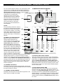
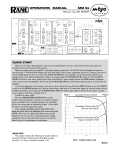
OWNER’S MANUAL
PMX-420
6 Channel Powered Console Mixer
PMX-420
6 Channel Powered Console Mixer
Congratulations on your choice of the NADY AUDIO PMX-420
powered console mixer — you have purchased one of the finest
powered mixing units on the market today. This unit was
developed using the expertise of professional sound engineers
and working musicians. You will find that your new PMX-420
powered mixer has superior performance and greater flexibility
than any other powered mixer in its price range. Please read this
manual carefully to get the most out of your new unit. Thanks for
selecting NADY AUDIO as your choice in powered mixers
F E AT U R E S
• This amazingly compact 6-channel powered mixer can pump
out 420W RMS, complete with Echo Effects and Submixes,
while capable of handling 11 total inputs simultaneously!
• 2 Mono channels each with balanced XLR Mic and 1/4" TRS
line inputs and 2 Stereo channels with input A or B selector
switch for each channel, Effects Return and Submix 1 & 2
Return with dedicated Volume/Pan for a total of 11
simultaneous inputs
• Power Output – 2 x 210W RMS @ 4 ohms (1% THD) with both
channels driven. Advanced amplifier design features include
fan cooling, short circuit protection, speaker DC protection
circuits, clip indicators for utmost safety and reliability and
power ON/OFF anti-thump circuit for quietest operation
• Stereo L-R Master Mix and S1-2 Group Submix buses, with 4
master faders and submix to main enable switch and Pan
controls
• Built-in Echo Effects 32-bit DSP emulates plate, gate, room,
hall, and stadium reverb
• Full complement of input controls, connections and indicators:
Channel Trim controls, Peak LED’s, High, Mid, and Low EQ’s;
Channel Submix assign and PFL buttons, EFF Send controls,
Pan and Volume controls
• Effects Send and Return with level control; 2 X 5-segment LED
display bargraph meters with L-R/S1-2/EFF and PFL selector
and Power Amp peak indicator
• Output insert jacks on all L-R and Submix outputs for adding
effects or compression before the amplifier
• Stereo headphone output with L-R/G1-2/PFL selector and
separate volume adjust
• Outputs include Line Level Left and Right, Submix 1-2, Low
Frequency output, and 1/4" Speaker outputs for Left and Right
• Internal shielded AC supply with 115V(60Hz)/230V(50Hz)
select switch
• Dimension & Weight: 4.5” x 11.4” x 12.3" (114 x 290 x
312mm); 18.8 lbs. (8.5 Kg)
CONTENTS
FEATURES ................................................................................2
Date of Purchase
WARNING ..................................................................................3
INSTALLATION ..........................................................................4
Dealer’s Name
1. Inspection ..............................................................................4
City
2. Setup and Operation ............................................................4
CONTROLS AND CONNECTIONS ............................................5
State
1. Channel Section ....................................................................5
Zip
2. Master and Effects Section ....................................................6
3. Master Input / Output Section ................................................7
Model #
4. Rear Panel..............................................................................8
Serial #
CONNECTIONS ........................................................................9
BLOCK DIAGRAM ....................................................................10
SPECIFICATIONS ....................................................................11
2
WA R N I N G
IMPORTANT SAFETY INSTRUCTIONS
When using this electronic device, basic precautions should always be taken, including the following:
1. Read all instructions before using the product.
2. Do not use this product near water (e.g., near a bathtub, washbowl, kitchen sink, in a wet basement, or near a
swimming pool, etc.).
3. This product should be used only with a cart or stand that will keep it level and stable and prevent wobbling.
4. This product, in combination with headphones or speakers, may be capable of producing sound levels that
could cause permanent hearing loss. Do not operate for a long period of time at a high volume level or at a
level that is uncomfortable. If you experience any hearing loss or ringing in the ears, you should consult an
audiologist.
5. The product should be positioned so that proper ventilation is maintained.
6. The product should be located away from heat sources such as radiators, heat vents, or other devices
(including amplifiers) that produce heat.
7. The product should be connected to a power supply only of the type described in the operating instructions or
as marked on the product. Replace the fuse only with one of the specified type, size, and correct rating.
8. The power supply cord should: (1) be undamaged, (2) never share an outlet or extension cord with other
devices so that the outlet’s or extension cord’s power rating is exceeded, and (3) never be left plugged into
the outlet when not being used for a long period of time.
9. Care should be taken so that objects do not fall into, and liquids are not spilled through, the enclosure’s
openings.
10. The product should be serviced by qualified service personnel if:
A.
The power supply cord or the plug has been damaged.
B. Objects have fallen into, or liquid has been spilled onto the product.
C. The product has been exposed to rain.
D. The product does not appear to operate normally or exhibits a marked change in performance.
E. The product has been dropped, or the enclosure damaged.
11. Do not attempt to service the product beyond what is described in the user maintenance instructions. All
other servicing should be referred to qualified service personnel.
3
I N S TA L L AT I O N
To ensure years of enjoyment from your NADY AUDIO PMX-420, please read and understand this manual thoroughly before
using the unit.
INSPECTION
Your NADY AUDIO PMX-420 powered mixer was carefully packed at the factory in packaging designed to protect the
units in shipment. Before installing and using your unit, carefully examine the packaging and all contents for any signs of
physical damage that may have occurred in transit.
[Please note: Nady Systems is not responsible for shipping damage. If your unit is damaged, do not return to Nady, but
notify your dealer and the shipping company (if shipped to you) immediately to make a claim. Such claims must be made
by the consignee in a timely manner.]
SETUP AND OPERATION
Parts of the unit can become very warm during use. This is normal during operation. Care should be taken to ensure that
there is enough space around the unit for cooling. Also, do not place the PMX-420 powered mixer on high temperature
devices such as power amplifiers, etc., or the unit may overheat in operation.
Although the unit’s chassis is shielded against radio frequency (RF) and electromagnetic interference (EMI), extremely
high fields of RF and EMI should be avoided.
Please make sure that the power unit supplied is marked for the correct voltage in your area (120VAC/60 Hz or
230VAC/50 Hz). Power requirements for electrical equipment differ from area to area. In new installations and portable
sound systems, or any situation in which the AC power is in question, it is wise to confirm the voltage and use the
appropriate power supply unit before connecting it to power sources.
Europe (except UK): 230V, 50Hz
UK and Australia: 240V, 50Hz
USA and Canada: 120V, 60 Hz
For other areas, please check with local authorities.
When ready to operate, plug the AC cord into the power source. Make sure that the unit is turned off before connecting to
the AC power source to avoid possible loud transients which can damage your speakers or your ears. Set the Channel
(11), Submix (16), and Master Stereo Volume Faders (19) to minimum to further reduce the chance of undesired noise
when first powering up. Turn on your PMX-420 powered mixer by pressing on the rear panel Power On/Off Switch (35).
4
CONTROLS AND CONNECTIONS
(5) CHANNEL PEAK LED
The Peak LED illuminates when
a channel input is overloading.
(5)
It detects the peak level after
the Equalizer Controls (6) and
(4)
will light just before clipping to
warn that the signal is
approaching overload. You do
not want the Peak LED to light
except very intermittently. If it
lights persistently, reduce the
Gain Control (4). If the Gain
control is set to minimum, the
(6)
output level of the preceding
equipment should be lowered.
(2)
(1)
(3)
(6) EQUALIZER CONTROLS
All channels are fitted with a
three-band EQ - High, Mid and
Low controls. All three bands
have up to 15 dB of cut and
boost, with a center detent for
(7)
OFF. The frequency response is
flat when all three EQ knobs
are in the center detent
position. The High and Low
(8)
shelving controls have their
frequencies fixed at 12 KHz and
100Hz respectively and the Mid (9)
control is fixed for peak
response at 1KHz. The
channel EQ is a valuable
(11)
feature of the mixer as it allows
the user to control the tonal
characteristics of each channel (10)
separately. For example,
boosting the Low can fatten the
sound, add bass to vocals, or
extra punch to bass, drums and synths.
The Mid control can be used to increase midrange, fatten
guitars, or bring warmth to vocals. Adjusting the High control
can provide a crisp sounding high end. Another very important,
yet often overlooked technique is to use the EQ to subtract
from the mix. Cutting the High control can reduce unwanted
sibilance, hiss, cymbals, or high frequency feedback, while
attenuating the Mid or Low can also eliminate feedback or clear
up a muddy sounding mix. The Mid Freq control can also be
used to reduce any feedback. Cutting the High and Low, then
pushing up the Channel Volume Control (11) is equivalent to
mid range boost!
(1) CHANNEL 1 & 2 INPUTS
These electronically balanced XLR inputs are designed to
accept signals from any balanced or unbalanced low
impedance (Low Z) microphone. They can also be used to
accept line level signals when the Gain is turned close to
minimum. The XLR jack is configured: Pin1 = ground, Pin 2 =
positive (+), Pin 3 = negative (-).
The 1/4” unbalanced inputs are designed to accept unbalanced
Mic or Line level signals such as those from keyboards, drum
machines, or samplers. It will be necessary to adjust the input
Gain Control (4) to achieve a nominal operating level with no
clipping. The Gain Control should be set closer to minimum
when using Line level input signals. All four inputs can be used
simultaneously to accommodate the use of four audio sources.
(2) CHANNEL 3/4 & 5/6 STEREO INPUTS
These 1/4” and RCA unbalanced inputs are designed to accept
line level signals (max 1V / 2.3dBm) such as those common to
CD/tape players, keyboards, direct outputs and home stereo or
DJ equipment.
Channel 3/4 1/4” inputs can also be used as standard mono
line inputs by plugging into the L input only. This signal will be
routed equally to the Pan control and the left and right outputs
in the same way as the standard line input channels.
For each channel there are separate A and B stereo inputs.
Either A or B inputs can be selected using the Input Selector
Switch. This allows the user to switch to a different input
source instantaneously. This is very helpful for DJ when
switching to different source material or for musicians who
change instruments.
(3) INPUT SELECTOR BUTTONS
These select either A or B input sources for channels 3/4 and
5/6.
[Note: Always reset a channel’s input Gain Control (4) after
altering the amount of equalization to avoid input overload.]
The key to successful equalization is to avoid excess. Too
much equalization on the input channels will result in a mix that
is smeared together with nothing specifically defined. During
rehearsals, experiment with the equalizer controls on various
instruments, vocals and combinations of these mixed together
to become familiar with various equalizer settings.
(4) GAIN CONTROL
The Gain control adjusts the input sensitivity (channel gain) of
the inputs. This control can be adjusted to accommodate input
signals from a wide variety of sources, from the high outputs of
keyboards and drum machines to the small signal outputs of
microphones. The best balance of S/N and dynamic range will
be achieved if you adjust the Gain control on each channel
separately so that the Channel Peak LED (5) almost lights.
(7) EFFECTS SEND CONTROL
This control adjusts the level of signal sent to the Effects Send
5
CONTROLS AND CONNECTIONS
2. MASTER AND EFFECTS SECTION
(23)
(24)
(13)
bus or the internal DSP Echo Effects. The channel Effects Send
control is mono, post-EQ, and post-Ch Volume meaning the
signal level sent to the Effects Send bus will be affected by the
Channel Volume Control (11) setting. For almost all effects
send purposes, post-volume is desirable
so that when a Ch Volume level is
adjusted, any reverb send from that
channel follows the volume. Otherwise,
when the volume is turned down, the
(14)
reverb from that channel would still be
audible. You can also use this effect
send to feed inputs of a multi-track
recorder or any other unbalanced line
level application.
(21)
(8) PAN
The channel Pan positions the output of
the channel in the left/right stereo field of
the Master mix and also pans between (12)
S1 and S2 in the Submix. Its constantpower design ensures there are no level
discrepancies whether a signal is hardpanned, center-stage, or somewhere in- (15)
between.
(20)
(22)
(18)
(17)
(16)
(9) SUBMIX 1 & 2 SELECT BUTTON
When the Channel S1/S2 button is
(8)
selected (button depressed), the
channel signal is fed to the Submix 1 &
2 bus, controlled by the Submix 1 & 2
(9)
Volume Faders (16), as well as the
Main Left and Right bus. This signal is
post channel Volume and the placement
between Sub 1 and Sub 2 is adjusted by (11)
the Pan control. The Submix bus offers
you a second stereo submix with its own
(10)
stereo Sub 1 and Sub 2 master faders
and Sub outputs. The Submix can be
used as a mixing aid both live and in the
studio; for example, to combine certain
signals to send to a monitor feed, external power amp, or to an
external effects processor. It can also be used as a stereo
headphone mix if faders are desired for controlling headphone
volume. Using the Submix 1 & 2 Send/Return Inserts (29), the
Sub signal can be sent out to an external effects processor and
then returned into the mixer and mixed onto the Main Left and
Right bus allowing these more sensitive faders to adjust the
returned signal level.
(19)
(12) EFFECTS SEND LEVEL CONTROL
This control adjusts the final mixed level of the channel Effects
Send signals. This signal is then sent to either the internal Echo
Effects DSP or the Effects Send Output (27). Plugging into
either the Effects Send Output (27) or Effects Return Input
(28) jack will automatically disable the internal Echo Effects. The
Effects Send signal can be output to an effects processor, multitrack recorder, or used for any other line-level auxiliary purpose,
such as monitor feeds.
(10) CHANNEL PFL BUTTON
This button sends the pre-volume channel signal to the PFL bus
for monitoring the input signal with headphones before increasing
the channel volume into the mix.
(13) ECHO EFFECTS DELAY TIME
This rotary wheel can be used to select one of 16 preset time
intervals of the built-in Echo Effects DSP between settings 0 - F
as shown on the Echo Effects Display (14). Setting 0 - 2 selects
the shortest echo time to emulate plate and doubling effects
whereas settings 7 - F enables the longest echo time for stadium
reverbs and delay sounds. Settings around 3 - 6 emulate room
and hall reverbs by adjusting the Repeat Control (15) to approx
ten o’clock.
(11) CHANNEL VOLUME CONTROL
This adjusts the volume level of each channel signal sent to the
Effects, Submix, and Main Left & Right.
6
CONTROLS AND CONNECTIONS
can be used to maintain proper levels. When set to Main Left &
Right, the top red Peak LED will light when the powered output
signal is just below clipping. It is acceptable if the red LED lights
occasionally. If the red LED lights more than occasionally, you
should turn down the Main Left & Right Volume Faders (19) to
avoid audible distortion and clipping, which can cause damage to
your speakers and even the internal amplifier.
(14) ECHO EFFECTS DISPLAY
This numeric LED display will indicate which of the 16 echo
presets has been selected (0 - F).
(15) ECHO EFFECTS REPEAT CONTROL
This control adjusts the number of repeats and feedback/depth of
the echo effect. Turning the control clockwise sets the repeats to
maximum for lengthy stadium echoes or plate effects. Turning the
control counter-clockwise sets less repeats for doubling effects.
[Caution: Prolonged use at levels above clipping can cause
damage to your speakers and even the internal amplifier.
Carefully monitor the bargraph meter to avoid prolonged
clipping.]
The Effects Channel Pan Control (8), Submix 1 & 2 Select
Button (9), PFL Button (10), and Channel Volume Control (11)
all operate same as the other channels on the internal Echo
Effects signal or the Effects Return signal.
(22) HEADPHONE SELECT SWITCH
This switch is used to set which signal will be sent to the
Headphones Output (26). Main Stereo Left & Right signals are
sent when set to L - R. When set to S1 - S2, Submix 1 is heard
on the left and Submix 2 on the right. The signal of any channel
with its PFL Button depressed is heard when the switch is set to
PFL.
(16) SUBMIX 1 & 2 VOLUME FADERS
These faders adjust the level of the Submix 1 & 2 signals that are
sent to the Submix 1 & 2 Outputs (30). These faders are post
Submix 1 & 2 Send/Return Inserts (29) and will control any
signal returning to the PMX-420 via those jacks. The Submix
signal can also be selected for the Headphone Output (26) for
easy monitoring. The Submix can be a very useful feature if
used effectively The Submix can be used as a mixing aid both
live and in the studio; for example, to combine certain signals to
send to a monitor feed, external power amp, or to an external
effects processor. This submix can also be added to the
Main/Master mix by depressing the Submix to L-R
Enable Buttons (17).
(23) POWER LED
This LED will illuminate when the unit is switched on.
(24) PFL LED
This LED will illuminate when any one of the Channel PFL
Buttons (10) are switched on.
3. MASTER INPUT / OUTPUT SECTION
(30)
(32)
(33)
(34)
(35)
(17) SUBMIX TO L-R ENABLE BUTTONS
When these push-button switches are depressed,
the Submix signal is added to the Main/Master bus
via the Pan controls.
(27)
(18) SUBMIX TO L-R PAN CONTROLS
With the Submix to L-R Buttons (17) enabled, the
Submix can be panned on to the Main Left & Right
bus using these controls
(19) MAIN LEFT & RIGHT VOLUME FADERS
These adjust the final level of the Master Left &
Right signals, that are sent to the Main Left &
Right (32), Record (34), Low-Pass (33),
Headphone (26), and Speaker Stereo Outputs
(36). These faders are post Main Left & Right
Send/Return Inserts (31) and will affect any signal
returning to the PMX-420 via those jacks.
(28)
(29)
(20) LED LEVEL SELECT SWITCH
This switch is used to select which signals will illuminate the Dual
LED Bargraph Meter (21). Main Stereo Left & Right signals are
displayed when set to L - R. When set to S1 - S2, Submix 1 is
displayed on the left and Submix 2 is displayed on the right.
When set to Effects - PFL, the effects level is displayed on the
left bargraph and the PFL level is displayed on the right
bargraph.
(31)
(25)
(26)
(25) HEADPHONE CONTROL
The volume control adjusts the level of the Headphone Output
(26). The Headphone Select Switch (22) determines which
signal is heard.
(26) HEADPHONE OUTPUT
The Headphone 1/4” stereo output can be used to monitor the
Main, Submix, or PFL signals. Capable of powering headphones
with impedances of 8 ohms or greater
(21) DUAL LED BARGRAPH METER
These 5-stage dual LED meters will display the relative output
level of either the Main Left and Right, Submix 1 & 2, or Effects
and PFL signals depending on the LED Level Select switch. They
(27) EFFECTS SEND OUTPUT
7
CONTROLS AND CONNECTIONS
4. REAR PANEL
This mono unbalanced 1/4” jack outputs the channel signals
which can be adjusted by the Effects Send Controls (7 & 12).
(36)
(28) EFFECTS RETURN INPUT
This mono unbalanced 1/4” jack enables convenient inputs to the
Effects Channel. If you connect a signal to the return jacks, the
signal will be routed to the effects Channel Volume Control
(11).
Plugging into either the Effects Send Output (27) or Effects
Return Input (28) jacks will automatically disable the internal
Echo Effects.
(29) SUBMIX 1 & 2 SEND/RETURN INSERTS
These 1/4” TRS insert jacks can be used to send out the Submix
signals to an external device and return the signals back via the
same jack. They are pre-Sub 1 & 2 fader and allow for routing
the signal through external devices such as equalizers,
compressors, or effects units. Insert cables must be used for
these connections. The wiring for the insert jacks is Tip = Send,
Insert Cable
Ring = Return.
Tip = Send
Send
(37)
(38)
(39)
(35) POWER ON/OFF SWITCH
Use this rocker switch to turn the unit on and off.
Ring = Return
(36) STEREO SPEAKER OUTPUTS
These Left & Right 1/4” speaker outputs can each deliver up to
210W RMS to 4 ohms loads or 150W RMS to 8 ohms loads with
both channels driven simultaneously.
Return
(30) SUBMIX 1 & 2 OUTPUTS
These 1/4” jacks output the Submix 1 & 2 unbalanced line level
signals.
[Caution: Make sure that the speaker, connectors and wiring
can handle the rated output power to avoid damage. Note that
prolonged use at levels above clipping can drive the amplifier
into thermal runaway and damage the internal amplifier and
speaker, so care must be taken to not overload the amplifier.
Never use less than 4 ohms total impedance for either channel
as this can also cause the amplifier to overheat and create
thermal runaway.]
(31) MAIN LEFT & RIGHT SEND/RETURN INSERTS
These 1/4” TRS insert jacks can be used to send out the Main
Left & Right signals to an external device and return the signals
via the same jack. They are pre-Main Left & Right Volume fader
and allow for routing the signal through external devices such as
equalizers, compressors, or effects units. Insert cables must be
used for these connections. The wiring for the insert jacks is Tip
= Send, Ring = Return.
(37) POWER CONNECTOR
The IEC jack is used to connect the power cord to the AC Power
Source.
(32) MAIN LEFT & RIGHT OUTPUTS
These 1/4” jacks output unbalanced line level signals from the
Main Left and Right volume faders.
[Caution: Never remove the center grounding pin as this can
cause a serious safety hazard and will immediately void your
warranty.]
(33) LOW-PASS LEFT & RIGHT OUTPUTS
These 1/4” jacks output unbalanced line level signals that have
been filtered through a Low Pass filter. This output is perfect for
feeding directly to an amplifier that powers a subwoofer speaker
or to a powered subwoofer with no crossover necessary. The
frequency response is 30Hz - 150Hz (-6dB) with a -12dB roll-off
point at 250Hz. These signals are post Main Left & Right faders.
(38) FUSE COMPARTMENT
Replace with only the same type fuse. If the fuse blows
continuously, have the unit serviced by qualified personnel. The
PMX-420 powered mixer uses 20mm glass tube Fast Blow
fuses: 5A 250V for 115VAC, 2.5A 250V for 230VAC.
(39) AC VOLTAGE SELECTOR SWITCH
Before plugging in the power cord, check to see that the unit is
set for the proper voltage for your area: ~115V (60Hz) or ~230V
(50Hz).
(34) RECORD LEFT & RIGHT OUTPUTS
These 1/4” jacks output unbalanced line level signals from the
Left and Right bus. These signals are pre Main Left & Right
faders.
8
CONNECTIONS
8Ω
8Ω
8Ω
8Ω
MONITOR
SPEAKERS &
POWER AMP
REVERB / EFX
REVERB / EFX
CD
PLAYER
POWERED SUB
TAPE/CD/MP-3 PLAYER
PA or RECORDING
DEVICE
PA or RECORDING
DEVICE
COMPRESSOR
9
BLOCK DIAGRAM
10
S P E C I F I C AT I O N S
1. INPUTS
Input
CHANNEL 1-2
CHANNEL 1-2
CHANNEL 3-4 Mono
CHANNEL 3-6 STEREO
EFFECTS RETURN
SUB INSERT RETURNS
MAIN INSERT RETURNS
Connector
Impedance
XLR BALANCED
1/4” UNBALANCED
1/4” UNBALANCED
1/4” & RCA UNBALANCED
1/4” UNBALANCED
1/4” UNBALANCED RING
1/4” UNBALANCED RING
Sensitivity
10KΩ
5KΩ
4KΩ
8KΩ
22KΩ
7KΩ
5KΩ
-60 dBm / 0.7mV
-54 dBm / 1.4mV
-32 dBm / 20mV
-32 dBm / 20mV
-27 dBm / 33mV
-10 dBm / 240mV
0 dBm / 0.775mV
Max Level
0 dBm / 0.775V
+4 dBm / 1.2V
+2 dBm / 1V
+2 dBm / 1V
+2 dBm / 1V
+5 dBm / 1.4V
+5 dBm / 1.4V
Sensitivity measured for max power with all volumes at max, EQ’s at mid
Maximum Input Level measured with Gain set to min
2. MIXER SECTION
Channel High EQ +/-15dB ................................................................................................................................................................12KHz, Rotary control
Channel Mid EQ +/-15dB ....................................................................................................................................................................1KHz, Rotary control
Channel Low EQ +/-15dB ..................................................................................................................................................................100Hz, Rotary control
Channel Gain, Effects Send, Pan, Volume ..................................................................................................................................................Rotary controls
PFL, S1-2 Select ................................................................................................................................................................................Push-button switches
Echo Effect Time Delay (0 - F) ............................................................................................................................................................6 presets 20-350mS
Master and Submix dual faders ...............................................................................................................................................-∞ to +10dB, 50mm sliders
3. MASTER OUTPUT SECTION
Channel Input to Main Output
Frequency Response........................................................................................................................................................................20Hz~25KHz (+/- 3dB)
THD + Noise................................................................................................................................................................................................................0.08%
S/N Ratio ........................................................................................................................................................-80dB (gain controls @ mid, faders at 0dB)
Noise Floor ......................................................................................................................................................550uV (gain controls @ mid, faders at 0dB)
Total Gain. ....................................................................................................................................................................................................................60dB
Output
Connector
Impedance
Max Level
EFFECTS SEND
SUBMIX INSERT SEND
SUBMIX 1-2
MAIN L-R INSERT SEND
MAIN L-R
RECORD L-R
LOW PASS L-R30Hz-150Hz
1/4” UNBALANCED
1/4” UNBALANCED TIP
1/4” UNBALANCED
1/4” UNBALANCED TIP
1/4” UNBALANCED
1/4” UNBALANCED
1/4” UNBALANCED
1.5KΩ
150Ω
150Ω
150Ω
200Ω
150Ω
150Ω
+16dBm / 5V
+10dBm / 2.4V
+12Bm / 3V
+12Bm / 3V
+16dBm / 5V
+12Bm / 3V
+12Bm / 3V
HEADPHONE (w/32Ω load)
1/4” TRS STEREO
32Ω
2 x 20mW
4. POWER OUTPUT SECTION
Power Output
8Ω Both Channels Driven (1% THD) ..............................................................................................................................................150W RMS per side
4Ω Both Channels Driven (1% THD) ..............................................................................................................................................210W RMS per side
Channel Input to Speaker Output
Frequency Response ..................................................................................................................................................................20Hz~22KHz (+/- 3dB)
THD........................................................................................................................................................................................................................0.07%
S/N Ratio ........................................................................................................................................................-74dB (gain controls @ mid, faders at 0)
Noise Floor ....................................................................................................................................................6.2mV (gain controls @ mid, faders at 0)
Total Gain ................................................................................................................................................................................................................94dB
Amplifier Protection ............................................Fan cooling, short circuit protection, DC protection circuits, clip LED indicators, Power ON/OFF relays
5. GENERAL
Power Requirements ..........................................................................................................................Voltage selectable, 115VAC/60Hz or 230VAC /50Hz
Fuse Requirements ......................................................................................................................................5x20mm glass tube F.B. 5A 250V @ 115VAC
2.5A 250V @ 230VAC
Weight ...................................................................................................................................................................................................... 18.8 lbs. (8.5 Kg)
Dimensions (HWD) ..............................................................................................................................................4.5” x 11.4” x 12.3” (114 x 290 x 312mm)
The specifications above are correct at the time of printing of this manual. For improvement purposes, all specifications for this unit, including design
and appearance, are subject to change without prior notice.
11
SERVICE FOR YOUR NADY AUDIO PRODUCT
(U.S.) Should your NADY AUDIO product require service, please contact the Nady Service Department via
telephone at (510) 652-2411, or e-mail at [email protected].
(International) For service, please contact the NADY AUDIO distributor in your country through the dealer from
whom you purchased this product.
DO NOT ATTEMPT TO SERVICE THIS UNIT
YOURSELF AS IT CAN BE DANGEROUS
AND WILL ALSO VOID THE WARRANTY.
NADY SYSTEMS, INC. • 6701 SHELLMOUND STREET, EMERYVILLE, CA 94608
Tel: 510.652.2411 • Fax: 510.652.5075 • nady.com