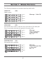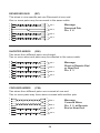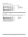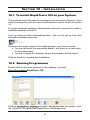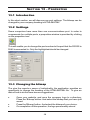
1
RapidTrace 700 User Guide Issue 1.0 TABLE OF CONTENTS SECTION 1 1.1 INTRODUCTION Receiving Shipment ...................................................6 SECTION 2 2.1 2.2 PRODUCT FEATURES Description ............................................................7 RapidTrace 700 Features ..........................................7 SECTION 3 SPECIFICATIONS SECTION 4 4.1 4.2 4.3 4.4 4.5 4.6 4.7 4.8 4.9 4.10 4.11 FIRST OPERATIONS Preparing RapidTrace 700 For Use ...........................11 Menu Architecture ......................................................12 Selecting Language ...................................................13 Set Unit Of Measure ..................................................13 Set Time And Date .....................................................13 Select Wiring Type .....................................................13 Set Volocity Of Propogation .......................................13 Adjusting Contrast .....................................................14 Setting Auto Shutdown ..............................................14 Address Settings ........................................................14 Volocity Of Propogation .............................................15 SECTION 5 5.1 5.2 5.3 5.4 5.5 5.5.1 5.5.2 5.5.3 5.5.4 5.6 5.7 5.8 USING THE RapidTrace 700 T.N.V. (Telecom Network Voltage) .............................16 Services Detection .....................................................17 General Operation .....................................................17 Test Pass Screen .......................................................19 Test Failed Screen .....................................................20 Open And Short Fault ................................................20 Reversed And Split Pair Fault ....................................21 Multipul Faults ............................................................22 Missing Remote .........................................................22 Cable Length Measurement ......................................23 Tone Generator ..........................................................24 Backlight ............................................................24 TABLE OF CONTENTS SECTION 6 6.1 6.2 6.3 6.4 DOWNLOADING TO P.C. Linking RapidTrace 700 To PC ....................................25 Selective Download ...................................................25 Full Download ............................................................25 Erasing Memory .........................................................26 SECTION 7 WIRING PROTOCOLS SECTION 8 MAINTENANCE SECTION 9 9.1 9.2 RapidTrace 700 SOFTWARE Introduction ............................................................31 Requirements ............................................................31 Section 10 10.1 10.2 INSTALLATION Installation ............................................................32 Program running ..........................................................32 Section 11 11.1 11.2 USING THE APPLICATION Introduction ............................................................33 Downloading Results to PC .......................................33 Section 12 12.1 12.2 12.3 SAVING RESULTS TO HTML/MHTML Sending file electronically ............................................35 Opening file to print .....................................................36 Using job and customer button ..................................37 Section 13 13.1 13.2 13.3 PROPERTIES Introduction ............................................................38 Settings ............................................................38 Changing the bit map .................................................38 Section 13 TROUBLESHOOTING AND FREQUENTLY ASKED QUESTION SECTION 1 - INTRODUCTION Warning ● This instrument meets the safety requirements of IEC61010-1: 1995. ● The RapidTrace 700 is designed for use on de-energized circuits only. ● Connection to line voltages will damage the instrument and could be hazardous to the operator. ● This instrument is protected against connection to telecom network voltages according to EN61326-1. ● Safety is the responsibility of the operator. International Electrical Symbols This symbol signifies that the instrument is protected by double or reinforced insulation. Use only specified replacement parts when servicing the instrument. This symbol on the instrument indicates a WARNING and that the operator must refer to the user manual for instructions before operating the instrument. In this manual, the symbol preceding instructions indicates that if the instructions are not followed, bodily injury, installation/sample and product damage may result. Risk of electric shock. The voltage at the parts marked with this symbol may be dangerous. 5 1.1 Receiving Your Shipment Upon receiving your shipment, make sure that the contents are consistent with the packing list. Notify your distributor of any missing items. If the equipment appears to be damaged, file a claim immediately with the carrier and notify your distributor at once, giving a detailed description of any damage. 6 SECTION 2 - PRODUCT FEATURES 2.1 Description The RapidTrace 700, is a hand held structured cabling tester and trouble shooter, designed for use on screened and unscreened cables. Fitted with RJ45 connectors and wired to either TIA568 A/B, U.S.O.C or I.S.D.N standards. It will store up to 1,000 test results for downloading to P.C to produce an installation test report, showing time and date of test, wiring standard, installed cable length, pass/fail result and location of site tested. All test results for display textually and graphically along with cable length, wiring standard, V.P, an outlet address and smart remote ID number, audible pass/fail tone is emitted by the main unit with a red/green pass/fail LED on the remote unit. When plugged into an active port it will emit an audible tone if telephone voltages are present on any of the pins and will identify 10 base T. Token Ring and 100 Mbit connections and inhibit testing, in the presence of live circuits an inbuilt tone generator can be selected for cable tracing. Features: ! Stores up to 1,000 test results ! Complete with software for download to PC and generating test reports ! ! ! ! Rugged case design rated to IP54 Scratch resistant front screen 128x64 Electro luminescent backlit display Detects open circuits, shorts, crossed wires, crossed pairs, reversed pairs, split pairs and screen faults ! Measures length of all 4 pairs and indicates distance to fault ! Tone generator for cable tracing ! Supports up to 16 uniquely numbered smart remote units 7 2.2 RapidTrace 700 Features 1 03:11:05 18:24 RapidTrace 700 2 TIA568 STP Vp=79% 3 4 1 5 6 7 8 10 9 1 2 3 4 5 6 7 8 9 10 RJ45 Input connector Graphical L.C.D Service button Length test button Wire map test button Address settings Back light button Power on/off button Remote ID button Pass/fail test BI colour L.E.D Buttons 3 to 6 have the following functions, when menu is selected 5-To scroll cursor arrow 3-To increment setting 4-To decrement setting 6-Return to menu 8 SECTION 3 - SPECIFICATIONS Range: 500 ft (150m) Accuracy: ±5% Cable Types: UTP, STP, FTP & SSTP Faults Indicated: Short Circuit Pair Open Circuit Wire Short Between Pairs Split / Cross Pairs Pair Reversals Shield Continuity Fault Location: Near End, Remote End, or distance if midway Wiring Schemes: TIA 568A/B, USOC & ISDN Service Indication: Telephone, 10BaseT, 100Mbit+, Token Ring Voltage Warning: Warns of TNV (Telecom Network Voltage) presence Test Inhibit: Inhibits Testing in the presence of live voltages Tone Generator: Tone generator (oscillating) 810Hz - 1110Hz Battery indicator: “Gas Gauge” Bargraph Main Unit Display: 128 x 64 pixel Graphical LCD Fault Display: All fault and setting info displayed textually and graphically Display Backlight: Electroluminescent Remote Display: Green/Red LED Languages: English (USA and UK), German, French, Spanish, Portuguese, Italian Power Supply: 4 x 1.5V AA alkaline batteries Auto Power Off: Selectable, disabled 1, 2, 3 minutes or disabled 9 Battery Life: Standby mode >4000hrs Continuous testing >7.5hrs Storage Temperature: -20 to 70°C (-4 to 158°F) 5 to 95% RH non-condensing Operating Temperature: 0 to 40°C (32 to 112°F) 5 to 95% RH non-condensing Main Unit Weight: 350g (12 oz) Main Unit Dimensions: 165 x 90 x 37mm (6.5 x 3.5 x 1.5”) Remote Weight: 40g (1.5 oz) Remote Dimensions: 65 x 52 x 25mm (2.5 x 2.0 x 1.0”) Safety: IEC61010-1 EMC: EN61326-1 CE: Compliant with current EU directives ESD: EN61000-4-2 EM: EN61000-4-3 Burst: EN61000-4-4 Conducted RF: EN61000-4-6 10 SECTION 4 - FIRST OPERATIONS 4.1 Prepairing RapidTrace 700 For Use Press button to power the tester, the following screen will be displayed 03:11:05 18:24 1 2 RapidTrace 700 3 TIA568 STP Vp=79% 5 1 2 3 4 5 6 4 000 6 Time in 24 hour clock Date DAY:MONTH:YEAR Wiring Configuration V.P (Velocity of propogation) Battery condition Indicator Number of test results stored (max 1,000) The following parameters will need to be set prior to use (refer to 4.2 for menu locations) 1-2 The RapidTrace 700 time and date is set at G.M.T (Grenwich Mean Time). Prior to use the RapidTrace 700 may need to be reset to “local time”, during the course of the year, it will need to be reset for day light saving To change Time/Date see section 4.3 3 Wiring configuration see section 4.4 4 Set velocity of propogation for cable type and manufacturer see section 4.5 and 4.11 5 Set address settings see section 4.6 11 4.2 Menu Achitecture Level 1 03:11:05 18:24 RapidTrace 700 TIA568 To access level 2 menu press down then press then release both buttons STP Vp=79% 000 18:24 Level 2 03:11:05 Type = tia568 stp warble tone Vp=79% contrast system settings erase memory pc link 000 18:24 address settings set time shutdown: disable metres eng (uk) 03:11:05 Level 3 000 18:24 03:11:05 you are about to erase the memory. do you want to continue? No 18:24 18:24 00000 ^ selective download full download 03:11:05 hours minutes day month year 18:24 yes 03:11:05 18 24 03 11 2005 000 03:11:05 address settings 92111/0004 ^ Level 4 12 4.3 Set Language 18:24 03:11:05 address settings set time shutdown: disable metres eng (uk) 000 Menu Level 4 Press to move to display language. Press S or L to change between English (UK or USA), French, German, Italian, Spanish or Portugese. Press to return to menu 4.4 Unit of Measure 18:24 03:11:05 address settings set time shutdown: disable metres eng (uk) Menu Level 3 Press to move to displayed unit. Press S or L to change. Select for feet or meters, press to return to menu 000 4.5 Set Time and Date 18:24 hours minutes day month year 18 24 03 11 2005 03:11:05 Menu Level 4 Press to move to desired position. Press and to incremen or decrement. When time and date are set correctly press to return to menu 000 4.6 Set Wiring Type 18:24 03:11:05 Type = tia568 stp warble tone Vp=79% contrast system settings erase memory pc link 000 Menu Level 2 Press to move to type. Press or to select type "TIA568 UTP, USOC STP, USOC UTP, ISDN, when desired type is displayed, press to return to menu 4.7 Set Velocity of Propogation (VP) 18:24 03:11:05 Type = tia568 stp warble tone Vp=79% contrast system settings erase memory pc link 000 Menu Level 2 Press to move to V.P. Press or to increment or decrement value selectable between 50% and 99%, when required value is shown. Press to return to menu. See also section 4.11 13 4.8 Adjust Contrast 18:24 Type = tia568 stp warble tone Vp=79% contrast system settings erase memory pc link 03:11:05 Menu Level 2 Press to move to contrast. Press or to increase or decrease contrast. Press to return to menu 000 4.9 Set Auto Shutdown 18:24 address settings set time shutdown: disable metres eng (uk) 03:11:05 Menu Level 3 Press to move to shutdown. Press or to select between disabled 1, 3, 5 minutes. Press to return to menu 000 4.10 Address Settings Menu Level 4 The RapidTrace 700 will store up to 1,000 test results, each result is stored under a unique 9 character "address", these nine characters are divided into two groups (-----/----). The first comprises of five characters which may be used in a combination of alpha (A-Z) or numeric (0-9) allowing identification of customer, building, floor, number or cabinet etc. The last four characters are numeric only (0-9) for port identification and will automatically increment for each test result saved. The numbering sequence may be commenced at any number within the range 0001 to 9999. During testing the address may be amended prior to saving (see section 5.4(5). The saved test results may be downloaded to PC using the software provided in selective or full download. Selective download will only transfer to PC those results that have been identified by the first five digits of the address. Full download will transfer to PC ALL stored results (refer to section 6) and section (4.10) to set address characters. Procede as follows: 18:24 03:11:05 address settings 92111/0004 ^ Press to move . Press button to decrement and button to increment. Press to return to menu 14 4.11 Velocity of Propogation (VP) Vp, or velocity of propogation, value are characteristic of each cable type and brand. The Vp is used to measure the length of a cable and to measure fault location. The more accurate the Vp, the more accurate the measurement result will be. The Vp figure quoted when used will show a variation in length of each pair, this is caused by different twist ratios and conductor insulation, this difference is known as a skew. See section 5.6 The cable manufacturer may list the Vp on their specification sheet or may be able to provide it when asked. Sometimes this value is not readily available, or the user may wish to determine it specifically to compensate for each cable batch variations, or for special cable applications. This is quite easy: 1. Take a cable sample of exact length increment (ft of m) longer than 60ft (20m) 2. Measure the exact length of the cable using a tape measure 3. Connect one end of the cable to the RapidTrace 700 . Leave the end unterminated and make sure the wires do no short to each other 4. Measure the length and adjust the Vp until the exact length is displayed 5 When the exact length is displayed, Vp is established 15 SECTION 5 - USING 5.1 THE RAPIDTRACE 700 TNV (Telecom Network Voltage) Testing and Warning The RapidTrace 700 is designed to work on nonenergized circuits only. Make sure that the circuit to be tested is not live before mapping. Turn the unit on and plug it into the port to be tested with a patch cord. 03:11:05 18:24 RapidTrace 700 TIA568 STP Vp=79% If a Telecom Network Voltage is present, the unit will give a continuous audible warning, and display the following: !!!! Telephone Voltage detected on Pin X !!!! NOTE: The pin on the RJ45 connection, on which the voltage is detected, is displayed. In the event of a TNV (Telecom Network Voltage) Warning, the unit should immediately be disconnected and testing stopped, since it is not designed for testing on live networks. 16 5.2 Service Detection To detect an active data port, plug the unit into the port to be tested using a short patch cable and press the button. The display will show the type of data connection or service present from the following list: Token Ring 100Mbit+ Unknown Service 5.3 10base T No Service 03:11:05 18:24 RapidTrace 700 TIA568 STP Vp=79% General Operation 03:11:05 18:24 RapidTrace 700 TIA568 STP Vp=79% • Set the instrument to the desired VP and wiring scheme (see section 4.4, 4.5, 4.11). • Make sure no Telecom Network Voltages or other services are detected (see 5.1). • Attach the instrument to one end of the cable to be tested • Attach the remote unit to the other end of the same cable • Press the button. 17 The display will briefly show the following message while testing is being performed: * * * * * * * * * * * * * * * * * * * Test in Progress * * * * * * * * * * * * * * * * * * * This screen is quickly followed by the test results screen. • Test Pass/OK Screen • Test Failed Screen 18 5.4 Test Pass/OK Screen 1 2 4 4 5 ID:1 Pass TIA568 Vp=79% L=103m A2111/0004 No Accept Yes When testing ISDN wiring, any resistive terminators should be switched out of the circuit or disconnected. Failure to do so could lead to erroneous test results. The left side of the display shows information about the test performed and the status of the test result. 1 The first line shows the unique identity of the active remote unit connected to the far end (in this case, ID1). There are 15 additional active remote units available as optional accessories (ID#2 to ID#16). 2 The test status, PASS is indicated on the second line. A test PASS is confirmed by a double beep from the main unit and a double green flash on the LED of the active remote unit. 3 Next, information about the test type selected, along with a measured value of the cable length, and an indication of the current VP setting is displayed. If a fault is found an appropriate message will be displayed, along with a warning tone on the main unit, and a red flashing LED on the remote unit. 4 Shows the address identification which will be stored on acceptance. 5 Gives the option of storing the results under the number shown by pressing the button L or aborting by pressing button . If is pressed the option is given to change the address. 19 5.5 Test Failed Screen 5.5.1 Open and Short Fault In the event of an Open fault, the following is displayed: ID1 FAILED TIA568 L=94ft Vp=71% 4 5 1 2 3 6 7 8 S 4 5 1 2 3 6 7 8 S Open at remote end Pin 7 Notice the word FAILED under the cable ID1 and also the detailed message at the bottom of the display. The graphical portion of the display also shows that the fault is an open on pin 7 at the remote end by showing a break in the line at this point. NOTE: In the event that an open or short circuit fault occurs at either end of a cable or link under test, the unit will show the fault as at the near end or the remote end. These faults are the most common and are mainly due to termination problems. If the fault occurs some way along the cable or link under test, then a display similar to the one shown below will occur. Notice, that on this occasion the actual measured distance to the fault is given. In the event of a Short fault, the following is displayed: ID1 FAILED TIA568 L=94ft Vp=71% 4 5 1 2 3 6 7 8 S 4 5 1 2 3 6 7 8 S Short at 36ft Pin 1 2 In this situation, the graphical portion of the display also shows that the fault is a short between pins 1 and 2 and the short is drawn at an approximation to the distance along the cable or link under test, at which it occurs. 20 5.5.2 Reversed and Split Pair Fault In the event of a Reversed Pair fault, the following is displayed: ID1 FAILED TIA568 L=94ft Vp=71% 4 5 1 2 3 6 7 8 S 4 5 1 2 3 6 7 8 S Reversed Pair Pin 4 5 In the event of a Split Pair fault, the following is displayed: ID1 FAILED TIA568 L=94ft Vp=71% 4 5 1 2 3 6 7 8 S 4 5 1 2 3 6 7 8 S Split Pair Pin 1 2 3 6 NOTE: For cables less than 6 ft (2m) in length the tester is unable to distinguish a Split Pair condition. In this event (cable too short), the following screen is displayed briefly, before the screen to warn the user that a Split Pair test has not been carried out. * * * * * * * * * * * * * * * * * * * Too Short for Split Pair Test * * * * * * * * * * * * * * * * * * * 21 5.5.3 Multiple Faults In the event of a multiple fault, or a cable or link with more than one fault on it, the tester will report the faults in the following order of priority. • Shorts • Reversals • Opens For example, on a cable with an Open on pin 3 and a Short between pins 7 and 8, only the Short in pins 7 and 8 will be reported. 5.5.4 Missing Remote If a wire map test is performed without a remote unit connected at the far end, the following screen will be displayed: 03:11:05 18:24 missing remote unit 22 5.6 Cable Length Measurement 03:11:05 18:24 RapidTrace 700 TIA568 STP Vp=79% The remote unit does not need to be attached for this test to be performed. Although it does not matter if it is attached, any terminators on ISDN wiring or sockets should be switched out of the circuit or disconnected. Attach the main unit to one end of the cable and press the L button. The length of all four pairs in the cable are measured, and the results displayed simultaneously, as shown below. Pr. Pr. Pr. Pr. 4-5 1-2 3-6 7-8 100m 102m ----106m TIA568 UTP Vp=71% In this example, the length of pair 3 - 6 is missing, as there is a fault on the pair which is preventing the TDR circuit from measuring the length. Length will be displayed in the selected units, either meters or feet, and the Vp and cable testing standard will also be displayed. Length measurement accuracy depends on the correct setting of the Vp (Velocity of Propagation) for the cable under test. If the Vp is not known for a particular cable, then a known length of that cable (at least 60ft or 20m long) may be connected to the instrument and the Vp adjusted until the correct length reading is obtained (see 4.11). 23 5.7 Tone Generator The RapidTrace 700 may also be used as a tone generator, to trace and identify cables and wires. The user will need a cable tone tracer. 03:11:05 18:24 RapidTrace 700 TIA568 18:24 STP Vp=79% 03:11:05 Type = tia568 stp warble tone Vp=79% contrast system settings erase memory pc link To select Tone Generator : Menu level 2. Press to move to Warble Tone, press L to select. The warble tone screen will be displayed. To exit press 03:11:05 18:24 warble tone The injected signal oscillates between 810Hz and 1110Hz, six times per second. NOTE: The auto-off function is disabled in Tone Generator mode, so that the tone can be injected into a cable for an extended period of time while tracing takes place. 5.8 Backlight The display backlight is switched on and off with the 24 button. SECTION 6 - DOWNLOADING 6.1 TO PC Linking RapidTrace 700 to PC Prior to commencing the operation, read section 3, using the application. Fit RS232 to RJ45 adaptor into the PC serial port using the longer RJ45 patch lead, plugging one end into the adaptor, the other into the RJ45 input connector on the RapidTrace 700 main unit ENSURE THE PC IS PREPARED AND READY TO ACCEPT TEST RESULTS 6.2 18:24 Selective Download 000000 03:11:05 Press to move cursor and buttons will increment and decrement digits (0-9, A-Z). When the desired combination has been entered press 03:11:05 Press button to move to selective download. Press to commence download. Selective Download Full Download 18:24 y336f Selective Download Full Download 6.3 Menu Level 3 Full Download Follow procedure in 6.1. Press commence download to move to full download, press to For both 6.2 and 6.3, progress of the download may be monitored on the PC. Download time will vary according to the number of results stored 25 6.4 Erasing RapidTrace 700 Memory Menu Level 3 WHEN THIS FUNCTION HAS BEEN COMPLETED, ALL STORED TEST RESULTS WILL BE DELETED. ENSURE RESULTS HAVE BEEN SAVED TO PC OR ARE NO LONGER REQUIRED. ONCE ERASED THEY CANNOT BE RECOVERED 18:24 you are about to erase the memory. do you want to continue? No 03:11:05 Press to erase memory, press to abort, press to return to menu yes 26 SECTION 7 - WIRING PROTOCOL The following drawings are examples depicting cable faults: CABLE OK (OK) Cable is good. 4 4 5 5 3 3 6 6 1 1 2 2 7 7 8 8 OPEN PAIR Pair 1 Message: Cable OK Pair 2 Pair 3 Pair 4 (OP) One specific pair is open. It may be one or two wires in the same pair. One or more pairs may also be opened in the same cable. 4 4 5 5 3 3 6 6 1 1 2 2 7 7 8 8 SHORTED PAIR Pair 1 Pair 2 Pair 3 Message: Open at Near End or Remote End Pin 1 2 Pair 4 (SH) One specific pair is shorted. 4 4 5 5 3 3 6 6 1 1 2 2 7 7 8 8 Pair 1 Pair 2 Pair 3 Pair 4 27 Message: Short at Remote End or Near End Pin 1 2 REVERSED PAIR (RP) The wires in one specific pair are Reversed at one end. One or more pairs may be reversed in the same cable. 4 4 5 5 3 3 6 6 1 1 2 2 7 7 8 8 SHORTED WIRES Pair 1 Pair 2 Message: Reversed Pair Pin 3 6 Pair 3 Pair 4 (SW) Two wires from different pairs are shorted. Two or more wires and pairs may be affected in the same cable. 4 4 5 5 3 3 6 6 1 1 2 2 7 7 8 8 CROSSED WIRES Pair 1 Pair 2 Pair 3 Message: Short at Remote End or Near End Pin 2 3 Pair 4 (CW) Two wires from different pairs are crossed at one end. Two or more pairs may have wires crossed with another pair. 4 4 5 5 3 3 6 6 1 1 2 2 7 7 8 8 Pair 1 Pair 2 Pair 3 Pair 4 28 Message: Crossed Wires Pin 3 5 at Remote End or Near End CROSSED PAIRS (CP) Two pairs are crossed at one end. Two or more pairs may be crossed in the same cable. 4 4 5 5 3 3 6 6 1 1 2 2 7 7 8 8 SPLIT PAIRS Pair 1 Pair 2 Message: Crossed Pairs Pin 1 2 7 8 Pair 3 Pair 4 (SP) One pair uses one wire from another pair. The cable will work, but crosstalk may occur. Two or more pairs in the same cable may be split. 4 4 5 5 3 3 6 6 1 1 2 2 7 7 8 8 Pair 1 Pair 2 Pair 3 Pair 4 29 Message: Split Pairs Pin 2 7 SECTION 8 - MAINTENANCE Use only factory specified replacement parts. Vonaq Ltd will not be held responsible for any accident, incident, or malfunction following a repair done other than by its service centre or by an approved repair centre. 8.1 Changing the Battery Disconnect the instrument from any cable or network link. 1. Turn the instrument OFF. 2. Loosen the 2 screws and remove the battery compartment cover. 3. Replace the batteries with 4 x 1.5V AA alkaline cells, observing the polarities. 4. Reattach the battery compartment cover. 8.2 Cleaning Disconnect the instrument from any source of electricity. 8.3 • Use a soft cloth lightly dampened with soapy water. • Rinse with a damp cloth and then dry with a dry cloth. • Do not splash water directly on the instrument. • Do not use alcohol, solvents or hydrocarbons. Storage If the instrument is not used for a period of more than 60 days, it is recommended to remove the batteries and store them separately. 30 SECTION 9 - RAPIDTRACE 700 SOFTWARE 9.1 Introduction This manual covers all aspects of the application. From installing, configuration and using the application, which, uses HTML/MHTML formatted results. This means that you don’t have the have the latest office. It will run on older internet explorers. The comprehensive addressing system on the RapidTrace 700 can be configured to identify different job or customers. This gives you the ability to store more one than, job or customer on the RapidTrace 700. The address setting on the RapidTrace 700 corresponds to the Port identification on the PC application. 9.2 Requirements Minimum requirements: Processor Pentium 3 500Mhz or AMD K6 equivalent Ram: 64 Mbytes Operating system: windows 98, ME, XP or 2K Other requirements: ! ! ! ! Internet explorer, Mozilla or Netscape navigator Internet explorer can be found at www.microsoft.com/ie Mozilla can be found at www.mozilla.org/products/firefox/ Netscape navigator can be found at browser.netscape.com/ns8/ ! Serial port. 31 SECTION 10 - INSTALLATION 10.1 To install RapidTrace 700 on your System There should not be the need to reconfigure your computer. However: if you need to change the port the manual will describe how to do this in section 14. For some windows system’s administrative access is required in order to install the software on the PC. If set up does not start automatically then, click on the set up icon. And follow the installation process. There are two major steps in the install process, and some choices. You can the enter the ownership detail’s, but there is no real need for this information You can change the directory, where the program will be stored Click on finish to complete the installation 10.2 Running Programmes Double click on the icon shortcut on the desktop, or select Start>Programs>RapidTrace 700 RapidTrace 700 Click on properties> bitmap and select the bitmap that you desire, click Ok. Default C:\Program files\RapidTrace 700\bitmap.bmp 32 SECTION 11 - USING THE APPLICATION 11.1 Introduction This chapter will describe how to use the application. If no results are stored, and download is attempted, the following message may be displayed, “Run Time 9 error” 11.2 Downloading results to PC Ensure the RapidTrace 700 is correctly connected to the PC, see section 6.1 Commence download by clicking onto the upload button then press button L on the RapidTrace 700, see section 6.2 and 6.3 As the records download a progress bar will appear. And disappear, when the download has been completed. The main window will now show the new results. The number of test results received will be shown in the window above the tool bar. RapidTrace 700 BI Communications Innovation through Technology 33 Date when the test was taken Cable VP Port address Wiring type Length to fault Result NB: The Port identification on the PC corresponds to the application address setting on the RapidTrace 700 34 SECTION 12 - SAVING RESULTS TO A HTML/MHTML FILE Change the customer details. And press the ‘Save’ button. This is will open a pop window, where you can select the directory. Choose the place, where you want the file to be stored. This allows you to store anywhere on your computer or your network. 12.1 Sending files electronically You have downloaded your results, and saved them. Now you want to email them to your clients. Select the MHT format. This will embed the image into the page. 35 12.2 Opening a file to print Previous results can be viewed, in a HTML/MHTML viewer, for example: Internet explorer. Press the ‘Open’ button. From here you can select the file and view it. BI Communications Innovation through Technology Pro ST 36 12.3 Using Job and Customer buttons These features are to be used in conjunction with the RapidTrace 700. Addressing by job Depending which way you have configured your RapidTrace 700, this will determine which button you need press. To explain; the first five digits in address/port identification represent a job number, and next four would represent each of the results. Fill the job number, in box. Then the ‘Ok’ button and the desired results will appear in the box on the right. Addressing by Customer The first digit represents the customer Identification, and next two would represent the floor number, the next two cabinet, the next four represent the port number. Fill the job number, in box. Then click on the ‘Ok’ button and the desired results will appear in the results window on the right. 37 SECTION 13 - PROPERTISE 13.1 Introduction In this short section, we will discuss com port settings. The bitmap can be changed to your company heading in HTML/MHTML. 13.2 Settings Some computers have more than one communications port. In order to compensate for multiple ports, a properties window is provided by clicking on the properties icon. This will enable you to change the port number to the port that the RS232 to RJ45 is connected to. Only the highlighted should be changed. 13.3 Changing the bitmap The give the reports a sense of individuality, the application provides an opportunity to change the heading of the HTML/MHTML file. To give an idea of how to do this here two are suggestions. Open your website, and save the company logo to a directory. Press the ‘Bitmap’ button. And select the bitmap that you have just saved. Press the ‘Bitmap’ button. And select the bitmap of your choice. On completion of this operation, the logo permanently stored 38 SECTION 14 - TROUBLESHOOTING AND FREQUENTLY ASKED QUESTION Question: Can I change the picture, in HTML/MHTML view? Answer: Yes, change the bitmap.bmp in the program folder. The default location for the program is: C:\Program Files\RapidTrace 700. The bitmap can be edited in the paint program. Question: I don’t have serial ports; can I still use the Serial to RJ45 lead? Answer: If you have USB port, then a serial to USB lead is available to connect the RapidTrace 700. You may have to change the port setting, in setting properties. To set this Right click on the ‘my computer’ > properties > hardware > device manager > ports > com port > properties > advanced setting change to port 1.USB to Serial RS232 cable has to be connected with RS232 to RJ45 cable to link PC and RapidTrace 700. When USB connection inserted the Windows will look for the driver. The driver provided by the cable supplier. Question: I connected to the RapidTrace 700 to the PC and followed the steps to upload Procedure, but after awhile, I get an error message box “Run Time 9” what is wrong? Answer: The most likely solution is that there are, no results stored in the RapidTrace 700, or that the results are not getting through to the PC. Make sure that the port settings are correct. 39 40