1
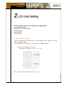
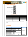
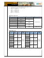
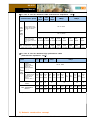
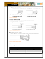
NA-9131
User Manual
Copyright(C) * CREVIS Co.,Ltd * Support +82-31-273-6452 * URL : www.crevis.co.kr
-1-
NA-9131
User Manual
List of Revisions
No.
1
Date
2007.12.15
Version
1.00
Revision
created
Copyright(C) * CREVIS Co.,Ltd * Support +82-31-273-6452 * URL : www.crevis.co.kr
-2-
NA-9131
User Manual
Contents
1. Product Specification
1) General Specifications
2) CC-Link Communication Specification
2. CC-Link Setting
1) Node Address setting
2) Baudrate select switch setting
3) Process image
4) Power setting
5) Specification for CC-Link Ver.1
3. CC-Link Network Installation
1) The maximum length of network for each cable type
2) Network concept
3) CC-Link Cable Specification
4) Connector
5) Minimum radius of bending cable
6) Terminating resistors
7) Connection of shield line with ground
8) Process and connection of CC-Link dedicated cable
4. Check Operation Status
1) L RUN LED
2) L ERR LED
3) RD LED
4) SD LED
5) Field Power LED
Copyright(C) * CREVIS Co.,Ltd * Support +82-31-273-6452 * URL : www.crevis.co.kr
-3-
NA-9131
User Manual
1) General Specifications
Item
Temperature
Humidity
Specifications
Operating
0℃ to +60℃ (32℉ to 140℉)
-20℃ to +60℃ (-4℉ to 140℉)
Storage
-40℃ to +85℃ (-40℉ to 185℉)
Operating
5 to 90% RH (Non-condensing)
Storage
5 to 90% RH (Non-condensing)
Vibration immunity
10 TO 55Hz,double amplitude of 0.75mm,
10minutes on each of 3 axes (X,Y,Z)
Shock Immunity
Peak acceleration and duration
15g/11ms, 3 times on each of 3
axes (X,Y,Z)
Capsuling
Din rail or screw tightening
Remarks
Analog I/O
Discrete I/O
2) CC-Link Communication Specification
Item
Specification
Protocol Version
Version 1
Station Type
Remote Device Station
Number of Nodes
42 Node/Max
Communication speed
156, 625, 2500, 5000, 10000 kbps
I/O Data Size
System area : 16point
RX/RY : 112point (4station occupied)
RWr/RWw : 16channel (4station occupied)
Remarks
Rotary switch
Number of Expansion I/O Max. 32 Slots
Isolation
System power : Non-isolation
System to Logic : Isolation
System Power
Supply voltage : 24Vdc nominal
Voltage range : 11 to 28.8 Vdc
Copyright(C) * CREVIS Co.,Ltd * Support +82-31-273-6452 * URL : www.crevis.co.kr
-4-
NA-9131
User Manual
CC-Link setting include the following configurations:
- Node Address setting
- Baudrate select switch setting
- Process image
- Power setting
- CC-Link Ver.1
1) Node Address Setting
- NA-9131 Node address is determined by the node address rotary switch on the front
panel of adapter module.
- Set node address is recognized on the power-on of adapter module.
Ex) When node address is set as 27:
Device MAC ID Setting :( 2*10 + 1*7 )= 27
Figure 2.1 Rotary switch
* Every CC-Link Adaptor has MAC ID from 0 to 63
Copyright(C) * CREVIS Co.,Ltd * Support +82-31-273-6452 * URL : www.crevis.co.kr
-5-
NA-9131
User Manual
2) Baudrate Select Switch Setting
Figure 2.2 Baudrate select switch
Baudrate
Fixed Addressing
Auto Addressing
156Kbps
0
5
625Kbps
1
6
2.5Mbps
2
7
5Mbps
3
8
10Mbps
4
9
- Fixed Addressing : station 4 occupied
- Auto Addressing : auto setting from station 1 to station4 depending on expansion
I/O Size
3) Process Image
◆ Remote input area
Address
Setting
Size
RXm0~RXmF
station 1
2Byte
RX(m+1)0~RX(m+1)F
station 2
RX(m+2)0~RX(m+2)F
station 2
RX(m+3)0~RX(m+3)F
station 3
RX(m+4)0~RX(m+4)F
station 3
RX(m+5)0~RX(m+5)F
station 4
RX(m+6)0~RX(m+6)F
station 4
RX(m+n)0~RX(m+n)F
n=1,3,5,7
(station1,2,3,4)
Signal name
6Byte
Discrete input
10Byte
14Byte
2Byte
System Area
Copyright(C) * CREVIS Co.,Ltd * Support +82-31-273-6452 * URL : www.crevis.co.kr
-6-
NA-9131
User Manual
m : Register number that was introduled by head station number
n : Final register number for occupied number
station 1 : 16Point(n=1)
station 2 : 48Point(n=3)
station 3 : 80Point(n=5)
station 4 : 112Point(n=7)
◆ Remote output area
Address
Setting
Size
Signal name
RYm0~RYmF
Station 1
2Byte
RY(m+1)0~RY(m+1)F
Station 2
RY(m+2)0~RY(m+2)F
Station 2
RY(m+3)0~RY(m+3)F
Station 3
RY(m+4)0~RY(m+4)F
Station 3
RY(m+5)0~RY(m+5)F
Station 4
RY(m+6)0~RY(m+6)F
Station 4
RY(m+n)0~RY(m+n)F
n=1,3,5,7
(Station1,2,3,4)
6Byte
10Byte
Discrete input
14Byte
2Byte
System Area
◆ RWr/RWw Area
Address
Setting
Size
Signal
name
RWrm0
…
Address
Station 1
4Word
…
RWwm3
RWrm4
RWrm4
Station 2
8Word
RWrm7
…
Analog
Input
RWrm8
…
4Word
Station 2
8Word
Signal
name
Station 3
12Word
…
RWrm12
RWwm12
Station 4
16Word
Analog
Output
RWwm8
RWwm11
RWrm15
Station 1
RWwm7
RWrm11
…
Size
RWwm0
RWrm3
…
setting
…
Station 3
12Word
Station 4
16Word
RWwm15
Copyright(C) * CREVIS Co.,Ltd * Support +82-31-273-6452 * URL : www.crevis.co.kr
-7-
NA-9131
User Manual
4) Power Setting
Figure 2.3 Power setting
System, Field Power
Supply Voltage
24Vdc nominal
Voltage Range
11~28.8Vdc
5) CC-Link Ver.1 Specification
Items
Specification
Max.No of Link Point
Remote In/Output (RX,RY) : 2048 points /each
Remote Resister (RWw) : 256 words
Remote Resister (RWr) : 256 words
Link Point per
Station
Remote In/Output(RX,RY) : 32 points /each
Remote Resister (RWw) : 4 words
Remote Resister (RWr) : 4 words
Link
Point no.
of each
occupied
station
station 1
Remote In/Output(RX,RY) : 32 points /each
Remote Resister (RWw) : 4 words
Remote Resister (RWr) : 4 words
station 2
Remote In/Output(RX,RY) : 64points /each
Remote Resister (RWw) : 8 words
Remote Resister (RWr) : 8 words
station 3
Remote In/Output(RX,RY) : 96 points /each
Remote Resister (RWw) : 12 words
Remote Resister (RWr) : 12 words
Copyright(C) * CREVIS Co.,Ltd * Support +82-31-273-6452 * URL : www.crevis.co.kr
-8-
NA-9131
User Manual
station 4
No. of
Connected
Modules
Remote In/Output (RX,RY) : 128 points/each
Remote Resister (RWw) : 16 words
Remote Resister (RWr) : 16 words
Total Station number
(1×a)+(2×b)+(3×c)+(4×d)≤64
a: Module no.occupied in station 1, b: Module no.occupied in station 2
c: Module no.occupied in station 3, d: Module no.occupied in station 4
Connected module no.
(16×A)+(54×B)+(88×C)≤2304
A: Remote I/O station No. ………………………………… Max.64
B: Remote Device Station no. …………………………… Max.42
C: Local Station,Waiting Master Station, Intelligent Device Station… Max. 26
Copyright(C) * CREVIS Co.,Ltd * Support +82-31-273-6452 * URL : www.crevis.co.kr
-9-
NA-9131
User Manual
CC-Link Network Set up is like following figure
Figure 3.1 in case of system configured with only Remote I/O station and/or Remote device station
Figure 3.2 in case of system including Local and/or intelligent device
1) The maximum length of network for each cable type is as follows
Copyright(C) * CREVIS Co.,Ltd * Support +82-31-273-6452 * URL : www.crevis.co.kr
- 10 -
NA-9131
User Manual
◆ In case of CC-Link dedicated cable (Characteristic Impedance : 100Ω)
156
Kbps
Communication Speed
Stati
on-to
-Stati
on
cable
lengt
h
625
Kbps
2.5
Mbps
5Mbps
10Mbps
1m or more
Between Master/Local,
Intelligent device station
and adjacent stations
※2,※3
2m or more
Between Remote I/O,
Remote device and
Remote I/O, Remote
device stations (shortest
cable) ※1
30cm
30cm
30cm
60cm
or more or more or more or more
Max. transmission distance
1200m
600m
200m
150m
30~
59cm
1m
or more
60~
99cm
30~
59cm
110m
100m
80m
50m
* : Upper line includes only Remote I/O, Remote device station. Lower line includes Local, Intelligent device station.
◆ In case of CC-Link dedicated high performance cable
(Characteristic Impedance: 130Ω)
Communication
speed
Station
to
Station
cable
length
156
625
2.5
Kbps
Kbps
Mbps
5Mbps
between
Master/Local,
Intelligent device
station and
adjacent stations
※2,※3
Between Remote
I/O, Remote device
and Remote I/O,
Remote device
stations
(shortest cable)※1
Max.No. of remote
stations
Max. transmission
distance
10Mbps
1M or more
2M or more
30cm
30cm
30cm
60cm
30cm
1.0M
70cm
64
64
64
1200
900m
400m
-
160m
-
100m
30m
20m
100m
80m
100m
1200
600m
200m
150m
110m
80m
50m
-
-
-
-
-
40~
or
or
or
or
or
or
or
69cm
more more more more more more more
64
30~
39cm
40cm
30cm
30~
or
or
39cm
more
more
64
48
32
* : Upper line includes only Remote I/O, Remote device station. Lower line includes Local, Intelligent device station.
2) Network construction concept
Copyright(C) * CREVIS Co.,Ltd * Support +82-31-273-6452 * URL : www.crevis.co.kr
- 11 -
NA-9131
User Manual
There are Master and Slave for Node. The master controls CC-Link
and arranges external I/O. The Slave connect to external I/O. You
can arrange Master and Slave in any position of Node as the above
picture.
Node
a Trunk line means the cable attached terminal resistor on both
edges. a Branch line means the cable branched off from trunk line.
(Branch length : Max. 6M)
Trunk Line/
Branch Line
The resisters are attached at both edges of cable. The resister
reduces reflected wave at terminal point and prevents disturbance of
Terminal Resistor signal. Use resisters suitable for cable used.
CC-Link dedicated cable 110Ω±5% 1/2W
CC-Link dedicated high flexible cable 130Ω±5% 1/2W
Connection Type
CC-Link basic connection is multi drop connection. And T-branch
connection is available in case of 625Kbps or less of communication
speed or in case of using repeater .
3) CC-Link Cable Specification
CC-Link dedicated cable shall be used in CC-Link system.
Specification of CC-Link dedicated cable is as follow
Figure 3.3 CC-Link Cable
◆ The color of isolator and terminal connector
Color of isolator
Terminal
Blue
DA
White
DB
Yellow
DG
Grounding wire(Shield)
SLD
◆ Specification of CC-Link dedicated cable
Copyright(C) * CREVIS Co.,Ltd * Support +82-31-273-6452 * URL : www.crevis.co.kr
- 12 -
NA-9131
User Manual
Item
Specifications
Cable Type
Shield twisted cable
Finish outer diameter
8.0mm or less
Drain line
20 lines/0.18 mm or 24 lines/0.18mm
Insert separately or in a bundle between the
ground cable bundle and aluminum tape.
Conductor resistance(20℃)
37.8Ω/km
Insulation resistance
10000MΩㆍkm or more
Withstand voltage
500VDC 1minute
Electrostatic capacity(1kHz)
60nF/km or less
Characteristic impedance
Attenuation amount
1MHz
110±15Ω
5MHz
110±6Ω
1MHz
1.6dB/100mor less
5MHz
3.5dB/100mor less
4) Connector
Recommended specifications of connector relaying between CC-Link dedicated cables are
as followings
◆ M12(Micro) type(4cores)
M12(Micro)type
Pin position
Resistance of
conductor
5m ohm or less
Thickness of
Gold plate
0.1 micro m or more
Type of water proof
IP67(JIS C 0920)
Pin position
1pin
2pin
3pin
4pin
:
:
:
:
SLD
DB
DG
DA
◆ Easy connection water proof type (4cores)
Easy connection water proof type
Contact resistance
5m ohm or less
Thickness of gold plate
0.5 micro m or more
Type of Water proof
IP67 (JIS C 0920)
Conducts
Pin position
Copyright(C) * CREVIS Co.,Ltd * Support +82-31-273-6452 * URL : www.crevis.co.kr
- 13 -
NA-9131
User Manual
4 conductors
1pin
2pin
3pin
4pin
:
:
:
:
SLD
DB
DG
DA
5) Minimum radius of bending cable
Please keep the minimum radius of bending in using CC-Link dedicated cable.
When it is used with less than min. radius by constraint, it may cause pulling out from
connector and cable, breaking of cable, etc..
Minimum radius of
Bending cable
Connecting
Major diameter of cable× 10 or more
Stable
Major diameter of cable× 4 or more
connecting : Minimum radius of bending cable permitted in only connecting
stable : Minimum radius of bending cable at stable permits the characteristic for long period.
6) Terminator Resistors
Specification of terminator Resistors are as follows Resistance Spec. :
- CC-Link dedicated cable 110Ω±5% 1/2W
- CC-Link dedicate high performance cable 130Ω±5% 1/2W
Figure 3.4
Connection of terminal resister
◆ T-Branch connection
- When repeater is not used
Please connect terminal resister, 110Ω±5% 1/2W between DA and DB on each
edge of trunk line. (Do Not use CC-Link dedicated high performance cable)
- When repeater is used
Please use Terminal resistor included in Repeater unit.
Copyright(C) * CREVIS Co.,Ltd * Support +82-31-273-6452 * URL : www.crevis.co.kr
- 14 -
NA-9131
User Manual
7) Connection of shield line with ground
- Connect both edges of shield wire for CC-Link dedicated cable with "SLD" of each module.
- Connect "FG" of each module independently.
- Always ground the FG terminal to the protective ground conductor
(Ground resistance 100Ω or less)
- If not use ground independently, use common ground according to the Figure 3.5
Figure 3.5 Shield line with ground
8) Process and connection of CC-Link dedicated cable
Process CC-Link dedicated cable according to the table, As well, refer to the table for the
length of removed cable coat, the length of removed signal wire coat and terminal process
of signal wire.
The length of removed The length of removed
cable coat
signal wire coat
50mm
3mm
Terminal process of
signal wire
Pressure terminal
◆ Removing cable coat
Remove CC-Link dedicated cable coat not to scratch shield mesh. But not remove extra
amounts not to cause short.
Figure 3.6 Removed cable coat
◆ Process shield
Ravel shield mesh carefully. As well as signal wire, there is one bare drain wire
(stranded wire or each wire). Process the shield according to any of followings.
(1) When shield mesh is used
Coat with isolation tube after putting tightly shield mesh and drain wire together.
Copyright(C) * CREVIS Co.,Ltd * Support +82-31-273-6452 * URL : www.crevis.co.kr
- 15 -
NA-9131
User Manual
(2) When drain wire is used
Coat drain wire with isolation tube after trimming off the a excess shield mesh.
Figure 3.7 Process shield
◆ Remove signal wire coat
Remove coat of signal wire according to size of Pressure terminal.
Put tightly bear signal wire together.
Figure 3.7 Remove signal wire coat
◆ Connection pressure terminal
Connect signal wire removed coat, shield wire with pressure terminal differently.
Figure 3.8 Connection pressure terminal
◆ Connection terminal
Connect signal wire attached pressure terminal with each terminal then drive a screw in
tightly. Refer to the table as to name of terminal and color of cable conductor
Terminal
Signal conductor
DA
Blue
DB
White
DG
Yellow
SLD
Ground(Shield)
Copyright(C) * CREVIS Co.,Ltd * Support +82-31-273-6452 * URL : www.crevis.co.kr
- 16 -
NA-9131
User Manual
When all installation and configuration processes are complete, the adaptor module Indicator
LED and Field Power LED shall be lit in a green color. If not, it indicates that an error has
occurred. See the following table for proper measures.
Status Indicator LED
1) L RUN LED
Status
State
To indicate
Device is not on-line or may be not powered
Not Powered Not On-Line Off
Resetting Hardware
Connection-Timeout
Off
Device is Timeout
On-Line, Connection
Green On
Device is on-line and allocated to a master
2) L ERR LED
Status
State
To indicate
Fail
On
CRC error
Switch Setting error
On
Invalid MAC ID
Communication error
On
Baudrate switch setting error
Setting change
Flashing
Switch setting has been changed from the setting at
the reset cancelation
Device Operational
Off
The unit is operating in normal condition
3) RD LED
Status
State
To indicate
Connection
On
Detecting the carrier for channel 1 or 2
Unable detect
Off
Unable to detect carriers neither for channel 1 or 2
Copyright(C) * CREVIS Co.,Ltd * Support +82-31-273-6452 * URL : www.crevis.co.kr
- 17 -
NA-9131
User Manual
4) SD LED
Status
State
To indicate
Connection
On
During transmission
Not transmission
Off
Other than listed in the left
5) Field Power LED
Status
State
To indicate
Not supplied Field Power
Off
Not supplied 24Vdc field power
Supplied Field Power
Green
Supplied 24Vdc field power
Copyright(C) * CREVIS Co.,Ltd * Support +82-31-273-6452 * URL : www.crevis.co.kr
- 18 -