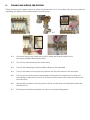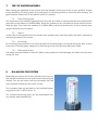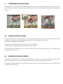
1
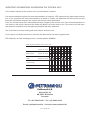
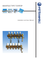
MANIFOLD TYPE 7035TOP
Installation and User Manual
INDEX
1.
2.
3.
4.
5.
6.
7.
8.
9.
10.
11.
CONTENTS
INSTALLATION STANDARDS
PLACING THE PIPES
CONNECTING THE PIPES
CONNECTING THE MIXING UNIT
FILLING AND AIRING THE SYSTEM
TEST OF WATERTIGHTNESS
BALANCING THE SYSTEM
CONNECTING THE ACTUATORS
WIRED CONTROL SYSTEM
WIRELESS CONTROL SYSTEM
1.
CONTENTS
The Pettinaroli manifolds are made of extruded copper, type
OT58.
The Pettinaroli manifold system is delivered with 2 to 12 outlets,
and the manifold is mounted on wall brackets. The upper manifold for the inlet water is supplied with topmeters for balancing the circuits. The manifold below is for the outlet water. This
manifold is supplied with thermostatic valves / hand wheels for
regulation. The manifold is delivered with two pre-assembled
terminal sets (T-piece, drain/filling ball valve and air vent).
2. INSTALLATION STANDARDS
The heating system has to content and to be regulated according to the current standards, which you find
in the regulations for buildings. And according to the standards for heating systems.
The basics are the heat loss in the house, the way you place the pipes in the floor and the choosen construction of the floor. The floor heating pipe has to be placed in the floor according to the instructions for
the choosen construction.
3.
PLACING THE PIPES
To achieve the most optimal comfort in the room, the pipes have to be placed in the floor after the standard principles. If there have been made drawings of the installation, the
pipes have to be placed according to those drawings.
To achieve the best result – planning how to place the pipes in the floor
is very important.
Before placing the pipe in the floor you have to connect the pipe to the
inlet manifold. When the pipe has been placed in the floor, the end of
the pipe will be connected to the outlet manifold. Placing the pipe has
been completed.
4.
CONNECTING THE PIPES
Lead the pipe to the upper bar. Cut of the pipe at the right length. It is important with a sharp and straight
cut. Place the fitting at the pipe and connect it to the manifold.
5.
CONNECTING THE MIXING UNIT
To achieve the most optimal comfort in the room and the best solution saving money at energy costs, it is
very important that the system will be supplied with water at the right temperature.
The correct temperature can be calculated in the programme which you will be able to find at our web-site
www.pettinaroli.dk. If the heating source can not ensure the correct temperature, it will be necessary to
connect a mixing unit to the system.
7021
7021
REMEMBER
GASKET
Alpha+ Pump
Floor heating systems: Turn the
pump into the position showen
above.
The mixing unit 7021 with Grundfos Alpha2 pump, has to be mounted on the left side of the manifold.
The calculated temperature will be regulated by the thermostat.
It will be possible to mount the mixing unit on the right hand. But it is very important to be aware of this
before connecting the pipes to the manifolds, because the upper bar has to be moved one place to the
left, or else it does not fit with the mixing unit.
If there is no room for the mixing unit in continuation of the manifold, it is possible to mount it with an
angle set art. ACC7016.
6.
FILLING AND AIRING THE SYSTEM
Filling and airing the system has to be done very systematic. Air in the system can give you problems
regulating the system and in worst case burn of the pump.
6.1
6.2
6.4
6.3
6.5
6.1.
Connect a hose to the upper bar and fill in water and lead air/water out of the return manifold with another hose.
6.2.
Turn off the thermostat and the return valve
6.3.
Turn off the balancing and thermostatic valves on the manifolds
6.4.
Turn on the water on the upper bar and open for the drain valve on the bar below
6.5.
Turn on the circuit (top meter/thermostatic valves) which is closed to the mixing unit. Keep filling in water until no more air comes out of the drain valve. Now you can turn off the first circuit.
6.6.
Repeat this procedure circuit by circuit, until all circuits have been filled with water and drained for air.
Dismount the hoses and replace the caps on the drain/filling valves
6.7.
7.
TEST OF WATERTIGHTNESS
When testing the tightness all top meters and thermostatic valves have to be in open position. If there
is any possibility of freezing water, then add glycol or something similar to avoid the pipes busting. The
glycol shall be washed out of the system before it is started.
7.1. Floor heating pipes
The pipes have to be tested for tightness when they still are visible. If nothing else has been specified the
pipes have to be tested by 0,6MPa (6Bar). Keep the pressure for 30 minutes and check that all connections are tight. Then lower the pressure to 0,3MPa (3Bar). Keep this pressure for 2 hours, without dropping the pressure on the system.
7.2. Report
A report has to be prepared form the results of the pressure test. Keep this report with other manuals for
the heating system of the house.
7.3. Concreting
By concreting, the pipes have to be under pressure to avoid damage on the pipes during the work. If there
is any risk of freezing pipes, add glycol or something similar until the work has been ended.
7.4. Other types of floor
It is always recommendable to keep the pipes under pressure to avoid damage and leaks from the pipes
during the work.
8.
BALANCING THE SYSTEM
Balancing the system will be done directly at the top meters. All the circuits have to be closed, when balancing the
circuits. Turn the top meter until the necessary flow has
been reached. Repeat this for all the circuits.
The necessary flow can be found in the manifold balancing guide for the 7035TOP (Encl. 1).
The manifold balancing guide can be downloaded from
our website www.pettinaroli.dk.
9.
CONNECTING THE ACTUATORS
According to the standards DS469, a heating system which is the primary heating souce has to be regulated automaticly. Below it is illustrated how to replace the hand wheels with actuators for controlling the
system.
10. WIRED CONTROL SYSTEM
The system consits of a control system for 1 to 12 heating zones which is controlled by room thermostats
and max. 14 actuators, which regulate the quantity of water supplying the circuits.
Pettinaroli has 230V and 24V systems.
Components for 230V systems have the series number 2000
Components for 24V systems have the series number 4000
The quick guide for installation of the wired control system can be downloaded from our website www.
pettinaroli.dk, see Encl.: 2
11. WIRELESS CONTROL SYSTEM
The system consits of a 6 or 12 canal control system to control 1 to 12 heating zones with a 868 MHz
signal and max 13 actuators, which regulate the quantity of water supplying the circuits.
The quick guide for installation of the wireless control system can be downloaded from our website www.
pettinaroli.dk, see Encl.: 3
MANIFOLD BALANCING GUIDE - 7035TOP
GUIDED INSTALLATION OF PETTINAROLI FLOORHEATING SET
The balancing is done with all circuits closed at the start and by turning
the top meter until the correct flow is read.
The needed flow can be found in the table below:
Area per circuit
m²
Pipe length
m
Flow needed
l/min
2
4
6
8
10
12
14
16
18
20
22
25
28
32
36
7
13
20
27
33
40
47
53
60
67
73
83
93
107
120
0,3
0,6
0,9
1,1
1,4
1,7
2,0
2,3
2,6
2,9
3,1
3,6
4,0
4,6
5,1
The needed flow is calculated based on a heatloss of 50 W/m² and a temperature difference
(delta T) of 5°C.
In newer buildings without large window areas the necessary flow may be reduced
by up to 30%.
The shown pipe lengths are the part residing in the heated room (excl. pipe from the manifold
to the room) placed with a centre distance of 30 cm.
By using 20mm PEX-pipe the max. Recommended pipe length is 120 m.
If other pipe types/dismeters are used, please see our Underfloor Heating Software
(PFLOOR2) for max. pipe lengths. The program can be found at www.pettinaroli.dk
Pettinaroli Hotline : +45 6341 6666
Encl. 1
INSTALLATION OF
THE CONTROL UNIT
CONNECTION OF
TRANSFORMER
Correct wire´s installation.
CABLE FROM THE
ROOMTERMOSTAT
Lead the wires through the systembox.
Put away 10 mm of the isolating
material from the cable.
Place the cable in the lowest part of
the control unit
Put the wires in the respective slots
CONNECTION OF
INSTALLATION
Connect the transformer with the
control unit
If the cables have to be behind the
control unit, use the four spacers
Make sure the screws are in the
right position before proceeding
Place the connecting part over the
control unit.
Lock the connection by turning the
screws 1/4 around
CONNECTION OF
THE THERMOSTAT
Install the control unit on the wall
with the included screws
Connect the cables from the
roomthermostat with the upper row
Place the cables according to the
colours, pressing them well
Connect the cables from the transformer in the same way
Correctly connected cables
CONNECTION OF
THE ACTUATORS
In the same way remove the connecting part
Connect the cables from the actuator with the lower row
Press the cables into the slots of the
lower edge of the connection part
Press the cables well, observing the
matching colours
Only 4 actuators can be connected
in the same zone. Max 14 per box
READY FOR WORKING
QUICK GUIDE FOR INSTALLTION OF WIRED FLOORHEATING
Turn the screw 1/4 and remove the
cover
Place the cover on the box, make
sure the screws are locked correctly.
Connect the box to the electrical
power
Power diode lightens up when the
power is connected.
The diode of each zone lightens
when the actuator opens.
Yellow/green
Blue
Brown
Black
Black
Between brown and
yellow/green wire
Between blue and
yellow/green wire
Encl. 2
INSTALLATION OF
THE SYSTEMBOX
OPEN THE COVER
OF THE BOX
Turn the screws to lift the cover
Control the screws are in correct
position before placing the cover
Press the wires from the actuators
into the slots on the box´ underside.
Press well the cables into the slots,
according to the colour.
The controlbox can be dismounted
by loosening the clips under it
If the cable has to be removed again
you can loosen it with a screwdriver
INSTALLATION OF
THE THERMOSTAT
Write the name on it and place the
batteries in the rear slot
Mount the base and push the
thermostat in place. Put on the cap
CONNECTION OF
THE SYSTEMBOX
TIP!
Connect the box to the electrical
power
Power diode starts lighting up
The actuators start an automatical
setting (takes 15 min.)
During this procedure the diodes will
turn on and off for all the zones
PROGRAMMING
THEMOSTAT
CONNECTION OF
THE ACTUATOR
1) Hang the box on the rail
2) Place the controlbox in place
Under the cover there´s a set-button
and a label to give it a name.
Press down the set-button for 5
seconds
Diode 1 blinks. Press shortly the setbutton to change to zone 2-3...
Press the set-button of the thermostat within 3 minutes
Diode of the zone will stop blinking
RESETTING OF THE
PROGRAMMING
GUIDE TO INSTALLATION OF WIRELESS FLOORHEATING
Mount the rail on the wall with the
included screws
When writing room description and
zone of each thermostat you can
take this out of the systembox.
When the programming is over the
thermostats can be mounted again
on the bases.
Press down the set-button for 5 sec. Diode for zone 1 will now start blinking.
Press down the set-button again (this time for 10 sec.), all diodes will blink.
The system is now reset and diode 1 will blink.
Encl. 3
PETTINAROLI WIRELESS SYSTEM
4 COMMON QUESTIONS:
1. One or more diodes blinks on the control system after programming the room thermo-
stats.
There is no contact between the room thermostat and the control unit.
A) The problem can be the following:
To check that the room thermostat is programmed to the right zone, keep the set-button down for 10 seconds. Is the room thermostat programmed correctly, the following will happen:
The diode on the control unit will turn on the red light (it is calling for heat), then the actuators will open and close within 15 minutes.
B) Check that the batteries are placed correctly in the roomthermostat.
C) D) Pull out the plug to the control unit and insert again. A self-test will now be running. All diodes which are programmed to a roomthermostat will now blink, constantly lighten up and then turn off, if they do not call for heat.
The actuators will open and close, and heat will be sent out in the circuits. This procedure will last approx. 25 minutes.
If one or more of the diodes blinks after this self-test, it is recommendable to re-programme the room thermostats, please look in the guide.
The room thermostat can not reach the control unit. Normally the operational range is 25 me-
ters, but some constructive conditions in the building can give some problems. For instance electronical components and boxes in metal placed close to the control unit. An external anten
na can solve this problem
During programming of the room thermostat, do not touch the print-plate on the back of the roomthermostat. It is also recommendable to keep the room thermostat at least 1 meter from the control unit during
the programming.
2. How often do you have to change batteries?
The nomal lifetime of the batteries are 3 years. Do not use rechargeable batteries.
OBS: Be careful when you place/replace the batteries.
3. How can you know that you have to change the batteries?
If a diode starts blinking, there is no contact between the roomthermostat and the control unit. Is it not possible to activate the room thermostat by pressing down the set-button for 10 seconds (the diode on the circuit will lighten up) it might be the batteries which have to be changed.
4. How much power does the system use per year?
Each actuator use 3 Watt during start-up and 2 Watt during operation.
Per actuator : 1750 hours/year à 2 Watt
= 3,5 kWh/year
Notes
__________________________________________________________________________
__________________________________________________________________________
__________________________________________________________________________
__________________________________________________________________________
__________________________________________________________________________
__________________________________________________________________________
__________________________________________________________________________
__________________________________________________________________________
__________________________________________________________________________
__________________________________________________________________________
__________________________________________________________________________
__________________________________________________________________________
__________________________________________________________________________
__________________________________________________________________________
__________________________________________________________________________
__________________________________________________________________________
__________________________________________________________________________
__________________________________________________________________________
__________________________________________________________________________
__________________________________________________________________________
__________________________________________________________________________
__________________________________________________________________________
__________________________________________________________________________
__________________________________________________________________________
__________________________________________________________________________
__________________________________________________________________________
__________________________________________________________________________
__________________________________________________________________________
__________________________________________________________________________
__________________________________________________________________________
__________________________________________________________________________
__________________________________________________________________________
__________________________________________________________________________
__________________________________________________________________________
__________________________________________________________________________
__________________________________________________________________________
__________________________________________________________________________
__________________________________________________________________________
__________________________________________________________________________
__________________________________________________________________________
__________________________________________________________________________
__________________________________________________________________________
__________________________________________________________________________
__________________________________________________________________________
__________________________________________________________________________
�
�CONCERNING THE CONTROL UNIT:
IMPORTANT INFORMATIONS
In the plastic cabinet at the control
� unit a circuit breaker is placed.
It is recommendable to place the room thermostats in a height of 1.50 meter and in a place without direct
sun. If you just place the room�
thermostat on a closet or a table, the batteries will fall out and you will
loose the connection between the control unit and the room thermostat.
Every 10 minutes each room thermostat will send a signal to the control unit. If the room temperature is
�
not correct it will call for heat and the diode will lighten up in the control unit. The control unit will open
and close the actuators until the right temperature has been achieved.
��
The time before the floor heating will react can be several hours.
��it will keep the data which has been programmed.
If the control unit loose the power
LED frequency of each heating zone for a control system 868MHz:
��
��������������������������������������
Blink frequency of diode on the control unit.
Normal operation
�����������
Output active
������������
��������������
Output not active
AR 4070
�������
���������������
Battery weak
Output active
������������
��������������
Output not active
receiver signal
��������������
�����week
Output active
������������
��������������
Output not active
Independent of the status
�������������������
of each output
��������������
Emergency operation
��������
Programm mode
�������������
�
���
�
�
�
�
������
�
�
������
�����������������������������������
�����������
�������������
���������������
�������
�����������
�������������
���������������
��������������
�������������
���������������
����������������������Pettinaroli A/S
Mandal Allé 21
��������������
�������������������
DK-5500 Middelfart
Denmark
����������������
�
Tel: +45 6341 6666 • Fax: �+45��� 6341
6660�
E-mail: [email protected] • Internet: www.pettinaroli.dk
Composite
Rev. 1.5 - Oktober 2010