1
Process Supervisor
T940X
Handbook
E U ROT H E R M
E U ROT H E R M
Declaration of Conformity
Manufacturer's name:
Eurotherm Limited
Manufacturer's address:
Faraday Close, Worthing, West Sussex,
BN13 3PL, United Kingdom
Product type:
Process Supervisor
Models:
T940X Processor module (Status level A1 or higher)
T320 Connection Module (Status level T12 or higher)
T310 Backplane
(Status level T11 or higher)
Safety specification:
BS EN61010-1: 2001-02
EMC emissions specification: BS EN61326 2002-02
EMC immunity specification: BS EN61326 2002-02
Eurotherm Limited hereby declares that the above products conform to the safety and EMC
specifications listed. Eurotherm Limited further declares that the above products comply
with the EMC Directive 89 / 336 / EEC amended by 93 / 68 / EEC, and also with the Low
Voltage Directive 73 / 23 / EEC.
Signed:
Dated:
Signed for and on behalf of Eurotherm Limited
William Davis
(General Manager)
IA249986U610 Issue 2 Aug 04
© 2004 Eurotherm Limited
All rights are strictly reserved. No part of this document may be reproduced, modified, or transmitted in any form by
any means, nor may it be stored in a retrieval system other than for the purpose to act as an aid in operating the
equipment to which the document relates, without the prior written permission of Eurotherm limited.
Eurotherm Limited pursues a policy of continuous development and product improvement. The specifications in this
document may therefore be changed without notice. The information in this document is given in good faith, but is
intended for guidance only. Eurotherm Limited will accept no responsibility for any losses arising from errors in this
document.
PROCESSS SUPERVISOR HANDBOOK
PROCESS SUPERVISOR HANDBOOK
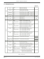
LIST OF CHAPTERS
Section
Title
Issue level
Contents
....................................................................... 3
Chapter 1
Introduction ...................................................... 2
Chapter 2
Installation ........................................................ 2
Chapter 3
User interface ................................................... 2
Chapter 4
Start-up ............................................................ 2
Chapter 5
Configuration ................................................... 3
Chapter 6
Error conditions and diagnostics ......................... 2
Chapter 7
Task Scheduling and Tuning................................ 2
Chapter 8
Service ............................................................ 2
Chapter 9
Index
Specification and order codes ............................ 3
....................................................................... 3
EFFECTIVITY
This manual refers to Process Supervisor units fitted with Version V4/1 software.
See The Modbus/Profibus manual for details of serial communications.
HA028225
Issue 3 Jly 04
Section i
Page i - 1
PROCESS SUPERVISOR HANDBOOK
LIST OF CONTENTS
Section
Page
GLOSSARY OF TERMS ......................................................................... I - 9
CHAPTER 1 INTRODUCTION .............................................................. 1 - 1
1.1 MANUAL CONTENTS ............................................................................... 1 - 1
1.2 OTHER INFORMATION SOURCES ............................................................. 1 - 1
1.3 THE PROCESS SUPERVISOR UNITS ............................................................ 1 - 1
1.3.1 Typical applications .......................................................................... 1 - 2
1.3.2 Features ........................................................................................... 1 - 2
LIN .................................................................................................. 1 - 2
MODBUS ......................................................................................... 1 - 2
PROFIBUS. ....................................................................................... 1 - 2
REDUNDANT PROCESSOR MODULES ............................................... 1 - 2
AUTOMATIC TAKE-OVER ................................................................... 1 - 2
REDUNDANT POWER SUPPLY CONNECTION ................................... 1 - 2
LIVE PROCESSOR REPLACEMENT ...................................................... 1 - 2
DIAGNOSTICS ................................................................................. 1 - 2
FRONT PANEL ANNUNCIATION. ...................................................... 1 - 2
CONTINUOUS HEALTH MONITORING .............................................. 1 - 2
WATCHDOG ................................................................................... 1 - 3
I/O ................................................................................................. 1 - 3
CONFIGURATION. ........................................................................... 1 - 3
BLOCK STRUCTURE. ......................................................................... 1 - 3
ST USER ALGORITHMS ..................................................................... 1 - 3
BLOCK SUPPORT .............................................................................. 1 - 3
ENCLOSURES .................................................................................. 1 - 3
CHAPTER 2 INSTALLATION ................................................................ 2 - 1
2.1 SAFETY AND EMC INFORMATION ............................................................ 2 - 1
2.1.1 Installation requirements for EMC ....................................................... 2 - 1
2.1.2 Installation safety requirements ........................................................... 2 - 2
PERSONNEL .................................................................................... 2 - 2
HAZARDOUS VOLTAGES .................................................................. 2 - 2
CONDUCTIVE POLLUTION ................................................................ 2 - 2
VENTILATION ................................................................................... 2 - 2
PRECAUTIONS AGAINST ELECTROSTATIC DISCHARGE ...................... 2 - 2
2.1.3 Keeping the product safe ................................................................... 2 - 2
MISUSE OF EQUIPMENT ................................................................... 2 - 2
SERVICE AND REPAIRS ..................................................................... 2 - 2
2.2 UNPACKING ............................................................................................ 2 - 2
2.2.1 Handling precautions ........................................................................ 2 - 3
2.2.2 Package contents .............................................................................. 2 - 3
PRODUCT LABELLING ....................................................................... 2 - 3
2.3 MECHANICAL LAYOUT AND INSTALLATION .............................................. 2 - 3
2.3.1 Layout drawings ............................................................................... 2 - 4
2.3.2 Removal of modules .......................................................................... 2 - 5
2.3.3 Fitting of modules ............................................................................. 2 - 5
2.4 BACKPLANE SWITCHES ............................................................................ 2 - 5
2.4.1 Location ........................................................................................... 2 - 5
2.4.2 Switch functions ................................................................................ 2 - 6
SW1: LIN ADDRESS SETTING SWITCH .............................................. 2 - 6
SW2: OPTIONS SWITCH .................................................................. 2 - 7
WDR (WATCHDOG RETRY) ............................................................... 2 - 7
MDB (MODBUS ENABLE) .................................................................. 2 - 7
SRD (REDUNDANCY DISABLE) ........................................................... 2 - 7
Cont...
Section i
Page i - 2
HA028225
Issue 3 Jly 04
PROCESSS SUPERVISOR HANDBOOK
LIST OF CONTENTS (Cont.)
Section
Page
2.5 CONNECTIONS AND WIRING ................................................................. 2 - 8
2.5.1 Connect module ................................................................................ 2 - 9
COMMUNICATIONS CONNECTORS .............................................. 2 - 10
ELIN CONNECTORS ...................................................................... 2 - 11
ALIN CONNECTORS ...................................................................... 2 - 12
ELIN HUBS ..................................................................................... 2 - 13
ALIN HUBS (ACTIVE) ....................................................................... 2 - 13
ALIN HUBS (PASSIVE) ..................................................................... 2 - 14
DAISY-CHAIN LAYOUT .................................................................... 2 - 14
CABLING ....................................................................................... 2 - 14
DC SUPPLY WIRING ....................................................................... 2 - 15
RELAY WIRING ............................................................................... 2 - 16
2.5.2 Processor module ............................................................................ 2 - 17
CONFIGURATION OF CONTROL STRATEGIES AND SEQUENCES ..... 2 - 19
TERMINAL CONFIGURATOR RESTRICTIONS ..................................... 2 - 19
2.5.3 Safety earth connection ................................................................... 2 - 19
2.5.4 Transparent Modbus Access (TMA) ................................................... 2 - 20
CHAPTER 3 USER INTERFACE ............................................................. 3 - 1
3.1 INTRODUCTION ....................................................................................... 3 - 1
3.2 POWER MONITORING LEDS ...................................................................... 3 - 3
3.2.1 A and B ........................................................................................... 3 - 3
3.2.2 ext ................................................................................................... 3 - 3
3.2.3 int ................................................................................................... 3 - 3
3.3 ALARM LEDS ............................................................................................. 3 - 4
3.4 COMMS LEDS .......................................................................................... 3 - 5
3.4.1 System A/B, i/oA, i/oB .................................................................... 3 - 5
3.4.2 Exp1 tx/rx ....................................................................................... 3 - 5
3.4.3 Exp2 tx/rx ....................................................................................... 3 - 5
3.5 CHANGEOVER LEDS AND SWITCHES ........................................................ 3 - 6
3.5.1 Primary LED ...................................................................................... 3 - 6
3.5.2 Standby LED ..................................................................................... 3 - 6
3.5.3 Sync/changeover switch .................................................................... 3 - 6
3.5.4 Desync switch ................................................................................... 3 - 6
3.5.5 Processor module Synchronisation ...................................................... 3 - 7
TIME TO SYNCHRONISE .................................................................. 3 - 7
3.6 STARTUP LEDS AND SWITCHES ................................................................. 3 - 8
3.6.1 wdog LED ........................................................................................ 3 - 8
3.6.2 Duplex LED ........................................................................................ 3 - 8
3.6.3 Restart switch ................................................................................... 3 - 8
3.6.4 Halt switch ........................................................................................ 3 - 9
3.6.5 Start up mode .................................................................................... 3 - 9
HOT ................................................................................................ 3 - 9
COLD .............................................................................................. 3 - 9
HOT/COLD ...................................................................................... 3 - 9
TEST ................................................................................................ 3 - 9
Cont...
HA028225
Issue 3 Jly 04
Section i
Page i - 3
PROCESS SUPERVISOR HANDBOOK
LIST OF CONTENTS
Section
Page
CHAPTER 4 START-UP ........................................................................ 4 - 1
4.1 REDUNDANCY MODES ............................................................................ 4 - 1
4.2 START-UP MODES ..................................................................................... 4 - 1
4.2.1 Hot start ........................................................................................... 4 - 1
TEPID DATA ...................................................................................... 4 - 2
4.2.2 Cold start ......................................................................................... 4 - 2
PARAMETER FILE ............................................................................... 4 - 2
4.2.3 Hot/cold start ................................................................................... 4 - 3
4.2.4 Test start ........................................................................................... 4 - 3
4.3 STARTING A SINGLE (NON REDUNDANT) PROCESSOR .............................. 4 - 5
4.3.1 Start-up sequence .............................................................................. 4 - 5
OFF STATE ....................................................................................... 4 - 5
STARTING STATE .............................................................................. 4 - 5
PRIMARY UNSYNCH STATE ............................................................... 4 - 6
4.3.2 Watchdog indications ....................................................................... 4 - 6
4.3.3 Watchdog relay ................................................................................ 4 - 6
4.4 STARTING UP A PAIR OF PROCESSORS ...................................................... 4 - 7
4.4.1 Redundant mode ............................................................................... 4 - 7
PRIMARY/SECONDARY CRITERIA ...................................................... 4 - 7
AUTOSYNCHRONISATION ............................................................... 4 - 8
SYNCHRONISATION ........................................................................ 4 - 8
TIME TO SYNCHRONISE .................................................................. 4 - 8
4.4.2 Non-redundant mode ........................................................................ 4 - 8
4.5 LED FAULT INDICATIONS ........................................................................... 4 - 9
POWER A/B LEDS ............................................................................ 4 - 9
WATCHDOG LED ............................................................................. 4 - 9
PRIMARY LED ................................................................................... 4 - 9
COMMS LEDS .................................................................................. 4 - 9
SYSTEM AND I/O LEDS. ................................................................... 4 - 9
EXP1, EXP2 LEDS. ............................................................................. 4 - 9
DUPLEX LED .................................................................................... 4 - 10
4.6 START-UP WITH A CONFIG TERMINAL ..................................................... 4 - 10
4.6.1 M Monitor ...................................................................................... 4 - 10
4.7 START-UP WITH SERVER STALL .................................................................. 4 - 11
4.8 REDUNDANT MODE WORKING ............................................................. 4 - 11
4.8.1 Redundancy decisions ..................................................................... 4 - 11
4.8.2 Profibus Examples ........................................................................... 4 - 12
Cont...
Section i
Page i - 4
HA028225
Issue 3 Jly 04
PROCESSS SUPERVISOR HANDBOOK
LIST OF CONTENTS
Section
Page
CHAPTER 5 CONFIGURATION ............................................................ 5 - 1
5.1 TOOLS: THE CONFIGURATOR AND LINTOOLS .......................................... 5 - 1
5.2 CONFIGURABLE ITEMS ............................................................................. 5 - 1
5.2.1 Configuration Access ........................................................................ 5 - 2
5.3 PREPARING TO RUN THE CONFIGURATOR ................................................ 5 - 2
5.3.1 Connecting to a PC. .......................................................................... 5 - 2
5.3.2 Setting the control efficiency ............................................................... 5 - 2
NON-REDUNDANT (SIMPLEX) SYSTEM .............................................. 5 - 2
REDUNDANT (DUPLEX) SYSTEM ........................................................ 5 - 2
5.4 RUNNING THE CONFIGURATOR .............................................................. 5 - 3
5.4.1 Initial menu access ............................................................................ 5 - 3
IP SUBNETS ..................................................................................... 5 - 4
5.4.2 The Initial menu ................................................................................ 5 - 5
5.4.3 Quitting the terminal emulation program ............................................. 5 - 5
5.5 DATABASE CONFIGURATION ................................................................... 5 - 5
5.5.1 MAKE .............................................................................................. 5 - 6
BLOCK OVERVIEW ........................................................................... 5 - 7
CONNECTION TYPES IN A PROCESSOR MODULE DATABASE .......... 5 - 11
5.5.2 COPY ............................................................................................ 5 - 12
5.5.3 DELETE ........................................................................................... 5 - 12
5.5.4 INSPECT ........................................................................................ 5 - 13
5.5.5 NETWORK ..................................................................................... 5 - 13
5.5.6 UTILITIES ........................................................................................ 5 - 14
START, STOP UTILITIES ..................................................................... 5 - 14
SAVE UTILITY .................................................................................. 5 - 14
LOAD UTILITY ................................................................................. 5 - 15
FILE UTILITY .................................................................................... 5 - 15
APPLY/UNDO UTILITIES ................................................................... 5 - 15
ELIN SETUP .................................................................................... 5 - 16
5.5.7 ALARMS ........................................................................................ 5 - 16
5.6 MODBUS CONFIGURATION ................................................................... 5 - 17
5.6.1 MODE ........................................................................................... 5 - 17
5.6.2 SETUP ............................................................................................ 5 - 17
5.6.3 Tables ............................................................................................ 5 - 18
TABLES LIST .................................................................................... 5 - 18
TABLE MENUS ................................................................................ 5 - 19
5.6.4 Utilities ........................................................................................... 5 - 21
Cont...
HA028225
Issue 3 Jly 04
Section i
Page i - 5
PROCESS SUPERVISOR HANDBOOK
LIST OF CONTENTS
Section
Page
CHAPTER 6 ERROR CONDITIONS & DIAGNOSTICS .............................. 6 - 1
6.1 ERROR INDICATION TYPES ....................................................................... 6 - 1
6.2 PROCESSOR MODULE FRONT PANEL ERROR DISPLAYS ............................... 6 - 2
6.2.1 LEDs ................................................................................................ 6 - 2
6.2.2 Processor failure modes ..................................................................... 6 - 4
6.2.3 Power failure .................................................................................... 6 - 5
PRIMARY PROCESSOR MODULE ........................................................ 6 - 5
SECONDARY PROCESSOR MODULE ................................................. 6 - 5
6.2.4 Watchdog failure .............................................................................. 6 - 5
6.2.5 ICM (Inter-CPU Messaging for redundancy) failure ............................... 6 - 5
ACTION IN THE EVENT OF ICM FAILURE ........................................... 6 - 6
6.2.6 LIN failure ........................................................................................ 6 - 6
EFFECT OF LIN FAILURE ON REDUNDANCY MODE CONTROL ........... 6 - 6
6.2.7 Database stop .................................................................................. 6 - 7
6.2.8 I/O Comms failure ............................................................................ 6 - 7
6.3 POWER-UP FAILURE .................................................................................. 6 - 7
6.3.1 Processor unit power-up routine .......................................................... 6 - 7
6.4 POSTS (POWER ON SELF TESTS) ............................................................. 6 - 10
ERROR TYPES ................................................................................. 6 - 12
6.5 DIAGNOSTIC BLOCKS ............................................................................ 6 - 12
6.6 ERROR NUMBERS ................................................................................... 6 - 13
6.6.1 Error number structure ..................................................................... 6 - 13
RUNNING PACKAGES ................................................................... 6 - 13
6.6.2 Error messages ............................................................................... 6 - 13
Cont...
Section i
Page i - 6
HA028225
Issue 3 Jly 04
PROCESSS SUPERVISOR HANDBOOK
LIST OF CONTENTS
Section
Page
CHAPTER 7 TASK ORGANISATION & TUNING ................................... 7 - 1
7.1 TASK SCHEDULING .................................................................................. 7 - 1
7.1.1 Tasks ............................................................................................... 7 - 1
7.1.2 Priorities ........................................................................................... 7 - 1
7.1.3 Task Functions ................................................................................... 7 - 1
NETWORK TASK .............................................................................. 7 - 1
NFS TASK ........................................................................................ 7 - 1
USER TASKS 1 TO 4 ......................................................................... 7 - 1
CACHE SYNC SERVER ...................................................................... 7 - 1
CACHE CONN SERVER .................................................................... 7 - 1
LLC TASK ......................................................................................... 7 - 2
LOAD TASK ...................................................................................... 7 - 2
BGND TASK (SCAN) ......................................................................... 7 - 2
IDLE TASK ........................................................................................ 7 - 2
7.2 USER TASKS ............................................................................................. 7 - 3
7.2.1 Terminology ...................................................................................... 7 - 3
USER TASK ....................................................................................... 7 - 3
SERVER ............................................................................................ 7 - 3
7.2.2 User task servers ............................................................................... 7 - 3
SERVER INTERACTIONS .................................................................... 7 - 3
USER TASK SERVER OPERATION ........................................................ 7 - 4
7.3 USER TASK TUNING ................................................................................. 7 - 5
7.3.1 Repeat times &execution times ............................................................ 7 - 5
7.3.2 Automatic dynamic tuning .................................................................. 7 - 5
7.3.3 Manual tuning .................................................................................. 7 - 5
7.4 DATA COHERENCE ................................................................................ 7 - 6
7.4.1 Data flow between tasks .................................................................... 7 - 6
CONNECTIONS INTO TASKS
(FROM OTHER TASKS IN THE SAME INSTRUMENT (NODE)) ....... 7 - 6
CONNECTIONS INTO THIS TASK
(FROM OTHER TASKS IN ANOTHER INSTRUMENT) ................... 7 - 6
CONNECTIONS OUT OF THIS TASK TO ANOTHER NODE ................. 7 - 7
Cont...
HA028225
Issue 3 Jly 04
Section i
Page i - 7
PROCESS SUPERVISOR HANDBOOK
LIST OF CONTENTS
Section
Page
CHAPTER 8 SERVICE .......................................................................... 8 - 1
8.1 PREVENTIVE MAINTENANCE SCHEDULE ................................................... 8 - 1
8.2 REPLACEMENT PROCEDURES .................................................................... 8 - 2
8.2.1 Filter replacement .............................................................................. 8 - 2
8.2.2 Chassis Fan replacement ................................................................... 8 - 3
8.2.3 Capacitor board / capacitor board fan replacement ............................ 8 - 4
8.2.4 Battery board replacement ................................................................. 8 - 4
PROCEDURE .................................................................................... 8 - 4
8.2.5 Flash card Replacment ....................................................................... 8 - 5
8.2.6 Firmware upgrade ............................................................................ 8 - 5
8.3 PHYSICAL ARRANGEMENT INSIDE PROCESSOR MODULE .......................... 8 - 6
8.4 THE MONITOR ......................................................................................... 8 - 7
8.4.1 Top level (main) menu access .............................................................. 8 - 7
8.4.2 Quit ................................................................................................. 8 - 7
8.4.3 Help ................................................................................................ 8 - 7
8.4.4 Display saved system features ............................................................. 8 - 8
8.4.5 Diagnostics menu .............................................................................. 8 - 8
AUTOMATIC TEST SEQUENCE .......................................................... 8 - 9
PSE COMM TEST MENU ................................................................... 8 - 9
NET MENU .................................................................................... 8 - 10
PROFIBUS TEST .............................................................................. 8 - 10
MASTER DATA SCREEN .................................................................. 8 - 11
SLAVE DATA SCREEN ...................................................................... 8 - 12
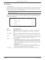
8.4.6 Manual set-up ................................................................................. 8 - 14
8.4.7 Automatic set-up ............................................................................. 8 - 14
WATCHDOG RELAY TEST ................................................................ 8 - 14
RL1 RELAY TEST .............................................................................. 8 - 15
RL2 RELAY TEST .............................................................................. 8 - 15
COMMUNICATIONS HARDWARE CHECK ....................................... 8 - 15
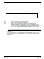
8.4.8 The 'S' Monitor ............................................................................... 8 - 16
S MONITOR ACCESS ..................................................................... 8 - 16
QUIT ............................................................................................. 8 - 16
HELP .............................................................................................. 8 - 16
DISPLAY BASIC MACHINE STATUS ................................................... 8 - 17
DISPLAY EXTENDED MACHINE STATUS ............................................ 8 - 17
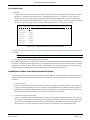
DIAGNOSTICS MENU ................................................................................... 8 - 18
MEMORY STATUS ........................................................................... 8 - 20
SHOW BOOT INFO ...................................................................... 8 - 20
DATE /TIME SET ............................................................................. 8 - 20
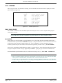
CHAPTER 9 SPECIFICATION ABD ORDER CODES ................................. 9 - 1
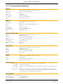
9.1 SPECIFICATION ........................................................................................ 9 - 2
9.1.1 General specification ........................................................................ 9 - 2
9.1.2 Backplane specification ..................................................................... 9 - 2
9.1.3 Connect module specification ............................................................. 9 - 3
9.1.4 Processor Module specification .......................................................... 9 - 4
9.1.5 Software specification ....................................................................... 9 - 5
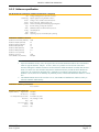
9.2 ORDER CODES ......................................................................................... 9 - 6
9.2.1 Instrument order code ........................................................................ 9 - 6
9.2.2 Spares and accessories ...................................................................... 9 - 7
9.3 COSHH ................................................................................................... 9 - 8
INDEX ........................................................................................INDEX - 1
Section i
Page i - 8
HA028225
Issue 3 Jly 04
PROCESSS SUPERVISOR HANDBOOK
GLOSSARY OF TERMS
Items in italics in the descriptions below also appear as glossary items in their own right
2500
ALIN
ALIN bridge
Application
ARCNET
Baud
Brown-out
Cold start
Cold Start time
Configuration
Control strategy
CIDR
COSHH
CSP
CSS
DRAM
Duplex
EDB
EEPROM
ELIN
EMC
Eurotherm Project Studio
e-Suite
FB
FBD
Function block
GSD file
Hot start
Hot & Cold start:
ICM
Idle
IP
iTools
HA028225
Issue 3 Jly 04
I/O sub-system for use with Process Supervisor units
Local Instrument Network (LIN) protocol on ARCNET
LIN to ALIN network link
A LIN database and associated SFCs
A single non-branching, masterless network, running at 2.5MBaud allowing peer-to-peer
communications and file transfer up to 100 metres.
Used to describe transmission speeds over communications links. (9600 baud = approximately 1000 ASCII characters per second)
A brown-out is a transient power variation or partial power failure severe enough to prevent
continuation of the process until the process supervisor has been re-initialised.
A Cold start is where the instrument starts with the last-loaded database loaded using either
default parameters or parameters held in the cold start parameter file. See also Hot Start
The Cold Start time is a pre-set duration, following power off, after which a Hot Start is not
possible, and a Cold Start must be initiated instead.
The process of specifying the components of an application.
A control strategy is the overall programmed function of the LIN database within an instrument, ready to act upon a real life process.
Classless Inter-domain Routing. A standard for IP addressing.
Control of Substances Hazardous to Health legislation
Cold Start Primary - the left-hand processor module. Applies to redundant mode systems only.
Cold Start Secondary - the right-hand processor module. Applies to redundant mode systems
only.
Dynamic Random Access Mamory
Twin synchronised processors capable of operating in redundant mode
External database
Electrically Erasable Programmable Read Only Memory
Local Instrument Network (LIN) protocol on Ethernet
Electro-magnetic compliance
A suite of programs for building, testing and configuring programs and systems for process
control and I/O.
A control/monitoring/configuration system for use with process supervisor units.
Function block.
Function Block Diagram - a programming language.
A unit of software that performs a named function. It can be linked to other function blocks to
build a LIN database and hence a control strategy for an instrument.
A GSD (Gerätestammdaten) file contains instrument parameter information, which a Profibus
master needs in order to communicate with the instrument.
After a power loss, the instrument attempts to re-start with the current database still loaded and
with all parameters and values for that application still at the values they held when processing
stopped. If the restart fails the processor enters an idle state.
After a power loss, the instrument attempts to re-start with the current database still loaded and
with all parameters and values for that application still at the values they held when processing
stopped. If the restart fails the processor attempts a cold start.
Inter-CPU Messaging for redundancy.
A state in which the processor module is powered up, but with an empty database. This state
is entered as a result of 'test' being selected as start-up mode, or if a hot start or cold start is
not successful.
Internet Protocol.
A Eurotherm utility for configuring networks of Eurotherm I/O controllers.
Section i
Page i - 9
PROCESS SUPERVISOR HANDBOOK
GLOSSARY (Cont.)
LIN
LIN database
LIN protocol
LINtools
Modbus®
Non-redundant mode
PAL
Primary
Processor module
Process variable
Profibus
PSU
Redundant mode
RFI
Secondary
Synchronised
SFC
Simplex
SLIN
Tepid Start
Test start
Section i
Page i - 10
Local Instrument Network, a Eurotherm proprietary system for networking process monitoring
and control instruments.
The LIN database is a set of software function blocks that constitute the control strategy of a
LIN instrument.
The communications protocol employed to control instruments linked by a LIN.
A Eurotherm utility for configuring networks of LIN instruments.
A proprietary communications protocol (Gould-Modicon Modbus RTU).
One or more processors running but not synchronised.
Programmable Logic Array.
In a Redundant mode system, the primary is that processor which is in control. The other
processor is called the secondary processor.
The process supervisor consists of a backplane fitted with one or two Processor Modules and a
connection module. 'Processor Module' should not be confused with Central Processor Unit
(CPU) which is electronics hardware contained within the Processor module.
Characteristics of a process - such as temperature, pressure and valve aperture - that can
change value.
A communications standard.
Power supply unit.
Two synchronised processor modules (the primary and secondary). The secondary processor
tracks the primary in every respect so that it can take command should the primary (or the
supply power to it) fail.
Radio frequency interference.
In a Redundant mode system, the primary is that processor which is in control. The other
processor is called the secondary processor and it continuously tracks the primary, so that it
can assume control should the primary fail.
During the start up sequence in redundant mode, once the primary processor is running, it
copies database and function block data to the secondary. Once this is complete, and the
database is running in both processor modules, the processor modules are said to be synchronised.
Sequential Function Chart. An SFC monitors key variables and parameters and, on the basis of
the values it finds, decides which route through a flowchart the application should follow.
A processor working alone i.e in non-redundant mode.
LIN protocol on a serial link (point-to-point).
Similar to a hot start, but with a only limited amount of database information.
Once started, the processor module enters an idle mode, with an empty data base loaded.
HA028225
Issue 3 Jly 04
PROCESS SUPERVISER HANDBOOK
CHAPTER 1 INTRODUCTION
The process supervisor is one part of a complete control system. The entire package is described in the Eurotherm
Project Studio User Guide and Tutorial HA261230 which includes a number of tutorial examples, to help users to
familiarise themselves with the software and hardware facilities available.
1.1 MANUAL CONTENTS
This manual is divided into the following chapters:
Chapter 1. Introduction
Chapter 2. Installation
Chapter 3. User Interface (explaining the front panel LEDs and switches)
Chapter 4. Start Up (step-by-step instructions on how to start up or re-start the instrument)
Chapter 5. Configuration (how to configure, or more typically re-configure, control strategy and communications
protocols on site, usually to match changes in the plant being controlled). (Initial configuration, to Customer Specification, is normally carried out prior to delivery.)
Chapter 6. Diagnostics (how to diagnose faults that could develop in the instrument, by recognising fault indications)
Chapter 7. Task Organisation and tuning
Chapter 8. Service
Chapter 9. Technical Specification and order codes
The contents of any other manuals in this binder are listed within those manuals.
1.2 OTHER INFORMATION SOURCES
For details of (LIN) based function blocks, their parameters and input/output connections refer to the LIN blocks reference section of the LIN product manual (HA082375U999) which explains how control strategy LIN blocks are
selected, interconnected etc. The creation and monitoring of databases and communications configurations is described in the Eurotherm Project studio documentation. The configuration of Sequential Function Charts (SFCs) is
described in the T500/550 LINtools User Guide (HA082377U005). Modbus and Profibus implementations are discussed in the Communications Manual (HA028014).
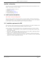
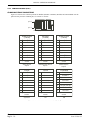
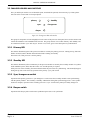
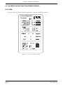
1.3 THE PROCESS SUPERVISOR UNITS
Process supervisor
Connect
ε
Processor
Power
24V
system
A
B
ε
Process supervisor
EUROTHERM
A
B
A
B
int
ext
Alarms
24V
rl2
in
A
B
int
ext
EUROTHERM
Alarms
rl1
battery
rl2
Comms
system
out
Power
rl1
battery
ε
Process supervisor
Processor
Comms
i/oA
in
EUROTHERM
out
A
B
tx
exp1
system
exp2
i/o
rx
i/o
exp1
A
B
tx
rx
exp2
i/oB
in
out
in
primary
out
primary
standby
sync
changeover
standby
sync
changeover
exp1
in
out
in
out
in
out
in
out
desync
exp2
rl1
-
rl2
wdog batt
+
-
alarms
+
+
rl1
24V
A
left processor
rl2
+
-
wdog batt
-
desync
Restart
wdog
+
hot
hot/cold
cold
test
+
halt
duplex
config
Restart
wdog
halt
duplex
hot
hot/cold
cold
test
config
24V
B
A
B
right processor
An Invensys company
An Invensys company
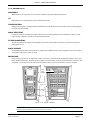
Figure 1.3 Connect module (left) and dual processor modules (centre and right) on the backplane
HA028225
Issue 2 Nov 03
Chapter 1
Page 1 - 1
PROCESS SUPERVISER HANDBOOK
1.3.1 Typical applications
The process supervisor is designed to control processing plants using distributed input/output modules, interconnected
using networks. A number of process supervisors can be networked together, allowing thousands of I/O points to be
monitored and controlled.
1.3.2 Features
The main features of the process supervisor are as follows
LIN
A LIN-based network using either ALIN or ELIN. This allows communications with I/O modules and the wider network via either a ‘daisy-chain’ configuration (ALIN only) or a central ALIN or ELIN ‘hub’. See Chapter 2, figure 2.5.
MODBUS
The Unit supports Modbus comms via the connect module exp1 (master) and exp 2 (slave) ports if so configured.
PROFIBUS.
The Unit supports Profibus communications via the connect module i/oB port.
REDUNDANT PROCESSOR MODULES
The processors can be set up for redundant or non-redundant operation. When operating in redundant (duplex) mode,
a high speed data link (ICM) between the primary and secondary processor units provides exact tracking of the control database, allowing bumpless takeover by the secondary unit should the primary processor fail.
Note: See the ‘Important Information’ leaflet (HA261399) for backwards compatibility details.
AUTOMATIC TAKE-OVER
Takeover of control by the secondary processor in the event of primary failure is automatic, with no loss of I/O states
and no need to re-initialise I/O points. Revalidation of all attached LIN nodes is automatic.
REDUNDANT POWER SUPPLY CONNECTION
Two independent power connectors for each processor unit, plus external battery for memory backup ensures full
redundancy. An internal battery supports the data in SRAM (if fitted) and the real-time clock for a minimum of 72
hours.
LIVE PROCESSOR REPLACEMENT
Live replacement of a failed processor can be carried out, with no wiring disconnections. The replacement unit loads
its strategy and current status from the active processor. Full hardware and software status indication allows rapid
verification and diagnostics.
DIAGNOSTICS
Automatic health checks, self-testing, and initialisation on power-up.
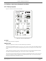
FRONT PANEL ANNUNCIATION.
Front panel LEDs are provided for communications and processor status. Control switches are also fitted on each
processor module.
CONTINUOUS HEALTH MONITORING
Extensive on-going diagnostics and health monitoring of communications and I/O status.
Chapter 1
Page 1 - 2
HA028225
Issue 2 Nov 03
PROCESS SUPERVISER HANDBOOK
1.3.2 FEATURES (Cont.)
WATCHDOG
Watchdog relay for each processor, with Connect module front-panel AND/OR connections.
I/O
Distributed I/O is networked using serial communications links.
CONFIGURATION.
Strategies and sequences configured/downloaded/monitored with Eurotherm Project Studio or the resident configurator (needs external terminal).
BLOCK STRUCTURE.
Continuous strategies are built up by interconnection of fixed function blocks from a comprehensive library of analogue and logic elements, common to all LIN based instruments.
ST USER ALGORITHMS
Special ACTION blocks support user-algorithms written in ST (Structured Text) and are well-suited to implement
plant logical devices.
BLOCK SUPPORT
All standard LIN data base function blocks are supported in redundant mode. Special diagnostic blocks are available
for hardware and software status reporting.
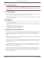
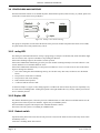
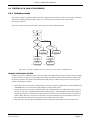
ENCLOSURES
Process supervisor units can be supplied in a range of enclosures, both wall-mounted and floor-standing. Power supplies, standard terminations, transmitter power supplies, and I/O modules can all be fitted within these enclosures, and
if required, a visual supervisor unit can be door mounted to allow a visual representation of process variables.
I/O
racks
(multiple)
Process
supervisor
Battery
unit
PSUs
Figure 1.3.2c Typical installations
Note: The process interface i/o modules can be mounted vertically as shown in the sides of the single bay
enclosure, or horizontally as shown in the two-bay version.
HA028225
Issue 2 Nov 03
Chapter 1
Page 1 - 3
PROCESS SUPERVISER HANDBOOK
This page is deliberately left blank
Chapter 1
Page 1 - 4
HA028225
Issue 2 Nov 03
PROCESS SUPERVISOR HANDBOOK
CHAPTER 2 INSTALLATION
This chapter presents safety and EMC information and describes the mechanical and electrical installation of the instrument. The main topics covered are as follows:
1.
2.
3.
4.
5.
Safety & EMC information (section 2.1)
Unpacking (section 2.2)
Mechanical layout (section 2.3)
Set-up switch definition (section 2.4)
Connections and wiring (section 2.5)
2.1 SAFETY AND EMC INFORMATION
Please read this section before installing the unit.
This unit meets the requirements of the European Directives on Safety and EMC as detailed on the Declaration of
conformity IA249986U610, a copy of which appears at the beginning of this manual. It is, however, the responsibility of the installer to ensure the safety and EMC compliance of any particular installation.
2.1.1 Installation requirements for EMC
This unit conforms with the essential protection requirements of the EMC Directive 89/336/EEC, amended by 93/68/
EEC. It also satisfies the emissions and immunity standards for industrial environments.
To ensure compliance with the European EMC directive certain installation precautions are necessary as follows:
1 General guidance. For general guidance refer to the Eurotherm Process Automation EMC Installation Guide
(Part No. HG083635 U001).
2 Relay outputs. When using relay outputs it may be necessary to fit a filter suitable for suppressing conducted
emissions. The filter requirements will depend on the type of load.
3 Routing of wires. To minimise the pick-up of electrical noise, low voltage DC connections and sensor input
wiring should be routed away from high-current power cables. Where it is impractical to do this, shielded cables
should be used, with the shield grounded at both ends.
HA028225
Issue 2 Nov 03
Chapter 2
Page 2 - 1
PROCESS SUPERVISOR HANDBOOK
2.1.2 Installation safety requirements
PERSONNEL
Installation must be carried out only by authorized personnel.
HAZARDOUS VOLTAGES
Caution
In order to comply with the requirements of BS EN61010, the voltage applied across I/O terminals may not exceed
those terminals’ isolation voltage (see Chapter 9 for specification). For terminals specified as having no isolation, the
maximum permissible voltage is 30V ac or 50 V dc,
CONDUCTIVE POLLUTION
Electrically conductive pollution (e.g. carbon dust, water condensation) must be excluded from the enclosure in which
the unit is mounted. To ensure the atmosphere is suitable, an air filter should be installed in the air intake of the enclosure. Where condensation is likely, a thermostatically controlled heater should be included in the enclosure.
VENTILATION
Ensure that the enclosure or cabinet housing the unit provides adequate ventilation/heating to maintain the operating
temperature of the unit within the limits indicated in the Specification (see Chapter 9).
PRECAUTIONS AGAINST ELECTROSTATIC DISCHARGE
Caution
Circuit boards inside the units contain components which can be damaged by static electrical discharge. Before any
circuit board is removed or handled it should be ensured that the handler, the instrument and the circuit board are all
at the same potential.
2.1.3 Keeping the product safe
To maintain the units in a safe condition, observe the following instructions.
MISUSE OF EQUIPMENT
Note that if the equipment is used in a manner not specified in this handbook or by Eurotherm Process Automation,
the protection provided by the equipment may be impaired.
SERVICE AND REPAIRS
Except for those parts detailed in Chapter 8, the Process Supervisor has no user-serviceable parts. Contact the nearest
manufacturer’s agent for repair.
2.2 UNPACKING
The instrument and accessories should be carefully unpacked and inspected for damage. The original packing materials should be retained in case re-shipment is required. If there is evidence of shipping damage, the supplier or the
carrier should be notified within 72 hours and the packaging retained for inspection by the manufacturer’s and/or
carrier’s representative.
Chapter 2
Page 2 - 2
HA028255
Issue 2 Nov 03
PROCESS SUPERVISOR HANDBOOK
2.2.1 Handling precautions
Caution
Circuit boards inside the units contain components which can be damaged by static electrical discharge. Before any
circuit board is removed or handled it should be ensured that the handler, the instrument and the circuit board are all
at the same potential.
2.2.2 Package contents
Note: The process supervisor may form part of a larger assembly, and/or may be housed in a floor or wall-mounted
enclosure. If so, the documentation that accompanied those items should be referred-to.
The package contents should be checked against the order codes, using the labels on the components. Order codes are
listed in Chapter 9 of this handbook.
PRODUCT LABELLING
Product labelling includes:
1. Sleeve label. On the outside of the processor and connect module sleeves, showing the model number , serial
number, and hardware build level.
2. Backplane label. On the edge of the backplane, showing the model number, serial number, and hardware build
level.
3. Software labels showing version and issue numbers.
4. Flash memory card label showing version and issue number.
5. Safety earth symbol adjacent to safety earth stud.
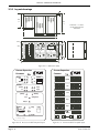
2.3 MECHANICAL LAYOUT AND INSTALLATION
Figure 2.3.1a shows two processor modules and a connect module mounted on the backplane. Remote I/O modules
(described in the 2500 Controller User Manual, HA026178) are connected to the processor modules using the i/oA
and/or i/oB communications sockets of the connection module. Figures 2.3.1b and 2.3.1c show front views of the
modules.
When only a single processor is fitted, it is recommended that the blanking plate supplied be fitted to the vacant slot,
to maintain EMC emission/immunity specifications.
The processor modules can operate either independently (simplex), or else in ‘redundant’ (duplex) mode in which case
one of the processors acts as a primary, backed up by the other processor (the secondary), which can take over from
the primary at any time.
Power is supplied to each processor module by one or two external 24V (nom.) power supplies. The two supplies are
effectively OR’d together within the processor module, so they can run in parallel, thus ensuring that the processor
continues to operate even if one of the supplies fails.
A separate plug is available to allow the connection of an external battery (2.4 to 5.0 V), to maintain the real-time
clock (RTC) during shut down. An internal battery can be fitted to maintain the RTC for a minimum of 72 hours.
Chapter 8 gives installation/replacement procedures for the internal battery, and Chapter 9 gives details of suitable
batteries, both internal and external.
HA028225
Issue 2 Nov 03
Chapter 2
Page 2 - 3
PROCESS SUPERVISOR HANDBOOK
2.3.1 Layout drawings
8.5
150
±1
210
±1
Tolerance = ± 0.5mm,
except where shown
otherwise
120
120
120
241±1
362±1
ε
Process supervisor
EUROTHERM
Processor
Power
A
B
in
out
in
out
in
out
B
int
ex
t
ε
A
B
in
out
in
out
in
out
battery
EUROTHERM
Power
rl2
battery
Comms
system
i/o
exp1
A
B
tx
rx
A
B
in
t
ex
t
A
B
ε
10
Alarms
rl2
Earth stud
(M4)
system
exp2
EUROTHERM
rl1
24V
Comms
i/oA
Process supervisor
Processor
Alarms
rl1
24V
system
ø12
A
i/o
exp1
tx
rx
exp2
i/oB
primary
primary
standby
sync
changeover
standby
sync
changeover
exp1
desync
exp2
in
rl1
+
-
Restart
out
rl2
in
wdo batt
g
24V
+
-
A
B
left processor
alarms
+
rl1
+
-
24V
desync
wdog
hot
hot/cold
cold
test
out
rl2
180
Process supervisor
Connect
125
ø6.5
config
Restart
wdog
hot
hot/cold
cold
test
50
config
wdog batt
A
duplex
halt
+
-
halt
duplex
20
B
An Invensys company
right processor
10
An Invensys company
382
402
Figure 2.3.1a Dimensions (mm)
Process Supervisor
Process Supervisor
Connect
Processor
Power
A
Alarms
B
24V
rl1
system
int ext
battery
rl2
A
B
in
out
in
out
Comms
A
B
tx
rx
i/o
B
in
out
in
out
in
out
in
out
i/oA
exp1
system
A
exp2
primary
i/oB
standby
sync
changeover
exp1
desync
Restart
hot
hot/cold
cold
test
halt
wdog
in
out
in
out
exp2
config
duplex
rl1
rl2
+
-
Figure 2.3.1b Processor module front panel layout
Chapter 2
Page 2 - 4
+
-
A
An Invensys company
alarms
wdog batt
left processor
B
rl1
+
24V
A
rl2
wdog batt
+
B
right processor
Figure 2.3.1c Connect module front panel layout
HA028255
Issue 2 Nov 03
PROCESS SUPERVISOR HANDBOOK
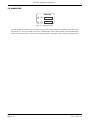
2.3.2 Removal of modules
It is recommended that power be removed and all wiring be disconnected from the connection module, before it is
removed from the backplane.
Although Processor Modules are designed to be removed/replaced with power applied, the life of the connector will
be maximised if they are removed with power off.
Note: Figure 2.3.2 shows a connection module. The procedure is identical for processor modules.
To remove a module:
1 Remove wiring, by disconnecting connectors
2 Unscrew both retaining screws (anticlockwise) to jack the unit out of its connector.
3 Lift the unit off its retaining catch.
3 Lift unit off the catch
2 Undo jacking
screws
1 Remove wiring
Figure 2.3.2 Module removal
2.3.3
1
Fitting of modules
Lift the module onto its retaining catch, and gently push the module towards the backplane to mate the connector.
Caution
Do not force the unit onto its connector or damage will occur
2
Re-engage and tighten both retaining screws a few turns each at a time, to a maximum torque of 2.5 Nm.
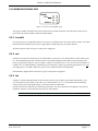
2.4 BACKPLANE SWITCHES
2.4.1 Location
HA028225
Issue 2 Nov 03
Chapter 2
Page 2 - 5
PROCESS SUPERVISOR HANDBOOK
The backplane switches for setting communications addresses and for selecting options on and off are revealed (figure
2.4.1) when the right-hand processor module or the cover plate is removed from the back plane.
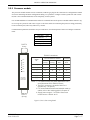
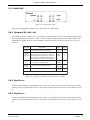
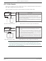
2.4.2 Switch functions
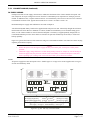
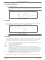
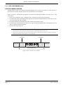
SW1: LIN ADDRESS SETTING SWITCH
Figure 2.4.2a below shows the LIN address-setting switch SW1 (located on the backplane as shown in figure 2.4.1).
The figure shows a sample set up for address pair 7A/7B.
Whenever there are two processor modules fitted to the backplane and working in non-redundant mode, the left-hand
processor unit is allocated the even address (Bit 0 = 0) and the right-hand processor is allocated the odd address (Bit 0
= 1).
When working in redundant mode, the primary processor is initially the left-hand (even address) unit and the secondary is initially the right-hand (odd address) unit. Should it prove necessary for the secondary to take over, and become
the primary, it will also take over the even address.
Note: In redundant mode, a single processor module running on its own in the chassis never adopts the odd
address as it is always the primary controller. It is strongly recommended that this odd address be kept ‘spare’
and not allocated to another instrument on the same LIN segment. This will avoid address clashes if a second
processor module is subsequently added to the backplane.
Figure 2.4.2a LIN address setup example
Sw1: LIN Address
7
On (1)
A/B
0 1 1 1 1 0 1X
MSB
SW1 ADDRESS
MSB
ON
0
1
1
1
1
Push left
for 'ON'
OFF
0
LSB
8
7
SRD 6
MDB 5
4
ON
3
2
WDR 1
Bit 7
Bit 1
1
OFF
LSB
X
SW2 OPTIONS
Example of how to set address pair 7A/7B
(Bit 0 automatically set to 0 (thus 7A) for left
processor and to 1 (7B) for right processor)
Addresses 00, FE and FF are reserved and
MUST NOT be used.
Binary Hex
0000
0001
0010
0011
0100
0101
0110
0111
1000
1001
1010
1011
1100
1101
1110
1111
0
1
2
3
4
5
6
7
8
9
A
B
C
D
E
F
Figure 2.4.1 Location of backplane switches
Chapter 2
Page 2 - 6
HA028255
Issue 2 Nov 03
PROCESS SUPERVISOR HANDBOOK
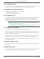
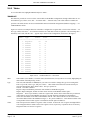
2.4.2 BACKPLANE SWITCH FUNCTIONS (Cont.)
Sw2: OPTIONS SWITCH
Figure 2.4.2b, below, shows the Options switch SW2 (located on the backplane as shown in figure 2.4.1, above).
Off (0)
8
7
SRD 6
MDB 5
4
3
2
WDR 1
Sw2 Options
8
7
6
5
4
3
2
1
Not used
Not used
Redundancy disable
Modbus enable
Not used
Not used
Not used
Watchdog retry enable
Figure 2.4.2b Option switch layout
WDR (WATCHDOG RETRY)
Setting this switch segment ‘on’ (slide to the left) causes the processor to try to start again after any watchdog failure.
Setting the segment ‘off’ (slide to the right) disables the re-try and the processor will need manual restart after a
watchdog failure.
MDB (MODBUS ENABLE)
Setting this switch segment ‘on’ (slide to the left) enables Modbus communications (if fitted). Setting the segment
‘off’ (slide to the right) disables Modbus Communications (see note 2 below).
SRD (REDUNDANCY DISABLE)
Setting this switch segment ‘off’ (slide to the right) selects redundant mode, with two processors defined initially as
‘primary’ (left-hand processor) and ‘secondary’ (right-hand processor). Setting the segment ‘on’ (left) disables redundancy mode, and both processors (if two are fitted) run independently.
Notes: Sequential Flow Chart programs cannot be run in redundant mode.
HA028225
Issue 2 Nov 03
Chapter 2
Page 2 - 7
PROCESS SUPERVISOR HANDBOOK
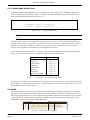
2.5 CONNECTIONS AND WIRING
Units may be supplied mounted in an enclosure, together with the appropriate termination assemblies — either fitted
in the enclosure or supplied in kit form. Please refer to the documentation that was supplied with the enclosure for
details of the connections and wiring.
If you are assembling the system yourself, you should refer to the relevant I/O Modules Reference Manual, the LIN/
ALIN/ELIN Installation & User Guide (HA082429U005) and the Communications Manual (HA028014) for advice on
connections and wiring to the I/O modules.
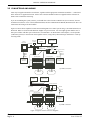
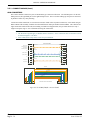
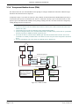
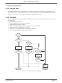
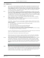
Figure 2.5 below shows simplified overall connection diagrams for a control system using a) an ALIN hub and b) an
ELIN hub. Hubs are useful for individual line lengths of up to 100 metres. For line lengths greater than this one or
more pairs of hubs with fibre-optic connections is recommended. As detailed later in this chapter, it is also possible
(with ALIN systems) to connect local items together in series, using a daisy-chain technique, rather than in a star layout using a Hub.
ALIN Hub
(ArcNet)
Visual
supervisor
PC
Project studio
PC
SCADA
ALin
Terminator
ALin
ALin
Process supervisor
ALin
ALin
I/O A
(Unused ports need terminators)
I/O B
EIA232
EIA232
2RX
1TX
!RX
EXE
PWR
UNIVERSAL
INTERFACE
CONVERTER
comms
Isolator
PSU and relays
2TX
2RX
1TX
!RX
EXE
Profibus
EIA232
I/O sub-system
Profibus
2TX
PWR
UNIVERSAL
INTERFACE
CONVERTER
I/O sub-system
Configuration
Terminal
comms
Isolator
EIA232
Configuration
Terminal
I/O sub-system
I/O sub-system
Terminator
a) ALIN connection
Process
Process
PC
Project studio
PC
SCADA
Process supervisor
Ethernet
(ELIN) Hub
Profibus
I/O sub-system
Profibus
EIA232
PSU and relays
2TX
2RX
1TX
!RX
EXE
PWR
UNIVERSAL
INTERFACE
CONVERTER
comms
Isolator
I/O sub-system
EIA232
I/O sub-system
I/O sub-system
Configuration
Terminal
Terminator
b) ELIN connection
Process
Process
Figure 2.5 Typical overall connection diagrams
Chapter 2
Page 2 - 8
HA028255
Issue 2 Nov 03
PROCESS SUPERVISOR HANDBOOK
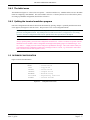
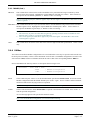
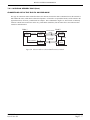
2.5.1 Connect module
The RJ45 connectors on the front panel can be wired for ELIN, ALIN, Modbus or Profibus use, according to specification at time of order. The pairs of connectors on the left hand side of the module are assigned to the left hand processor; the right hand connectors to the right-hand module. Each pair of connectors (except system A/B) is wired in
parallel to provide for easy daisy chaining.
Plug-in modules to provide biassing components to terminate the transmission line, are available from the manufacturer. Such terminators are required only at the final node of the transmission line.
Note: Terminators are not required for ELIN systems
Process Supervisor
Connect
ELIN
system
A
B
ALIN
A
B
in
out
in
out
in
out
in
out
i/oA
in
out
in
out
Profibus
i/oB
Modbus
Master
exp1
in
out
Modbus
Slave
exp2
in
rl1
out
rl2
+
-
alarms
wdog batt
+
-
A
left processor
B
rl1
+
24V
A
rl2
wdog batt
+
B
right processor
Figure 2.5.1a Connect module front panel
HA028225
Issue 2 Nov 03
Chapter 2
Page 2 - 9
PROCESS SUPERVISOR HANDBOOK
2.5.1 CONNECT MODULE (Cont.)
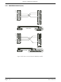
COMMUNICATIONS CONNECTORS
Figure 2.5.1b shows the connector pinouts for Modbus (EIA422 or EIA485), Profibus and LIN standards. For the
pinout for the processor CONFIG port, see section 2.5.2 below.
pin 8
pin 1
RJ 45 plug: View on underside
EIA422/485
(5-wire)
EIA485
(3-wire)
EIA422/485
(5-wire)
1
TxB
1
EIA485B
1
RxB
2
TxA
2
EIA485A
2
RxA
3
Signal common
3
Signal common
3
Signal common
4
Not used
4
Not used
4
Not used
5
Not used
5
Not used
5
Not used
6
Signal common
6
Signal common
6
Signal common
7
RxB
7
Not used
7
TxB
8
RxA
8
Not used
8
TxA
Plug shroud to cable
screen
Slave device
exp1/2
Plug shroud to cable
screen
Master/slave device
exp1/2
Plug shroud to cable
screen
ELIN
ALIN
Profibus
Master device
exp1/2
1
Tx+
1
Not used
1
EIA485 B
2
Tx-
2
Not used
2
EIA485 A
3
Rx+
3
Not used
3
Signal common
4
Not used
4
ALIN A
4
Not used
5
Not used
5
ALIN B
5
Not used
6
Rx-
6
Not used
6
+5V (for pull-up)
7
Not used
7
Not used
7
Not used
8
Not used
8
Not used
8
Not used
Plug shroud to cable
screen
Plug shroud to cable
screen
Plug shroud to cable
screen
SystemA
ioA
ioB
Figure 2.5.1b Pinout for Connect module RJ45 type plugs
Chapter 2
Page 2 - 10
HA028255
Issue 2 Nov 03
PROCESS SUPERVISOR HANDBOOK
2.5.1 CONNECT MODULE (Cont.)
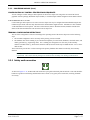
ELIN CONNECTORS
The Connect module contains two pairs of RJ45 type connectors called system A/B. The left-hand pair is for the lefthand processor; the right-hand pair for the right-hand processor.
Note: System B connectors not supported at time of print.
Connection with an ELIN hub is made using a RJ45-to-RJ45 cable assembly. When connecting to the ELIN Hub, a
‘straight-through’ cable is used. When connecting directly, a ‘cross-over’ cable is required. Fig 2.5.1c shows the connections.
SHROUD/SCREEN
Tx+
1
Tx-
2
Rx+
3
White/Orange
1
2
Orange
White/green
3
Blue
4
4
Blue/white
5
Rx-
5
6
6
Green
White/Brown
7
8
7
8
Brown
(8-Way RJ45)
(8-Way RJ45)
Screen
White/Orange
Orange
White/green
Blue
Blue/white
Green
White/Brown
a) Straight-through version
Brown
View on rear of connectors
(Straight-through cable)
1
8
1
8
SHROUD/SCREEN
White/Orange
1
2
1
2
Orange
White/green
3
3
Blue
4
4
Blue/white
5
6
7
8
5
6
Green
White/Brown
7
8
Brown
(8-Way RJ45)
(8-Way RJ45)
Screen
White/Orange
Orange
White/green
Blue
Blue/white
Green
White/Brown
b) Cross over version
Brown
8
1
View on rear of connectors
(Cross over cable)
8
1
Figure 2.5.1c ELIN connection details
HA028225
Issue 2 Nov 03
Chapter 2
Page 2 - 11
PROCESS SUPERVISOR HANDBOOK
2.5.1 CONNECT MODULE (Cont.)
ALIN CONNECTORS
The Connect module contains two pairs of ALIN RJ45 type connectors called i/oA. The left-hand pair is for the lefthand processor; the right-hand pair for the right-hand processor. The two sockets making up each pair are connected
in parallel to allow easy daisy-chaining.
Connection with an ALIN hub, or a PCI ArcNet card (also fitted with 8-way RJ45 connectors) can be made using an
RJ45-to-RJ45 cable assembly available from the manufacturer under part number S9508-5/2RJ45. This cable has all
eight connections made at both ends, thus making it suitable for all applications, not just ALIN which uses only a
single twisted pair). Fig 2.5.1d is a schematic showing the connections.
Notes:
1 The Rx and Tx legends apply to Modbus master connectors. Slave connections have Tx and Rx reversed
as shown in figure 2.5.1b above.
2 Wire colours shown may not be correct for your cableform
SHROUD/SCREEN
TxB (5 -wire)
EIA485B (3-wire)
1
TxA (5-wire)
EIA485A (3-wire)
2
0V
White/Orange
1
2
Orange
White/green
3
3
Blue
(ALIN phase A)
4
4
Blue/white
(ALIN phase B)
5
0V
6
RxB (5-wire)
7
RxA (3-wire)
8
5
6
Green
White/Brown
7
8
Brown
(8-Way RJ45)
(8-Way RJ45)
Screen
White/Orange
Orange
White/green
Blue
Blue/white
Green
White/Brown
Brown
8
1
View on rear of connectors
8
1
Figure 2.5.1d S9508-5/2RJ45 connection details
Chapter 2
Page 2 - 12
HA028255
Issue 2 Nov 03
PROCESS SUPERVISOR HANDBOOK
2.5.1 CONNECT MODULE (Cont.)
ELIN HUBS
The use of standard ‘off-the-shelf’ Ethernet hubs is recommended, using ‘Straight-through’ cables (figure 2.5.1c). For
further details, the LIN/ALIN/ELIN installation and user guide (HA082429U005) should be referred to.
ALIN HUBS (ACTIVE)
Figure 2.5.1e shows a simple ALIN hub layout, and figure 2.5.1f a daisy-chain layout. The hub layout is preferred in
cases where the integrity of the ALIN network is considered to be susceptible to lengths of daisy-chain becoming
inoperative due to cable breakage or individual hardware faults.
ALIN Network
Process supervisor
ALin
ALin
Terminator
Profibus
PC
Eurotherm
Project Studio
I/O A (Unused ports
I/O B need terminators)
Remote I/O
Terminator
Figure 2.5.1e ALIN Hub layout
ALIN Hub
(Arcnet)
ALin network
Terminator
Terminator
ALin
ALin
Profibus
PC
ALin
Eurotherm
Terminator
Project Studio
Process supervisor
I/O A (Unused ports
I/O B need terminators)
Remote I/o
Terminator
Figure 2.5.1f Daisy-chain layout
HA028225
Issue 2 Nov 03
Chapter 2
Page 2 - 13
PROCESS SUPERVISOR HANDBOOK
2.5.1 CONNECT MODULE (Cont.)
ALIN HUBS (PASSIVE)
Mechanically, a passive ALIN hub consists of a metal box with 12 RJ-45 type connectors and one RJ11 connector (for
earlier equipment). Electronically, the hub consists of a resistor network designed to allow each of the 12 ports to be
connected to a single unterminated- node, using a cable up to three metres in length. Cable termination is provided by
each port, and vacant ports must be left unterminated. This system ensures survival with one port short circuited and
any number (up to the maximum) of open-circuit ports.
DAISY-CHAIN LAYOUT
This method of connection is the preferred method where the integrity of the network is certain. Further details are to
be found in the LIN/ALIN/ELIN Installation and user guide HA082429U005.
CABLING
Shielded RJ45 connectors and screened Category 5 cables are widely available. Note, however, that specifications
vary and not all components are suitable for reliable ALIN operation. In view of the problems that can arise with
inadequate cabling, it is strongly recommended that ready-made interconnecting cables are ordered from the manufacturer.
Chapter 2
Page 2 - 14
HA028255
Issue 2 Nov 03
PROCESS SUPERVISOR HANDBOOK
2.5.1 CONNECT MODULE (Continued)
DC SUPPLY WIRING
Each processor has two 24V supply connections (A and B) near the bottom of the Connect module front panel. The
unit will operate on any dc voltage between 18V and 36V at a maximum power requirement of 50W per processor
module. In addition to this, a separate connector allows an external battery of between 2.5 and 5.0V to be connected
to maintain the real-time clock. Typical drain currents are 0.2 mA at 2.5V and 0.3 mA at 3.4V.
Recommended power supply units and batteries are listed in Chapter 9.
A nickel/metal-hydride battery board can be supplied inside each processor unit. When fully charged this will maintain the Real-time clock data for a minimum of 72 hours, should an external battery not be available during power
down, or if the Connect module is removed from the backplane. The battery is supplied partially charged, but it is
recommended that the processor unit in which it is fitted be left powered continuously for 48 hours, to ensure full
backup capability.
Figure 2.5.1g shows the locations of the connectors and gives recommended conductor sizes based on current carrying
capability and connector capacity.
1
2
Caution
Neither the positive nor the negative supply line may exceed 40V peak, with respect to Safety Earth
potential.
Should the supply voltage fall below 18 Volts during startup (caused, for example by current limiting on
the Power supply unit), the processor will fail to start successfully. It will then attempt to restart, and
enter a repeating cycle. Damage will occur to the unit if this cycle is allowed to continue.
FUSES
All positive supply lines must incorporate a fuse. Suitable types are 3A Type T for 24 Volt supplies and 0.5V Type T
for each external battery fitted.
exp2
in
out
in
– ++
rl1
rl2
wdog batt
+
-
– +
alarms
+
-
rl1
rl2
+
-
24V
A
out
+
wdog batt
+
-
24V
B
A
left processor
B
right processor
Recommended wire sizes
DC supply (single wire):
0.2mm2 to 2.5mm2
Relays /battery(single wire): 0.14mm2 to 1.5mm2
(20 awg to 14 awg)
(25 awg to 16 awg)
Fuse types (fuses to be fitted in positive supply line)
24V supply = 3A Type T; External battery = 0.5A Type T
Figure 2.5.1g DC and relay connection details
HA028225
Issue 2 Nov 03
Chapter 2
Page 2 - 15
PROCESS SUPERVISOR HANDBOOK
2.5.1 CONNECT MODULE (Cont.)
RELAY WIRING
There are three relays associated with each processor module, and the common
and normally open terminals of these relays are wired to the front of the Connect
module as shown in figures 2.5.1h and 2.5.1i. The contact ratings (resistive loads)
for the relays are 30V ac / 50V dc at 0.5A.
Relay
(Power off
state)
Com
NO
Rl1, Rl2
or wdog
The operational strategy of relays 1 and 2 (rl1 and rl2 respectively) is entirely
software controlled and is set up during configuration.
The watchdog relay is under hardware control; this hardware making a number of
health checks, before operating the relay. If during operation one of the health
check fails, the relay goes into its alarm (power-off) state. See Chapter 3: User
Interface for full details of the watchdog system.
Coil energisation
under software
control
Figure 2.5.1h Relay wiring
The relays can be wired in series or in parallel. When in parallel, both Processors have to fail, before the alarm becomes valid. When in series, the alarm becomes valid if either processor fails. Figure 2.5.1i shows the relays wired in
series to a 24V dc ‘healthy’ lamp. Figure 2.5.1j shows a parallel configuration, using an auxiliary relay to display
both healthy and warning states.
Note: For all relays, the common and normally open contacts are open circuit during power-off, and remain so
for some seconds at power-up, until software control has become established. After that, the contacts are
short circuit when the relay coil is energised, and open-circuit when the coil is not energised.
'Healthy' lamp
(12 Watts max.)
+24V dc
0V
wdog
alarms
left processor
wdog
right processor
Figure 2.5.1i Example wiring for watchdog relays in series
+24V dc
+240V ac
(Line)
Mains relay
Com
NO
wdog
alarms
Healthy
NC
Fail
wdog
0V
left processor
right processor
Neutral
Figure 2.5.1j Example wiring for watchdog relays in parallel
Chapter 2
Page 2 - 16
HA028255
Issue 2 Nov 03
PROCESS SUPERVISOR HANDBOOK
2.5.2 Processor module
The processor module contains one user connection, an RJ11-type plug for the connection of a configuration terminal
for on-line monitoring and minor configuration editing. It is possible to configure a whole system from such a terminal, but is not recommended because of the complexity of most systems.
It is recommended that a Communications isolator be connected between the processor module and the terminal. Figure 2.5.2a gives a pinout for such a unit. Figure 2.5.2b shows cables for connecting the processor config port directly
to a PC’s EIA232 port, both 9-way and 25-way versions.
Communications parameters should be set up as listed below, from the Properties/Connect-to/Configure connection
menu:
Baud Rate .... 9600
Nº of data bits .... 7
Nº of start bits .... 1
Parity .... Even
Nº of stop bits .... 1
PORT 2
6-way
EIA232 Connections
2TX
Signal
etc.
2RX
Communications isolator
Processor
Port 1
(8-way)
Port 2
(6-way)
Port 1
RJ11
Config Port
RJ11
1TX
RX Input
3
3
5
5
!RX
TX Output
1
1
4
4
Signal ground
6
6
3
3
RTS
5 (input)
Supply +
7
Supply +
8
EXE
PWR
UNIVERSAL
INTERFACE
CONVERTER
PORT 1
(8-way)
Notes: 1 For isolators with a DIP switch adjacent to Port 2,
set all elements Off for EIA232 Comms.
2 The RJ11 connector is in parallel with Port 1
(Signals only - not power)
3 For recommended isolators and suitable made-up
cables, refer to the ordering guide in Chapter 10.
4 Supply power range is 7 to 35Vdc. Worst case
inrush current = 660mA at 4V.
Figure 2.5.2a Isolator wiring details
HA028225
Issue 2 Nov 03
Chapter 2
Page 2 - 17
PROCESS SUPERVISOR HANDBOOK
2.5.2
PROCESSOR MODULE (Cont.)
(N.C.)
1
1
(N.C)
(N.C.)
2
2
Rx
0V
3
3
Tx
Tx
4
4
DTR
Rx
5
5
0V
(N.C.)
6
6
DSR
7
RTS
8
CTS
9
(N.C)
(6-Way RJ11 Male
to Processor module)
9-Way D-type socket
(To PC RS232 port)
6
1
5
9
1
REAR VIEW
(N.C.)
1
1
(N.C.)
2
2
Tx
0V
3
3
Rx
Tx
4
4
Rx
5
5
(N.C.)
6
6
7
(6-Way RJ11 Male
to Processor module)
0V
25
25-Way D-type socket
(To PC RS232 port)
6
1
REAR VIEW
1
14
7
13
25
Figure 2.5.2b Direct connection between CONFIG port and PC
Chapter 2
Page 2 - 18
HA028255
Issue 2 Nov 03
PROCESS SUPERVISOR HANDBOOK
2.5.2
PROCESSOR MODULE (Cont.)
CONFIGURATION OF CONTROL STRATEGIES AND SEQUENCES
You can configure control strategies and sequences for the Process Supervisor using either an external PC-based
graphical software package (Eurotherm Project Studio), or with the simpler inbuilt configurator and a dumb terminal.
EUROTHERM PROJECT STUDIO
Control strategies and sequences to be run in a Process Supervisor may be configured and downloaded using the Eurotherm Project Studio, which is fully described in the documentation supplied with it. Information is also available
via the Eurotherm network explorer. The LIN Product Manual (Part no. HA082375U999) should be consulted for
details of the function blocks that can run in the Process Supervisor.
TERMINAL CONFIGURATOR RESTRICTIONS
The use of the configurator is restricted according to the operating mode of the Process Supervisor in the following
ways:
1. The terminal configurator can be used only on the primary processor module.
2. The database must not be running if you want the full capability to create blocks, databases, edit field values, and
modify pool data (e.g. engineering units). If it is running, the configurator can write only to the normally
runtime-writeable fields: e.g. block names cannot be edited, but new blocks may be added and new ‘wires’ can be
made on-line.
These restrictions prevent files or edits occurring in the primary database that cannot be tracked by the secondary
database.
Note: When the database is started after the terminal configurator has been used, an automatic database save
is performed. This ensures that any changes are notified to the secondary CPU during synchronisation.
2.5.3 Safety earth connection
As shown in figure 2.3.1a, an M4 earth stud connection is provided on the back plane metalwork. This stud should be
bonded to a good local earth using multistrand tri-rated 1.5mm2 (21A) green/yellow earth cable, with ring terminals
for security.
HA028225
Issue 2 Nov 03
Chapter 2
Page 2 - 19
PROCESS SUPERVISOR HANDBOOK
2.5.4 Transparent Modbus Access (TMA)
This feature allows the use of the Eurotherm iTools package to configure Model 2500 controllers without having to
disconnect them from the Process Supervisor.
As depicted in figure 2.5.4, below, the 2500s are ‘daisy-chained’ from the Instruments’s Modbus Master port (Exp 1)
or the Profibus port (I/O B) via an EIA422 link. The PC is connected to the Exp 2 port via an EIA232 link, or to the
System A port via an Ethernet link. With the iTools package running on the PC, the 2500s can then be configured by
‘talking through’ the Process Supervisor.
Notes:
1. In order for TMA to work, the database must contain a Gateway file (.GWF) with the same name as the
database file (.dbf).
2. If the Profibus port is used, the 2500 unit(s) must support Profibus DPv1.
3. Instead of using PC/iTools via an occasional EIA232 link, a SCADA facility can be used via a permanent
EIA422 (exp2 port) or Modbus TCP link (System A port).
4. PC/iTools can also be connected to the Modbus port, but needs an EIA422/485 convertor. For an occasional link it is normally considered more convenient to use the CFG port on the front panel as described
above.
5. For more information refer to the iTools User Manual (part no. HA026179).
OR
iTools
Modbus
(Master)
Exp
2
iTools
Ethernet
TCP/IP
Process Supervisor
System
A
Modbus switch
Modbus switch
Profibus (DCM) (Master)
Note:
The Modbus switches are controlled via the _system.opt file
as described in the Comms
Manual HA028014
I/O B
Exp 1
Modbus (DCM)
(Master)
2500 (Slave)
2500 (Slave)
2500 (Slave)
2500 (Slave)
Figure 2.5.4 TMA schematic
Chapter 2
Page 2 - 20
HA028255
Issue 2 Nov 03
PROCESS SUPERVISOR HANDBOOK
CHAPTER 3 USER INTERFACE
3.1 INTRODUCTION
This chapter describes the functions of the processor module LEDs and switches.
As shown in figure 3.1, the items are arranged in groups on the processor module front panel, and each group is described in turn below. Table 3.1 (below) is a concise list of the LEDs and their functions.
Process Supervisor
Processor
Section 3.3
Section 3.2
Section 3.4
Section 3.5
Section 3.6
Figure 3.1 Processor module front panel
HA028225
Issue 2 Nov 03
Chapter 3
Page 3 - 1
PROCESS SUPERVISOR HANDBOOK
3.1 INTRODUCTION (Cont.)
Alarms
Power
Diagnostic
Value (Ch. 6)
Power A
Green...................... Main power input valid
Off........................... Main power input failed
Power B
Green...................... Auxiliary power input valid
Off........................... Auixiliary power input failed
backup ext
Green...................... External battery power valid Off until start-up
Off........................... External battery power failed
complete
backup int
Green...................... Internal battery power valid Off until start-up
Off........................... Internal battery power failed
complete
rl1
rl2
System A
Comms
System B
I/O A
I/O B
Exp1 Tx / Rx
Yellow..................... Alarm active
Off........................... Alarm not active
Yellow..................... Alarm active
Off........................... Alarm not active
08
04
Green...................... System A communications valid
Red......................... System A communications hardware failure
Flashing Red/Off..... System A communications cable fault
Off........................... System A communications not in use
Green...................... System B communications valid
Red......................... System B communications hardware failure
Flashing Red/Off..... System B communications cable fault
Off........................... System B communications not in use
Green...................... I/O A communications valid
Red......................... I/O A communications hardware failure
Flashing Red/Off..... I/O A communications cable fault
Off........................... I/O A communications not in use
Green...................... I/O B communications valid
Flashing Green/off.. Remote unit fault (Profibus comms. only)
Red......................... I/O B communications hardware failure
Flashing Red/Off..... I/O B communications cable fault
Off........................... I/O B communications not in use
Intermittent yellow....Communications taking place
Rx = 20
Tx = 10
Exp2 Tx / Rx
Startup
Primary
Standby
wdog
Duplex
Intermittent yellow... Communications taking place
Rx = 80
Tx = 40
Green...................... This CPU is primary
Off........................... This CPU is not primary
Flashing.................. Powered up but no database is running
Yellow..................... This CPU is secondary and synchronised
Off........................... This CPU is not secondary synchronised
Flashing.................. Synchronisation process in progress.
Green.................................CPU not in reset
Red.................................... CPU in reset
Red/Green alternating....... Power up sequence in progress
02
01
Green.................................Redundancy communications valid
Off......................................System in non-redundant mode
Red/Green alternating....... Inter CPU communications failed
Table 3.1 LED functions
Chapter 3
Page 3 - 2
HA028225
Issue 2 Nov 03
PROCESS SUPERVISOR HANDBOOK
3.2 POWER MONITORING LEDS
Power
A
B
int
ext
24V
battery
Figure 3.2 Power monitoring LED group
This group of LEDs, located near the top left of the processor module front panel, shows the status of the power inputs wired to the Connect module, and of the internal battery.
3.2.1 A and B
For each processor, two independent sources of 24V power (A and B) can be wired to the Connect module. The LEDs
labelled A and B, illuminate green if power supply inputs A and B respectively are greater than 14V.
All sources must be fused (3 A type T) in the positive supply line.
3.2.2 ext
Each processor unit can be backed-up by an external battery wired to the 8-way terminal blocks on the Connect module. This maintains the data in the real-time clock for a period that depends on the Ampere-hour (Ah) rating of the
battery. Typical load currents are 200 µA at battery voltage of 2.4V and 300 µA at 3.4V. Once the start-up sequence is
complete, the ‘ext’ LED illuminates continuously green if the battery voltage is greater than approximately 2.6V, and
24V supply power is available. When 24V power is not available the LED is not illuminated.
External battery supplies must be fused (0.5 A type T) in the positive supply line.
3.2.3 int
A further (72 hours minimum) backup for the real-time clock can be provided by an optional internal battery. The
‘int’ LED operates for this battery in the same way as described above for ‘ext’, except in that the internal battery
voltage must be greater than approximately 3.8V for the LED to be illuminated.
In order to achieve the minimum time duration specified above, 24V power must have been applied to the processor
module for 48 hours to ensure that the battery has been fully charged.
Note: Recommended power supply and battery units are listed in chapter 9 of this manual.
HA028225
Issue 2 Nov 03
Chapter 3
Page 3 - 3
PROCESS SUPERVISOR HANDBOOK
3.3 ALARM LEDS
Alarms
rl1
rl2
Figure 3.3 Alarm Relay LEDs
This pair of LEDs is located near the top right of the processor module front panel, and indicates the status of the
relay outputs ‘rl1’ and ‘rl2’ available at the 8-way terminal blocks on the Connect module. Each LED illuminates
yellow if its associated relay is in alarm state (coil not energised). This happens both in alarm and during start-up.
Chapter 3
Page 3 - 4
HA028225
Issue 2 Nov 03
PROCESS SUPERVISOR HANDBOOK
3.4 COMMS LEDS
Comms
exp1
system
A
B
tx
rx
exp2
i/o
Figure 3.4 Communications LEDs
This group of eight LEDs is located just above the centre of the control panel.
3.4.1 System A/B, i/oA, i/oB
These LEDs all operate in a similar way to one another, to indicate the status of the various communications systems
associated with the Process Supervisor. Table 3.4.1 below, explains the interpretation of these LEDs, together with
individual error weights which are used in redundant systems to determine what action to take in case of error - see
section 4.8.
I/OB LED
Steady
green
Description
Communications running successfully.
The unit is running Profibus and successfully
Flashing
communicating with at least one slave, but
green
(i/oB only) other slaves are not responding. This fault
cannot appear on a Redundant Secondary as
the necessary information is not available to it.
Flashing
red
Steady
red
Off
The unit is running, but it cannot communicate
(e.g. because of a cable break).
Process Supervisor hardware fault
The relevant comms system is not running
State
Error
weight
All
OK
2
Faulty
slave
2
Faulty
network
1
Faulty
hardware
1
Not
running
0
System A = ELIN; System B = ELIN; I/OA = ALIN; I/OB = Profibus
Table 3.4.1 System and i/o LED interpretations and error weights
3.4.2 Exp1 tx/rx
This pair of LEDs indicates communications activity at the ‘exp1’ (expansion 1) port of the Connect module. When
working correctly, the LEDs flicker yellow at varying rates according to processor receive (rx) and transmit (tx) activity.
3.4.3 Exp2 tx/rx
This pair of LEDs indicates communications activity at the ‘exp2’ (expansion 2) port of the Connect module. When
working correctly, the LEDs flicker yellow at varying rates according to processor receive (rx) and transmit (tx) activity.
HA028225
Issue 2 Nov 03
Chapter 3
Page 3 - 5
PROCESS SUPERVISOR HANDBOOK
3.5 CHANGEOVER LEDS AND SWITCHES
The sync and desync switches are set behind the panel, and should be operated, when necessary, by a blunt, plastic
tool such as the recessed end of a trim-pot adjuster.
primary
standby
sync
changeover
desync
Figure 3.5 Changeover LEDs and switches
This group of components is located slightly below the centre of the processor front panel, and is used to monitor and
control the redundant / non-redundant mode selection. The group consists of two LEDs ‘Primary’ and ‘Standby’ and
two membrane switches ‘sync’ and ‘desync’. Section 3.5.5, below, gives a brief description of synchronisation.
3.5.1 Primary LED
This LED is illuminated green if this processor module is currently the primary processor. During start up, this LED
flashes on and off, until a database has been loaded and is running successfully.
The LED is off, if this processor is not the primary.
3.5.2 Standby LED
This LED is illuminated yellow continuously if this processor module is currently the secondary module of a synchronised redundant system, and is thus able to take over from the primary if required
If this processor is the secondary, the LED will flash whilst the processors are synchronising. This normally happens
during start up, but can be forced by operation of the primary ‘sync’ push switch.
3.5.3 Sync/changeover switch
Operation of the primary processor’s ‘sync/changeover’ switch causes the secondary module to start synchronising
with the primary module. The secondary’s ‘Standby’ LED flashes during this synchronising process. Once synchronisation is complete, operation of the secondary processor’s ‘sync’ switch causes primary/secondary changeover.
3.5.4 Desync switch
Operation of the desync push-switch causes synchronised processors to de-synchronise.
Chapter 3
Page 3 - 6
HA028225
Issue 2 Nov 03
PROCESS SUPERVISOR HANDBOOK
3.5.5 Processor module Synchronisation
Applicable only to redundant systems, synchronisation means the bulk transfer of all relevant data from that processor
which is designated the primary processor to that which is designated the secondary, followed by continuous maintenance of this copied data. This allows the secondary processor to take over from the primary should the primary fail.
This synchronisation process takes place automatically, if both processor modules are powered-up together, and have
previously been run as a redundant synchronous pair. Should either of the above conditions not be met, then, at
power-up the primary and secondary processors adopt unsynchronised states (Primary unsynch and Secondary
unsynch). In such a case, the secondary module cannot take over from the primary in the event of failure.
To synchronise the processors, the primary’s ‘sync’ push switch must be operated.
Once synchronisation has been achieved, the processors are said to be in primary synch state and secondary synch
state, and the secondary is able to take over from the primary if required.
Note: With some peripherals, comms failures may be reported during the synchronising process.
TIME TO SYNCHRONISE
The time taken to complete the synchronisation process varies according to the complexity of the control strategy and
on how heavily the Flash file system is used. Typically, the ‘Load and Run’ part of the procedure takes a number of
seconds, and the file transfer can take some minutes. During this period, the primary processor runs the control process as normal.
HA028225
Issue 2 Nov 03
Chapter 3
Page 3 - 7
PROCESS SUPERVISOR HANDBOOK
3.6 STARTUP LEDS AND SWITCHES
The Restart and halt switches are set behind the panel, and should be operated, when necessary, by a blunt, plastic tool
such as the recessed end of a trim-pot adjuster.
Restart
wdog
halt
duplex
config
hot
hot/cold
cold
test
Figure 3.6 Startup control and monitoring
This group of components is located near the bottom of the processor module front panel and consists of two LEDs,
two push switches and a four-position rotary switch.
3.6.1 wdog LED
This LED gives information about how start-up is progressing (see chapter 4 for details) and, about what faults might
have occurred to cause a processor module to stop running the data base.
If the LED is flashing red/green, the module is in start-up mode.
If the LED is illuminated continuously green, the processor module is running normally as far as the software is concerned, and there are no detectable hardware errors.
If the LED is illuminated continuously red, the processor module is in reset, as a result of one or more of the following errors having been detected:
1. One of the cooling fans has failed during start up. (If a fan fails at any other time, an alarm is set in the header
block)
2. The processor circuits have overheated.
3. The processor clock is not running.
4. Halt switch has been operated.
5. A software fault has forced a ‘Halt’.
As shown in Chapter 2, (figure 2.4.2b) sliding segment 1 of SW2 to the left will cause the processor repeatedly to try
to re-start after a watchdog failure. Sliding the segment to the right disables this re-try facility, and the processor has
to be re-started by the user.
3.6.2 Duplex LED
This LED is illuminated green, if the inter-processor communications are valid, and successful data transfers are taking place between the two processor modules. Applies only to redundant systems.
The LED flashes red/green if the interprocessor communications have failed.
The LED is off if the system is not running in redundant mode.
3.6.3 Restart switch
Operation of this push switch causes the relevant processor to restart in the mode selected on the rotary mode switch
immediately below it.
Used after a watchdog failure has occurred.
Chapter 3
Page 3 - 8
HA028225
Issue 2 Nov 03
PROCESS SUPERVISOR HANDBOOK
3.6.4 Halt switch
Operation of this switch for more than four seconds causes a watchdog failure to stop the processor. In a redundant
system, ‘Halt’ on the primary processor causes the secondary to take over. This function is normally used only during
commissioning or servicing.
3.6.5 Start up mode
This is selected at an eight-position rotary switch, with its positions labelled: Hot, Hot/cold, Cold and Test. (180˚
switch actuator positions are wired identically such that position 1 = position 5, position 2 = position 6 and so on.) A
full discussion of start-up modes is given in chapter 4.
HOT
A time-out period can be configured by the user for hot start, and this period varies from application to application.
The time out period is defined as ‘that period (after the database has stopped running) within which the data base can
be re-started without noticeably degrading or endangering the control process. If a restart is requested within this
time, and the database is still valid, the processor will restart, using the last known data base. If the data is not valid,
the last-loaded database file, overlaid with ‘tepid data’ (stored at the end of each iteration), is used. If the timeout has
been exceeded, the processor will not attempt to restart, but will clear the memory and create an empty data base.
This is called the ‘idle’ state.
Note: Tepid data is discussed in section 4.2.1, below.
COLD
If cold start is requested, the processor will attempt to start from the default data base. If this is not possible, the processor will enter ‘idle’ mode.
HOT/COLD
With the switch set to this position, if a hot start is not possible, a cold start will be attempted.
TEST
This is normally used only during commissioning or servicing, for example under the following conditions:
1. First-time start up.
2. Start-up after a new version of system software has been installed.
3. Memory configuration has been changed.
4. If the processor is to start-up, but is not yet to run a data base.
The memory is cleared, and a blank data base is created.
HA028225
Issue 2 Nov 03
Chapter 3
Page 3 - 9
PROCESS SUPERVISOR HANDBOOK
This page is deliberately left blank
Chapter 3
Page 3 - 10
HA028225
Issue 2 Nov 03
PROCESS SUPERVISOR HANDBOOK
CHAPTER 4 START-UP
This chapter describes the start-up sequence for the unit. Topics covered include the differences between redundant
and non-redundant systems and start-mode (hot/cold etc.).
4.1 REDUNDANCY MODES
Redundant (duplex) mode is where two processor units are fitted and are required to act in such a way that one can
take over from the other in case of failure. In such a case, one processor unit (normally the left-hand one) is called the
‘primary’ and the other the ‘secondary’. The secondary tracks the primary so that it can take over with minimum
disturbance to the controlled system.
Non-Redundant (simplex) mode is where a) there is only one processor or b) there are two processors fitted which act
independently of one-another (either intentionally, or because one has failed).
Redundant/non-redundant mode is selected using the options switch (SW2) on the back plane, as shown in section 2.4
of this manual.
4.2 START-UP MODES
The required start-up mode is selected using the eight-way rotary switch located near the bottom left of the processor
front panel. This allows ‘Hot’, ‘Hot/cold’, ‘Cold’ or ‘Test’ to be selected. (Each start mode has two positions on the
switch, 180˚ apart.) Figure 4.2.1a, below, shows a simplified flow diagram for the different modes.
4.2.1 Hot start
Hot start means that the instrument re-starts from where it stopped running. A suitable time period (Cold Start Time)
is configured in the root block of the control data base, and if this period is exceeded after the data base stops running,
then a hot start is not permissible. The Cold Start Time for any process can be defined as: That period, after the database stops running, within which the database can be restarted from where it left off without degrading or endangering
the control process to an unacceptable degree.
A brownout time can be set in the root block, and if power to the unit is lost for this duration or longer, the brownout
alarm will be set (also in the root block). This brownout time can be defined as the maximum duration of power loss
that can be tolerated by the process without reinitialisation being necessary.
For this unit, if the Hot start fails (because the data base is corrupted or because the Cold Start Time has been exceeded) the data base will be cleared and the processors will enter an ‘Idle’ state and remain there until physically
restarted. (See also Hot/Cold start.)
Note: If a hot start occurs, the last loaded database file (.RUN, stored in EEPROM) is used, overlaid with
tepid data. Tepid data is described in the following section.
HA028225
Issue 2 Nov 03
Chapter 4
Page 4 - 1
PROCESS SUPERVISOR HANDBOOK
4.2.1 HOT START (Cont.)
TEPID DATA
At the end of each task iteration, a package of data is assembled in a .TPD file in RAM, ready to be written to FLASH
should a power-down occur. This ‘tepid data’ includes each loop’s local setpoint (SL), output (OP), and operating
mode (MODE). In the event of a power-down, providing that the data file does not exceed 10kB in size, there is
enough time for the tepid data in the .TPD file to be transferred rapidly to FLASH, ready to be used if required during
a subsequent hot start routine. The tepid data is ‘coherent’ (see Section 7.4) because it is assembled only from completed tasks.
Also contained in the tepid data package are a number of explicitly defined fields, specified in a TPF file. The maximum total number of fields (including the SL, OP and MODE fields) is 2560. The TPF file consists of a list of parameters, for example:
PIC-023.Mode
XCV-124.Mode
Profile.A0
If the tepid data file exceeds 10kB, the power hold-up may not be long enough to ensure all the data gets stored.
4.2.2 Cold start
Cold start means that the instrument re-starts with the previous database loaded, but with all parameters and values set
to starting values appropriate to the process (that is, re-initialised). If the cold start fails the data base will be cleared
and the processors enter an ‘Idle’ state and remain there until physically restarted.
PARAMETER FILE
In the event of a cold start, the instrument searches for a file with the same name as the .DBF file, just loaded, but
with the extension .CPF. If such a file is found it is executed. The .CPF file, created using any text editor, consists of
Structured Text (ST) style assignment statements (one complete statement per line of text) that allocate cold start parameter values to database block fields.
Fields that are normally ‘read only’ can be written to from the .cpf file by adding the ‘>’ character to the beginning of
the assiggnment statement. A .CPF file can also include ST comment lines (e.g. * Comment *). The instrument
header block includes a ‘CPF alarm’ to indicate if any problems were encountered whilst executing the .CPF file.
Sample .CPF file:
(* Production plant Cold Start Initialisation --- .CPF file *)
(* Ensure no automatic control until started *)
PIC-023.Mode := “Manual”;
XCV-124.Mode := “Manual”;
(* Ensure vent valves open *)
XCV-124.Demand := “False”; (* Open *)
XCV-123.Demand := “False”; (* Open *)
(* Reset profile to default *)
Profile.A0 := 23.4; (* Start temp Deg C *)
Profile.A1 := 34.5; (* First target temp Deg C *)
Profile.A2 := 2.0; (* Ramp rate Deg C / min *)
(* Initialise totalisation block*)
>COUNT-01.NTotal := 10;
>COUNT-01.NTotFrac := 0.5;
Chapter 4
Page 4 - 2
HA028225
Issue 2 Nov 03
PROCESS SUPERVISOR HANDBOOK
4.2 START-UP MODES (Cont.)
4.2.3 Hot/cold start
This setting causes the unit to attempt a hot start. If the hot start fails, however, instead of going straight into idle
state as with ‘hot start’, the unit attempts to carry out a cold start. If the cold start fails the data base will be cleared
and the processors enter an ‘Idle’ state and remain there until physically restarted.
4.2.4 Test start
Test start means that the instrument starts up with that part of the memory, which holds the database, cleared (set to
zero throughout).
A Test start is normally requested:
1 at the very first start up in the life of an instrument
2 when no automatic re-start is required
3 when the start-up preconditions for a redundant system are to be modified
4 when a new version of software has been loaded
5 when there have been modifications in the instrument hardware.
6 in order to clear redundancy start-up data from memory
Was this
Y
unit secondary
unsynch?
N
Hot start
requested?
N
Y
Hot/cold start
requested?
Run hot
start routine
(fig 4.2.1b)
Y
Run hot
start routine
(fig 4.2.1b)
Was
hot start
successful?
Was
hot start
successful?
Y
N
Y
N
N
Cold start
requested?
N
Test
start
Y
Try to get .DBF file
that matches .RUN
file in Flash
Was
cold start
successful?
N
Y
Create
empty
database
Run data base
Idle
Figure 4.2.1a Simplified start-up flow diagram
HA028225
Issue 2 Nov 03
Chapter 4
Page 4 - 3
PROCESS SUPERVISOR HANDBOOK
4.2 START-UP MODES (Cont.)
Entry from Hot or Hot/Cold start routine see figure 4.2.1a
Hot start called
Try to get .DBF file
that matches .RUN
file, from FLASH
Attempt
successful?
N
Y
Overlay
Tepid data
Is the
N
root block valid?
Y
Is the
N
real-time clock
valid?
Y
Is the
N
root block clock
healthy?
Y
Extract last known
status from
memory
Cold start
Y
time exceeded?
N
Brown-out
Y
time exceeded?
Set Brownout
alarm in root block
N
Return success
Return Fail
Figure 4.2.1b Hot/tepid start flowchart
Chapter 4
Page 4 - 4
HA028225
Issue 2 Nov 03
PROCESS SUPERVISOR HANDBOOK
4.3 STARTING A SINGLE (NON REDUNDANT) PROCESSOR
4.3.1 Start-up sequence
Figure 4.3.1 shows the locations of the various LEDs.
Process Supervisor
Processor
Figure 4.3.1 Processor module front panel
OFF STATE
In the Off state, all LEDs are extinguished.
STARTING STATE
When power is applied, the relevant Power LED(s) illuminate green immediately.
The Basic I/O System diagnostic LEDs (rl1, rl2, exp1 rx, exp1 tx, exp2 rx, exp2 tx, Primary and Standby) flash intermittently until the processor is initialised, at which point they all switch off. (See chapter 6 for more details of these
LEDs).
‘Wdog’ flashes green/red until the sequence is complete and the CPU has started running the applications software,
after which it is illuminated continuously green. See section 4.3.2 below, for further details.
The start-up procedure concludes with the processor attempting to establish Ethernet (ELIN) or Arcnet (ALIN) communications, depending on whether an ARCNET card is fitted, and whether ‘ELIN = On’ in the network .unh file..
During this period, the Primary LED flashes on and off.
HA028225
Issue 2 Nov 03
Chapter 4
Page 4 - 5
PROCESS SUPERVISOR HANDBOOK
4.3.1 START UP SEQUENCE (Cont.)
PRIMARY UNSYNCH STATE
When the start-up sequence is complete, then as a minimum, the Power and wdog LEDs are illuminated continuously
green. The primary LED will be illuminated continuously if a data base is running, or it will flash if a data base is not
running
The COMMS system LEDs will also be illuminated green if the associated comms links are operating correctly, or
Red (steady or flashing) if not.
In addition, if any other communications are in progress, the relevant LEDs will be illuminated, either continuously or
intermittently. See Section 3.4 for more details of the communications LEDs.
If back-up batteries are fitted, the ‘int’ and ‘ext’ LEDs are illuminated as appropriate.
4.3.2 Watchdog indications
The watchdog LED has four modes of operation:
1. Steady green In this state, either the processor is running with no detectable hardware or software faults, the
cooling fans are working and the processor temperature is within its working range, or one of the Monitors has
been accessed - see section 4.6.
2. Steady Red When continuously red, a hardware or software fault has developed - see section 4.5, below
3. Long red/short green flash. This occurs at the beginning of the start-up procedure, whilst the status of the fans
and the temperature of the central processing unit are checked.
4. Long green/short red flash. This indicates that the fan status and temperature measurement were acceptable, and
initialisation is continuing correctly. This mode remains active until the start-up process is complete, after which
the LED stops flashing and is illuminated continuously green.
4.3.3 Watchdog relay
For primary or simplex units, the watchdog relay is in its alarm state until the Primary LED is continuously illuminated. For secondary units, the watchdog relay comes out of alarm when the database is started, part way through the
synchronisation sequence.
Chapter 4
Page 4 - 6
HA028225
Issue 2 Nov 03
PROCESS SUPERVISOR HANDBOOK
4.4 STARTING UP A PAIR OF PROCESSORS
4.4.1 Redundant mode
This start-up sequence is similar to that described for a single processor (section 4.3 above) except in the control and
action of the Standby and Duplex LEDs. Figure 4.3.1 (above) shows the locations of the various LEDs.
Powering up decisions
Figure 4.4.1 shows the states possible with a pair of processor units in redundant mode.
Off
Starting
Primary?
N
Secondary
Y
Auto
synchronise?
Y
N
Auto
synchronise?
Y
Primary
unsynch
LEDs: Power, Watchdog
Primary, Comms
Secondary
unsynch
LEDs: Power, Watchdog
Comms
Primary
synching
Secondary
synching
Primary
synch
Secondary
synch
LEDs: Power, Watchdog
Primary, Comms
N
LEDs: Power, Watchdog
Standby, Comms
Figure 4.4.1 Power-up redundancy states for a pair of processor units in redundant mode
PRIMARY/SECONDARY CRITERIA
With processor units in redundant mode, it is necessary that one be defined as the primary; the other as the secondary.
As described above in section 4.1 of this chapter, the primary unit initially assumes control and the secondary tracks
the primary such that it can assume control should the primary unit fail. Which of the processors powers-up as the
primary is determined as follows:
1
2
3
If both processors are powered-up ‘simultaneously’ from their as-delivered default states, the left hand PROCESSOR MODULE (as viewed from the front) attempts to assume primary status.
If both processors are powered-up ‘simultaneously’ from other than default state, further tests must be made on
the basis of ‘last time’s’ information held in battery-backed memory. This information contains data relating to
whether this processor was primary or secondary prior to the last power off. If both processors were primary or
both secondary last time, or if the data is inconclusive, then the left hand processor will attempt to assume primary status this time, otherwise they will power-up according to last-time’s status.
If the processors are powered-up sequentially, then the first-powered will attempt to assume primary status.
HA028225
Issue 2 Nov 03
Chapter 4
Page 4 - 7
PROCESS SUPERVISOR HANDBOOK
4.4.1 REDUNDANT MODE (Cont)
AUTOSYNCHRONISATION
Once the primary/secondary status of the processors has been determined, the system must decide whether synchronisation of the primary and secondary should be automatic or whether it should proceed only after a request from the
operator (sync switch). This decision is made as follows:
If the processors are powered-up within 1 second of one another, AND they were running as a synchronised pair prior
to power-down (data held in battery-backed memory), then synchronisation will take place without operator intervention.
If either of the above conditions is not met (or if the battery-backed data is not available) then both units will enter
unsynchronised states in which case the secondary cannot take over from the primary. This state will continue until
the ‘sync’ switch on the primary processor is operated.
SYNCHRONISATION
During synchronisation (automatic or manual), the primary processor carries out the following:
1. The transfer of any cold or hot start data base files to the secondary.
2. It instructs the secondary to load the relevant database.
3. Once this is complete, transfers current block data to the secondary.
During the synchronisation process, the ‘Standby’ LED on the secondary processor front panel flashes. Once synchronisation is complete, the Standby LED is continuously illuminated yellow, the ‘Duplex’ LED is illuminated green
and redundant operation starts, with the processors in their synchronised states. In these states, the secondary continuously tracks the primary by receiving data from it including attachments, input reads, block execute synchronisation commands, check sums, block data and health data.
Notes:
1. During synchronisation, some peripherals may report a comms failure. Such failures are transient and
clear within approximately two seconds.
2. In redundant operating mode, the secondary refuses any ALIN messages other than identity requests. All
database related comms and file system comms are handled by the primary processor.
TIME TO SYNCHRONISE
The time taken to complete the synchronisation process varies according to the complexity of the control strategy and
on how heavily the Flash file system is used. Typically, the ‘Load and Run’ part of the procedure takes a number of
seconds, and the file transfer can take some minutes.
Where primary and secondary databases have substantial differences (e.g. when attempting synchronisation for the
first time), multiple syncs may be required to copy all the files to the secondary. When such is the case, it can be detected from the Red_Ctrl block sync fields.
4.4.2 Non-redundant mode
Starting a pair of processors in non-redundant (simplex) mode is the same as starting a single processor. Whether the
units power up in redundant or non-redundant mode depends on the setting of the SRD element of the Options switch
(SW2) on the back plane - see Section 2.4 in Chapter 2 of this manual.
Chapter 4
Page 4 - 8
HA028225
Issue 2 Nov 03
PROCESS SUPERVISOR HANDBOOK
4.5 LED FAULT INDICATIONS
The Alarm, Comms and Primary and Standby LEDs are illuminated in various patterns during the first part of the
start-up sequence. Should the sequence stop at this time, the pattern of these LEDs give diagnostic information as
follows:
POWER A/B LEDs
If either of the Power LEDs fails to light green on power-up there is a fault in the relevant power supply or the Connect module has been removed. If the Connect module is correctly fitted, isolate the power supply unit and remedy
the fault.
WATCHDOG LED
If the Watchdog LED changes from short green/long red to steady red, the hardware has failed the temperature and fan
tests. Switch off and remedy the fault.
If the Watchdog LED changes from long green/short red to steady red, one or more components of the software have
not loaded properly. Switch off, switch on, and if still unsuccessful, contact a service engineer.
If the Watchdog LED changes from steady green to red, an operational fault has developed.
PRIMARY LED
If this LED is off, power to the processor module is off or the processor module is not the primary. If the LED is
flashing green/off, there is no database running, either because the unit is still starting up, or because a database has
not been loaded or has failed to start.
COMMS LEDs
The comms protocol (e.g. Modbus, ALIN etc.) associated with any one comms connector is configurable, and it is
therefore not possible to be more specific about failure indication than the following:
SYSTEM AND I/O LEDS.
If a system or I/O comms LED does not light green, the processor module has not yet established communications. If
the LED is illuminated continuously red, there is a hardware fault. If the LED is flashing between red/off, there is a
cable or connector fault. See also section 3.4.
EXP1, EXP2 LEDS.
These LEDs remain off until the processor module has established communications, at which time the LEDs flicker,
thereby indicating communications activity.
HA028225
Issue 2 Nov 03
Chapter 4
Page 4 - 9
PROCESS SUPERVISOR HANDBOOK
4.5 LED FAULT INDICATIONS (Cont.)
DUPLEX LED
If this LED is illuminated green, inter-processor communications have been successfully established and are running.
If the LED is flashing green/red communications have been established, but are not running (usually after a de-synch.
request).
If the LED is off, no interprocessor communications have been established, usually because the system is non-redundant.
4.6 START-UP WITH A CONFIG TERMINAL
The configuration port towards the bottom right of the front panel can be used to monitor the start-up sequence, display fault messages etc. The start-up sequence is unchanged from that described in sections 4.3 and 4.4 of this chapter, above, with the following exceptions:
4.6.1 M Monitor
The operating boot-up program includes a diagnostic facility called the M Monitor. During the first stages of start-up,
a message “Press ‘m’ key to stop auto-boot” appears. If this message is ignored, the Start-up sequence will continue
as normal; if it is accessed within 1 second (or for TEST start-ups within 10 seconds), it allows the user to configure
communications ports, exercise the LEDs, re-format the user disk etc. from the terminal. It is also possible to initiate
a full Power-on Self-Test (POST) from the M Monitor. Whilst the M Monitor is in use, the watchdog LED is illuminated continuously green, but the relay remains in its alarm state.
To exit from the M Monitor ‘Quit’ (0) is used and the system continues with Start up.
Note: for more details, refer to Chapter 8 (Service)
Chapter 4
Page 4 - 10
HA028225
Issue 2 Nov 03
PROCESS SUPERVISOR HANDBOOK
4.7 START-UP WITH SERVER STALL
The use of the Server Stall option of the config block slows the data base start and synchronisation, because it forces a
complete read of all DCM block read fields for the lines on which it is applied. This takes, typically, 12 seconds per I/
O controller slave node.
For details of the Server Stall option, please refer to the Instrument’s Configuration block section in Chapter 10 of the
Linblocks Reference Manual (HA082375U003).
4.8 REDUNDANT MODE WORKING
4.8.1 Redundancy decisions
When the units are acting as a duplex (redundant) pair, the primary and secondary units will independently derive a
comms status, and for ELIN/ALIN and Profibus protocols, each unit will derive an ‘error weight’ (see table below).
Normal redundant operation will take place only if the primary processor believes that both processors have an equal
view of the LIN/Profibus networks.
For Profibus, if the Error Weight for the primary processor is higher than that of the secondary processor, the units
will desynchronise. If both units have an Error Weight of 1, the units will change over to try to achieve a better result.
For LIN systems, if the Error Weight for the primary processor is higher than that of the secondary processor, the units
will desynchronise. If the Error Weight for the primary processor is lower than that of the secondary processor, the
units will change over.
The decision (to remain synchronised, to desynchronise or to change over) is always made by the current primary
processor, and then only whilst the two units are synchronised. I.E. An attempt to synchronise will be allowed to
complete, and only after completion will the decision be made.
The decision is also deferred if the Error Weight is unstable. This prevents spurious desynchronise or changeover
decisions being made as faults are introduced to or removed from the network.
I/OB LED
Steady
green
Description
Communications running successfully.
The unit is running Profibus and successfully
Flashing
communicating with at least one slave, but
green
(i/oB only) other slaves are not responding. This fault
cannot appear on a Redundant Secondary as
the necessary information is not available to it.
Flashing
red
Steady
red
Off
The unit is running, but it cannot communicate
(e.g. because of a cable break).
Process Supervisor hardware fault
The relevant comms system is not running
State
Error
weight
All
OK
2
Faulty
slave
2
Faulty
network
1
Faulty
hardware
1
Not
running
0
System A = ELIN; System B = ELIN; I/OA = ALIN; I/OB = Profibus
Table 4.8.1 System and i/o LED interpretations and error weights
HA028225
Issue 2 Nov 03
Chapter 4
Page 4 - 11
PROCESS SUPERVISOR HANDBOOK
4.8.2 Profibus Examples
Figure 4.8.2a is a simplified version of the cabling in figure 2.5 above. Potential cable breaks are shown at points 1, 2
and 3, and the resulting reactions are given in table 4.8.2a.
Figure 4.8.2b and table 4.8.2b, below give similar information for an alternative cabling scheme.
Break 2
Break
point
I/O unit 1
I/O unit 2
Break 1
Processor 1 (P) can see no slaves. Processor 2 (S) cannot see the primary. Both report 'faulty
network' (I/OB LEDs flash red). Processors change over. Processor 2 (P) now sees all slaves
and reports 'OK' (LED steady green). Processor 1 (S) cannot see Processor 2 and reports 'Faulty
network' (LED flashes red). Units desynchronise, with processor 2 the primary.
Break 2
Processor 1 (P) can see some slaves and reports 'faulty slave'. (LED flashes green). Processor
2 (S) cannot see the primary and reports 'faulty network' (LED flashes red). Units desynchronise,
with processor 1 remaining the primary.
Break 3
Processor 1 (P) can see all slaves and reports 'OK' (LED steady green). Processor 2 (S) cannot see the primary and reports 'Faulty network' (LED flashes red). Units desynchronise, with
processor 1 remaining the primary.
Break 3
Processor Processor
1
2
Processor reaction
Break 1
(P) = primary; (S) = secondary. Processor 1 initially primary; processor 2 initially secondary
Figure 4.8.2a Break point locations
Break
point
Break 2
I/O unit 1
Break 1
Table 4.8.2a Processor reaction to figure 4.8.2a cable breaks
Break 1
Processor 1 (P) can see no slaves and reports 'Faulty network'. I/OB LED flashes red. Processor 2 (S) can see the primary and reports 'OK' (LED steady green). Units remain
synchronised.
Break 2
Processor 1 (P) can see some slaves and reports 'faulty slave' (LED flashes green). Processor
2 (S) can see the primary and reports 'OK' (LED steady green). Units remain synchronised.
Break 3
If processor 1 is the primary, Processor 1 (P) can see all slaves and reports 'OK' (LED steady
green). Processor 2 (S) cannot see the primary and reports 'Faulty network' (LED flashes red).
Units desynchronise, with processor 1 remaining the primary.
If processor 2 is the primary, processor 2 (P) can see no slaves and processor 1 (S) cannot see
the primary. Both report 'faulty network' (LEDs flash red). Processors change over. Processor
1 (P) now sees all slaves and reports 'OK' (LED steady green). Processor 2 (S) cannot see Processor 1 (P) and reports 'Faulty network' (LED flashes red). Units desynchronise, with processor 1 the primary.
I/O unit 2
Break 3
Processor Processor
1
2
Processor reaction
(P) = primary; (S) = secondary. Processor 1 initially primary; processor 2 initially secondary
Figure 4.8.2b Alternative cabling
Table 4.8.2b Processor reaction to figure 4.8.2b cable breaks
Notes:
1 Terminators should be used at each end of the cable run, no matter what cabling scheme is used.
2 If a non-cable network fault ocurs (e.g. power loss to i/o units), then the Primry will see no slaves and
report ‘faulty network’ (I/OB LED flashes red). The secondary can see the primary and so reports ‘OK’
(LED steady green). Units remain synchronised.
Chapter 4
Page 4 - 12
HA028225
Issue 2 Nov 03
PROCESS SUPERVISOR HANDBOOK
CHAPTER 5 CONFIGURATION
The main topics of this chapter are:
5.1 Tools: The Configurator and LINtools
5.2 Configurable items
5.3 Preparing to run the Configurator
5.4 Running the configurator
5.5 Database configuration
5.6 Configuring Communications (Modbus only).
5.1 TOOLS: THE CONFIGURATOR AND LINTOOLS
Most configuration will be done before despatch, using the LINtools component of the Eurotherm Project Suite. This
chapter explains how databases and communications parameters are configured for the unit using the Configurator
program resident within the processor unit(s). (In redundant mode the program is resident only on the Primary processor).
The Configurator program is mainly for adjusting configurations on site, usually to accompany modifications to the
processing plant. The T500/550 LINtools Product Manual (HA082377U999) should be referred to for details of the
configuration procedure using the LINtools package.
The Configurator employs the standard LIN block-structured approach. The LIN Product Manual gives full details of
the software function blocks available for strategies, and how to configure their parameters.
The Configurator can also be used to load, start, stop, save and monitor databases, and to perform various filing operations.
5.2 CONFIGURABLE ITEMS
The configurable items depend on whether the database or Modbus communications is to be configured. In either
case, it is a menu/item selection procedure. The LINtools package, by comparison, offers an icon-based 'drawing'
capability.
Configuration of the database consists of carrying out one or more of the following:
1. Installing function blocks in the control strategy (MAKE)
2. Creating duplicates of existing blocks (COPY)
3. Deleting blocks (DELETE)
4. Inspecting and updating blocks (INSPECT)
5. Assigning LIN names and node addresses to external databases* (NETWORK)
6. Accessing the Utilities menu (UTILITIES), from which the user can START and STOP programs, SAVE and
LOAD databases and FILE pages, APPLY or UNDO changes and Access the ELIN setup page.
*Note: External databases (EDBs) are databases running in other LIN instruments.
Configuration of Serial Comms consists of carrying out one or more of the following
1. Setting the operating mode of the instrument to either Master or Slave (MODE)**.
2. Accessing the Tables list, which sets register mapping, and allows tables to be viewed (TABLE)
3. Accessing the Utilities menu (UTILITIES), from which you can SAVE or LOAD protocol configurations.
**Note: Master mode is not supported within the configurator.
HA028225
Issue 3 Jly 04
Section 5
Page 5 - 1
PROCESS SUPERVISOR HANDBOOK
5.2.1 Configuration Access
The Configurator is accessed by connecting the instrument from its Configuration port on the front panel, to a 'VT100'
compatible terminal (for example, an IBM-compatible PC running a terminal emulation package).
5.3 PREPARING TO RUN THE CONFIGURATOR
Getting ready to run the Configurator consists of two main steps:
1. Connecting the processor unit to a PC
2. Setting the control efficiency of the instrument.
5.3.1 Connecting to a PC.
The CONFIG port on the primary processor front panel should be connected to the PC RS232 port using a cable fitted
with an RJ11 connector at one end and (typically) a 9-way 'D-type' connector at the other (Eurotherm part no.
DN026484). The connector pinouts are detailed in Chapter 2, Installation. If further details are required, refer to the
documentation supplied with the PC.
Notes:
1. To configure a redundant-mode instrument (dual synchronised processors), the terminal PC must be
linked to the primary processor, not the secondary.
2. It is recommended that if a mains-powered PC is to be used, that it be isolated from the Processor Module
by a Comms isolator. (For details, section 2.4.2 Processor Module, should be referred to).
5.3.2 Setting the control efficiency
If the Configurator is to be used without the database running, continue at section 5.4.
Running the Configurator with the database running can affect the control efficiency of the instrument. The control
efficiency is the percentage of CPU time spent on control tasks (i.e. updating function blocks.) Any diversion from
this task will cause a fall in control efficiency.
100% efficiency can never be attained because there will always be minor ancillary tasks occupying the CPU's time
but, under normal control activity with no major diversion, typical control efficiency will range from 80% to 95%.
How much the efficiency falls due to diversion to configuration tasks depends upon whether the Supervisor is set up
as non-redundant or redundant.
NON-REDUNDANT (SIMPLEX) SYSTEM
The processor spends 80% of its time updating blocks in the control strategy, leaving a fixed 20% available for configuration tasks.
REDUNDANT (DUPLEX) SYSTEM
The primary processor spends up tp 70% of its time updating blocks in the control strategy. The synchroniation task
leaves the configurator with a small percentage of time in which to run, between higher priority tasks.
Section 5
Page 5 - 2
HA028225
Issue 3 Jly 04
PROCESS SUPERVISOR HANDBOOK
5.4 RUNNING THE CONFIGURATOR
This section describes accessing and quitting the Configurator using HyperTerminal®. If a different terminal program
is being used, its user documentation should be consulted (if necessary) for the equivalent procedures.
Which screen appears at start-up depends on whether the Instrument is running before HyperTerminal ® or, as described below, it is switched on after HyperTerminal®.
In the former case, the ‘sign-on’ screen described below does not appear, neither does the 1 ANSI-CRT message.
To get to the initial menu, type <1> (one) and wait for the menu to be displayed.
Note: The sign-on screen also appears when quitting the terminal configurator.
5.4.1 Initial menu access
1
2
3
Power up the PC and start Hyperterminal® (Programs/Accessories/Hyperter-minal®).
After entering a name for the link (if necessary) enter the 'Properties' menu and select 'VT100'.
In Properties/Connect-to/Configure Connection, set the comms parameters as follows:
Baud rate = 9600, Data bits = 7, Stop bits = 1, Parity = 'Even'.
When the hyperterminal starts, power up the instrument. The sign-on screen appears. Figure 5.4.1a, below shows
a typical display.
Type <1> to display the initial menu.
Process Supervisor - V4/1X at 266 MHz
(Hardware Build: 00001)
Profibus card: PB-COMBIC104-PB Version: V01.058 29.05.01
Ethernet (MAC) address = 00:E0:4B:00:45:DA
IP address = 149.121.165.188
Subnet mask = 255.255.252.0
Default gateway = 149.121.164.253
POST result (0000) = SUCCESS
Hotstart failed because: Warmstart switch is disabled
Last shutdown because: Successful Power Down
1 ANSI-CRT
>>>
Figure 5.4.1a Typical sign-on screen
Ethernet (MAC) address
IP address
Subnet Mask
Default Gateway
Shows the address of the ethernet interface. This value is unique and is permanently fixed for
an individual instrument.
Gives the IP address currently assigned to this instrument. This address must be entered
manually.
Gives the subnet mask currently assigned to this instrument. An IP host uses the subnet mask,
in conjunction with its own IP address, to determine if a remote IP address is on the same
subnet (in which case it can talk directly to it), or a different subnet (in which case it must talk
to it via the Default Gateway). Please see ‘IP Subnets’, below.
Gives the IP address of the Default Gateway. It is the address via which this instrument must
talk in order to communicate with IP addresses on other subnets. If undefined (0.0.0.0) then
this instrument can only talk to other IP hosts on this same subnet.
® Hyperterminal is a trademark of Hilgraeve Inc.
HA028225
Issue 3 Jly 04
Section 5
Page 5 - 3
PROCESS SUPERVISOR HANDBOOK
5.4.1 INITIAL MENU ACCESS (Cont.)
If Modbus is enabled, the configurator Initial menu appears, as shown in figure 5.4.1b. If Modbus is disabled, the
Main menu appears instead, as shown in figure 5.5. (Modbus in enabled/disabled by means of the Options switch
(SW2) on the backplane as described in section 2.4.2.)
INIT
Choose option
>DATABASE - General configuration
GATEWAY - MODBUS configuration
Figure 5.4.1b
Configurator initial menu
Note: If the Initial or Main menu appears, this indicates that the Processor module has entered configuration
mode.
Locate the cursor (>) at a menu item using the cursor keys, then press <Enter> to display the next level in the menu
hierarchy. This is called selecting an item. In general, to access the next lower level of the menu hierarchy <Enter> is
pressed. To return to the next higher level menu or close a ‘pop-up’ options menu the <Escape> key is pressed.
<PageUp> and <PageDown> allow hidden pages in long tables to be accessed.
For keyboards without cursor-control keys, equivalent ‘control’ character combinations may be used, as indicated in
Table 5.4.1. To use these, the <Ctrl> key is held down and the specified character typed.
Function
Clear screen
Cursor Up
Cursor Down
Cursor Left
Cursor Right
Page Up
Page Down
Stop automatic update
Table 5.4.1
Key combination
<Ctrl> + W
<Ctrl> + U
<Ctrl> + D
<Ctrl> + L
<Ctrl> + R
<Ctrl> + P
<Ctrl> + N
<Ctrl> + V
Cursor-control — equivalent key combinations
Some tables allow a value to be entered directly, or via a called-up menu. For direct entry, the first character(s) of the
chosen option is (are) typed, followed by <Enter>. Alternatively, the menu can be accessed with <Enter> or <Tab> as
the first character after the field is selected.
IP SUBNETS
The current IP address system is known as Classless Inter-domain Routing (CIDR). The process supervisor predates
this standard and divides the internet address space into a number of classes (see table 5.4.1, below). For this type of
addressing the subnet masks are on byte (as opposed to bit) boundaries. Therefore a subnet mask for a class C address
such as 255.255.252.0 is converted to 255.255.255.0. In order to avoid misinterpretation of the information in the
NETWORK.UNH always use valid pre-CIDR subnet masks.
Class
A
B
C
D
Address
0
network: 7 bits; host: 24 bits
10
network: 14 bits; host: 16bits
110 network: 21 bits; host: 8 bits
1110 multicast group ID: 28 bits
Example
90.1.2.3
128.0.1.2
192.0.0.1
224.0.0.1
Default subnet mask
255.0.0.0
255.255.0.0
255.255.255.0
None
Table 5.4.1 Address space class definitions
Section 5
Page 5 - 4
HA028225
Issue 3 Jly 04
PROCESS SUPERVISOR HANDBOOK
5.4.2 The Initial menu
The Initial menu (figure 5.4.1 above) lists two options — Database and Gateway. Database allows access to the Main
menu for configuring a LIN database. This is described in section 5.5. Gateway allows access to the Gateway menu,
for setting up a Modbus configuration, described in section 5.6.
5.4.3 Quitting the terminal emulation program
Exit from configuration mode must be done from the terminal by pressing <Escape> repeatedly until the main menu
screen appears, then again to clear the screen. The processor is now out of configuration mode.
Note: It is not possible to stop/start/download/upload files via Network explorer (E-suite package) for a
processor in configuration mode. Any attempt to do so results in error 8333 (‘Configurator in use’) being
reported. Processor configuration mode must be quitted before these operations are attempted.
Caution
Always quit the primary processor from configurator mode after use. If this is not done, an operator unaware
that the Processor module is still in configurator mode might subsequently plug in a terminal and type <Enter> <Enter> — hoping to see the version and power-up/shutdown messages. The result could be totally unexpected because the configurator would react according to where it was left, e.g. if last used to start a database it would execute the start sequence (twice).
5.5 DATABASE CONFIGURATION
Figure 5.5 shows the Main menu.
MAIN MENU
Select option
>MAKE
COPY
DELETE
INSPECT
NETWORK
UTILITIES
ALARMS
-
Figure 5.5
HA028225
Issue 3 Jly 04
Create block
Copy block
Delete block
Inspect block
Network setup
Engineering utilities
Current Alarms
Configurator Main menu
Section 5
Page 5 - 5
PROCESS SUPERVISOR HANDBOOK
5.5.1 MAKE
Installs function blocks in the control strategy. Select MAKE to display the SET MENU — the processor’s resident
library of block categories, detailed in the LIN Product Manual (Part number HA 082 375 U999). Note that every
strategy must contain a ‘header’ block — the only block initially available for a new strategy. Select a category to list
its blocks. Figure 5.5.1a shows part of the screen display when LOGIC is selected, as an example.
LOGIC
Select type
>PULSE
AND4
OR4
XOR4
Figure 5.5.1a
Logic category menu (upper part)
Select the block to be installed. The block Overview appears listing the block parameters, default values and units in a
double 3-column format. Figure 5.5.1b shows the (default) overview for the PID block as an example.
Note: Blocks may not be configured if processor modules are synchronised
Section 5
Page 5 - 6
HA028225
Issue 3 Jly 04
PROCESS SUPERVISOR HANDBOOK
5.5.1 MAKE (Cont.)
BLOCK OVERVIEW
Refer to Figure 5.5.1b, below, which shows the main features of a typical block overview, used to monitor and update
block parameters. (Overviews can also be accessed via the COPY and INSPECT main menu options.) The overview
is equivalent to a LINtools Specification menu and its fields have the same meanings, although data entry is different.
Note that parameters being updated by incoming connections from other blocks are not specially indicated in a block
overview.
OVERVIEW Block: “NoName”
Mode
FallBack
AUTO
AUTO
Type: PID
DBase:
Alarms
PV
SP
OP
SL
TrimSP
RemoteSP
Track
0.0
0.0
0.0
0.0
0.0
0.0
0.0
Eng
Eng
%
Eng
Eng
Eng
%
HR_SP
LR_SP
HL_SP
LL_SP
100.0 Eng
0.0 Eng
100.0 Eng
0.0 Eng
HR_OP
LR_OP
HL_OP
LL_OP
100.0 %
0.0 %
100.0 %
0.0 %
Figure 5.5.1b
HAA
LAA
HDA
LDA
100.0
0.0
100.0
100.0
TimeBase Secs
XP
100.0
TI
0.000
TD
0.000
Options
SelMode
00001100
00000000
ModeSel
ModeAct
00000000
00000000
FF_PID
FB_OP
50.0
0.0
Eng
Eng
Eng
Eng
%
%
%
Overview — PID block
TITLE BAR
Contains fields common to all overviews: Block, Type, and DBase. Details of these fields are to be found in the LIN
Blocks Reference Manual (in the LIN Product Manual). A blank DBase field denotes that the block database is local.
Note: The block is not installed into the control strategy until (at the minimum) its Block field has been
assigned a value — i.e. tagname — and either the database has been restarted or APPLY operated in the
Utilites menu.
OVERVIEW DATA FIELD ENTRY
To update a parameter field, locate the flashing ‘underline’ cursor (_) at the field using the arrow keys, then proceed as
described next for the different data field types. Some data fields display further nested levels of data when entered,
as detailed in the following sections. Press <Enter> to access a deeper level; press <Escape> to return to a higher
level.
Note that editing a database during runtime is possible but is not recommended. (Stopping the database is
described in section 5.5.6.)
HA028225
Issue 3 Jly 04
Section 5
Page 5 - 7
PROCESS SUPERVISOR HANDBOOK
5.5.1 MAKE (Cont.)
1
User-defined names.
Type in a name (8 characters max.) and press <Enter> to overwrite existing data. To insert characters, locate the
cursor at the character to follow and type the insertions. A ‘beep’ warns that excess characters have been typed.
To abort the current entry and leave the database unchanged, move the cursor to a field above or below the current field before pressing <Enter>, or press the <Escape> key.
Note: Remote database names entered in the DBase field must be prefixed by an ‘equals’ sign (=) which is
included in the character count.
Pressing <Enter> with the cursor on the first character of the Block or DBase fields (before starting to type) accesses a Full Description page (Figure 5.5.1c shows an example). This page gives general information about the
block and has a common format.
FULL DESCRIPTION
Block: INP01
Type: ANIN
--------------------------------------------------------Refresh rate
0.1040
Server number
2
DBase:
=Alpha
Rate ms
10
Execute time
1234
Figure 5.5.1c
Block
Type
Refresh rate
Server number*
DBase
Rate ms.
Execution time
Section 5
Page 5 - 8
FULL DESCRIPTION page for block (example)
Block tagname (Read/write)
Block type (Read-only).
Time (secs) since the block was last scheduled to run. Note that for a control block the
PID algorithm is not necessarily recalculated every time the block is scheduled. (Readonly).
Block’s time scheduled task priority (Read/write). There are four User Tasks numbered
from User Task 1 (highest priority) to User Task 4 (lowest priority). See Chapter 7 for more
details.
Name of the block’s parameter database. A blank field means the block database is local,
i.e. in the current processor. (Database names and their LIN addresses are specified via the
main menu NETWORK option, described in section 5.5.5.) (Read/write)
For cached blocks:
Rate is the minimum update period (i.e. maximum rate) at which an individual cached
block is transmitted across the Local Instrument Network (LIN). The default is 10ms
minimum, i.e. 100Hz maximum. Rate can be set between 10ms and 64s. Note that rate
values are minimum update times only, and heavily loaded networks may not be able to
reach the faster update rates.
For DCM blocks
Rate is the target period at which the block’s data is to be updated via Modbus. A
minimum value of 1000 ms is normally needed. The default value of 100ms is acceptable for Profibus working but can cause problems with Modbus.
This is the time taken in microseconds to execute a block (including connections etc.).
HA028225
Issue 3 Jly 04
PROCESS SUPERVISOR HANDBOOK
5.5.1 MAKE (Cont.)
2. Parameter values.
Type in a value and press <Enter> to update the database. (Read-only parameters do not accept new values.) The
processor module automatically adds a following decimal point and padding zeros if needed, but before a decimal
point a zero must always be typed, e.g. 0.5, not .5.
Pressing <Enter> with the field selected, before starting to type, accesses a Full Description page for the parameter (Figure 5.5.1d shows an example).
FULL DESCRIPTION
Value
Input
Figure 5.5.1d
Field, Block, Type
Value
Real32
Input
Field: PV
Block: PID_1
Type: PID
80.1
SIM 1.OP
Real32
FULL DESCRIPTION page for parameter (example)
Read-only fields.
Parameter value, editable as for the Overview. (Read/write)
Value type (Real32 = floating point number) (Read Only)
Defines the source of any connection to the parameter from another block, as Block
Tagname.Output Mnemonic. A blank field means no connection. To make or edit a connection,
type in the source block tagname and output mnemonic (e.g. SIM 1.OP, or SEQ.DIGOUT.BIT3),
then press <Enter>. Invalid data is ‘beeped’ and is not accepted. The field is not case sensitive. To
delete a connection, type <space> then press <Enter>. (Read/write)
Note: See CONNECTION TYPES (below) for information and advice on types of database connections.
3. Parameter units.
Type in a value and press <Enter>. All other related units in the database automatically copy the edited unit.
Pressing <Enter> with the field selected, before starting to type, accesses the parameter Full Description page (as
for the value field).
HA028225
Issue 3 Jly 04
Section 5
Page 5 - 9
PROCESS SUPERVISOR HANDBOOK
5.5.1 MAKE (Cont.)
4
Options menu fields.
Press <Enter> to display a pop-up menu of options for the field. Figure 5.5.1e shows an example (PID Mode) in
part of an overview page.
OVERVIEW
Block: PID_1
Mode
Fallback
PV
SP
OP
SL
TrimSP
RemoteSP
Track
Type: PID
DBase:
Alarms
>HOLD
TRACK
MANUAL
AUTO
REMOTE
F_MAN
F_AUTO
Figure 5.5.1e
g
g
g
g
g
HAA
LAA
HDA
LDA
100.0
0.0
100.0
100.0
TimeBase
XP 100.0
TI 0.000
TD 0.000
Eng
Eng
Eng
Eng
Secs
%
Pop-up options menu (example)
Using the ‘arrow’ keys, move the cursor (>) to a menu option and select it by pressing <Enter>. (Disabled options may not respond to selection.)
A quicker alternative to accessing the pop-up options menu is to type the required option, or enough of its initial
letters to uniquely specify it, directly into the selected field and then press <Enter>. E.g. entering just H selects
HOLD; entering F_M selects F_MAN (Forced Manual).
5
Alarms field.
Press <Enter> to display a 4-column Alarms page listing alarm name (e.g. HighAbs), acknowledgement (e.g.
Unackd), status (e.g. Active), and priority (0 to 15). Update the acknowledgement or priority fields (the only
editable ones) by typing in a value and pressing <Enter>. (Any single letter can be used for the acknowledgement field.) Figure 5.5.1f shows an example Alarms page.
Alarms
Block: PID_1
Software
HighAbs
LowAbs
HighDev
LowDev
Combined
Unackd
Unackd
Active
Active
Active
Unackd
Figure 5.5.1f
Section 5
Page 5 - 10
Type: PID
Active
15
15
0
10
2
15
Alarms page (example)
HA028225
Issue 3 Jly 04
PROCESS SUPERVISOR HANDBOOK
5.5.1 MAKE (Cont.)
6. Bitfields
Contain eight (or sixteen) binary digits showing the logic states of a corresponding set of up to eight (or sixteen)
parameters. To edit the bitfield directly, type in a bit-pattern then <Enter> it. Alternatively, press <Enter> to
display a Full Description page listing the parameter TRUE/FALSE or HIGH/LOW states (in the same format
used for LINtools Specification Menu bitfields). Figure 5.5.1g shows an example. Alter a logic state by locating
the cursor on the state, typing in T(rue) or F(alse), and pressing <Enter>. (A bit may be read-only.)
FULL DESCRIPTION
TRUE
NotRem
HoldAct
FALSE
TrackAct
FALSE
RemAct
FALSE
AutoAct
TRUE
ManAct
FALSE
FAutoAct
FALSE
FManAct
FALSE
Field: ModeAct
Figure 5.5.1g
Block: PID_1
Type:PID
FULL DESCRIPTION page for bitfield (example)
To connect an input to a bitfield, press the → key and type in the block name/field name from which the connection is
to be made.
Note: See CONNECTION TYPES... (below) for information and advice on types of database connections.
7 Two- and four-digit ‘combined’ hexadecimal status fields.
Hex fields are marked with a ‘>’ sign and have the same format and significance as those found in LINtools specification menus. The digits show the logic states of a corresponding set of parameters, up to four per hex digit. To edit the
field directly, type in new values then press <Enter>. Alternatively, press <Enter> to display a Full Description page
listing the parameter TRUE/FALSE states and edit this list (as described for Bitfields, above).
CONNECTION TYPES IN A PROCESSOR MODULE DATABASE
There are three types of connection used in a processor module database: local connections, connections writing to a
cached block, and connections from a cached block to a local block. The following explains how and when they are
evaluated.
1. Local connections.
These are connections between two blocks that are both local to the processor module database. The connection
is always evaluated immediately prior to the execution of the destination block’s update procedure, regardless of
whether the source data has changed between iterations. With this sort of connection, any attempt to write to the
connection destination is immediately ‘corrected’ by the next connection evaluation.
2. Connections writing to cached block
These are connections whose destination block is a cached copy of a block in another instrument. The source of
the connection can be either a local database block or another cached block. Such connections are evaluated only
if the source and destination data do not match. All cached blocks in the database are processed at regular intervals, and whenever a change is detected a single field write is performed over the communications link.
HA028225
Issue 3 Jly 04
Section 5
Page 5 - 11
PROCESS SUPERVISOR HANDBOOK
5.5.1 CONNECTION TYPES IN A PROCESSOR MODULE DATABASE (Cont.)
3. Connections from cached block to local block
These are connections where the source block is a cached copy of a block in another instrument, and the destination block is local to the processor module database. All cached blocks in the database are tested at regular intervals, and if a change in the block data is detected, then all such connections out of the cached block into local
blocks are evaluated. The connections are not evaluated if the source data has not changed.
This third type of connection is unique to redundant processor systems (duplex processors). Such connections
are evaluated in this way to minimise the load involved in synchronising the databases of a duplex pair, whilst
ensuring the coherence of the data between the primary and secondary processor units.
Caution
With this third type of connection, if the source block is unchanging — as can easily happen, particularly if all
block fields are digital values — then the connections are not continually re-evaluated. This allows other
tasks to write to the connection destination, leaving the source and destination of the connection with different
values. You should ensure that your strategy does not write to connection destinations.
5.5.2 COPY
Creates duplicates of existing blocks. Select COPY from the main menu to display all the blocks in the control strategy, in semi-graphical format as shown in Figure 5.5.2. The blocks are displayed from left to right in order of creation. Move the cursor (>) to a block and press <Enter>. The block is duplicated and added to the strategy, and its
Overview page automatically appears ready for parameterising. The duplicate retains all the original parameter values
except for the Block field, which has the default tagname “NoName”. Input connections are not copied; nor are I/O
block site numbers.
COPY
>T100
Select block
SIM_1
TIC_100
Figure 5.5.2
PID_1
FIC_101
COPY display (example)
Pressing <Escape> returns the COPY display, where the copied block can be seen added to the list. Press <Escape>
again to return to the top level menu.
5.5.3 DELETE
Deletes blocks from the control strategy.
Select DELETE from the main menu to display all the blocks in the control strategy, in the same format as for the
COPY option described in section 5.5.2. Select a block and press <Enter>. The block and any connections from it are
deleted, and the main menu returns to the screen.
Notes
1. The control database must be stopped, otherwise selecting DELETE results in an audible warning and no
action. Stopping the database is described in the UTILITIES option described in section 5.5.6
2. A block cannot be deleted unless its input connections have been cleared.
Section 5
Page 5 - 12
HA028225
Issue 3 Jly 04
PROCESS SUPERVISOR HANDBOOK
5.5.4 INSPECT
Allows blocks in the control strategy to be inspected and updated. Select INSPECT from the main menu to display all
the blocks in the control strategy, in the same format as for the COPY and DELETE options already described. Select
a block and press <Enter> to display its overview page, ready for monitoring/updating.
Pressing <Escape> returns the INSPECT display, where other blocks can be selected for inspection. Press <Escape>
again to return to the top level menu.
5.5.5 NETWORK
Allows block databases to be assigned names and node addresses on the LIN (Local Instrument Network) so that they
can be configured as ‘cached’ blocks and run in a remote instrument. (The overview page of the cached block DBase
field specifies the remote database name.)
Note: It is good practice when using cached blocks, to cache at least one block in each direction. This allows
the status of the comms link between the nodes to be monitored from both ends via the cached blocks’ software alarms. This ‘bidirectional caching’ also eliminates the fleeting software alarms that may otherwise be
seen during processor changeover in a redundant mode system.
Select NETWORK from the main menu to display the Network setup page (initially blank). Figure 5.5.5 shows the
top part of an example page with several databases already assigned.
Network setup
Alpha
Beta
dBase_1
>01
>02
>03
Figure 5.5.5
NETWORK setup page (example)
To assign a new database name and address, locate the underline cursor at the left hand column of a blank row, type in
a unique name (7 characters max.) and press <Enter>. The name appears added to the list together with a default node
address >00. (Non-unique or invalid names are ‘beeped’ and not accepted. Do not use 00 or FF as node addresses).
Move the cursor to the default address and type in the required node address (two hex digits). Press <Enter> to complete the assignation.
To edit an existing name or address, locate the cursor at a field, type in the new value, and press <Enter>. Invalid
entries are not accepted.
To delete a complete name and address entry, edit its name field to a space character. Configurations downloaded
from LINtools will have a Network page set up automatically.
HA028225
Issue 3 Jly 04
Section 5
Page 5 - 13
PROCESS SUPERVISOR HANDBOOK
5.5.6 UTILITIES
Allows program control, I/O calibration, and filing. Select UTILITIES from the main menu to display the Utilities
options, shown in Figure 5.5.6.
UTILITIES
Select option
>START
STOP
SAVE
LOAD
FILE
APPLY
UNDO
ELIN
Figure 5.5.6
-
Start runtime system
Stop runtime system
Save database
Load database
File page
Apply Changes
Undo Changes
Elin Setup
UTILITIES options menu
START, STOP UTILITIES
Select START or STOP from the UTILITIES options menu and press <Enter> to start or stop the control program
running in the processor.
Note: When you START a database in RAM it is automatically saved to the file in E: drive called
filename.DBF, where filename is indicated in the filename.RUN file. It is then reloaded and started.
SAVE UTILITY
Names and saves a control program to a specified memory area. Select SAVE from the UTILITIES options menu —
the default filename specification, E:T940.DBF is displayed. (The prefix E: directs the save to the local E: drive area
of the processor; this is the only available memory area. To save a database to a remote instrument, prefix the
filename specification by the node address of the instrument separated by a double colon, e.g. FC::E:T940.DBF).
Type in a new specification if needed, then press <Enter> to execute the save. After a short pause the processor module signals completion with the message: ‘Type a key to continue’. Typing any key returns the UTILITIES menu.
An invalid filename specification aborts the save, and an error message is sent, e.g. ‘Save failed — Invalid device’.
Notes:
1. When you START a database in RAM it is automatically saved to the file in E: drive called filename.DBF,
where filename is indicated in the filename.RUN file. It is then reloaded and started.
2. Modifications to a control database are carried out on the RAM image only, not directly to the .DBF file in
E: drive. They are copied to E: drive (overwriting the existing .DBF file) automatically as you restart the
database, or when you do a SAVE operation.
Section 5
Page 5 - 14
HA028225
Issue 3 Jly 04
PROCESS SUPERVISOR HANDBOOK
5.5.6 UTILITIES (Cont.)
LOAD UTILITY
Retrieves a control program from a specified memory area and loads it to the processor RAM. Note that LOAD cannot be performed during runtime. Select LOAD from the UTILITIES options menu — the default filename specification, E:T940.DBF is displayed. Edit the specification if needed (to alter the filename or its source, as described in
'SAVE utility' above), then press <Enter>. After a short pause the processor signals completion as described for the
SAVE option. Typing any key returns the UTILITIES menu.
An invalid filename specification aborts the load, and an error message is sent, e.g. ‘Load failed — File not found’.
FILE UTILITY
Permits access to the processor file page, allowing files to be deleted or copied, and the E: device to be formatted.
The file page displays files in the E-device and also in a configurable remote ??::?: device. To access a remote device, move the cursor to the ??::?: field and type in the required node and device letter, e.g. FA::M:. Press <Enter>
to display its files (up to a maximum of 20).
Move the cursor up and down the file list and tag files with an asterisk (*) using <Enter>. Then move the cursor to
the top column-head field and press <Enter> to display the function menu: Copy, Delete, Find, and — for E-device
only — Format. Finally, select a function and press <Enter> to carry it out. (Note that the Find function has wildcard characters (?) to help you locate filenames containing known character strings.) Press <Escape> to return to the
UTILITIES menu.
APPLY/UNDO UTILITIES
Limited database changes can be executed on-line from the terminal configurator. These changes include making and
setting the parameters for blocks and creating and deleting connections. Any such changes made whilst the data base
is running are 'provisional' and are not applied until APPLY is selected. These provisional changes can be discarded
by selecting UNDO, before APPLY has been selected. UNDO has no effect once APPLY has been used.
Note; If changes have been applied, and a sync. is attempted, it will fail unless the primary database has been
saved using either the root block's full save option, or it is stopped, saved and started from the terminal.
APPLY DCM BLOCKS
For DCM blocks, not only must the blocks themselves be added to the executing database, but also, the Communications parameters must be passed to the AMC data groups.
For Profibus blocks:
1. The DCM block must refer to a Profibus node that is already ‘known’ to the system. (I.E. There must already be
other, running, DCM blocks referring to the node.) If the node is not known, the DCM block enters Config
Alarm, and a suitable error mesage is added to the .UYC file.
2. The new communications parameters are added for Acyclic operation only. The database must be restarted, or a
changeover must be forced on a synchronised unit in order to install the parameters for Cyclic use.
The restrictions above do not apply to Modbus blocks.
HA028225
Issue 3 Jly 04
Section 5
Page 5 - 15
PROCESS SUPERVISOR HANDBOOK
5.5.6 UTILITIES (Cont.)
ELIN SETUP
This page allows the instrument’s network.unh file to be configured from a ‘user friendly’ interface, rather than by
direct file editing.
Elin Setup (network.unh file
--------------------------------------------------------------------|
LIN PROTOCOL SETUP
| REMOTE SUBNET NODE LIST
|
Protocol Name
RKN
|
149.121.173.1
All Subnet Enable OFF
|
Elin Only Enable
ON
|
|
|
LOCAL IP SETUP
|
|
Get Address Method Fixed
|
IP Address
149.121.128.209
|
Subnet
255.255.252.0
|
Default Gateway
149.121.128.138
|
|
LIN PROTOCOL SETUP
This area of the screen allows specification of those items in the “[LIN]” section of the
network.unh file.
LOCAL IP SETUP
Allows the specification of those items in the “[IP]” section of the network.unh file. The IP
address etc. is entered using data obtained from the network administrator.
REMOTE SUBNET NODE LIST
Allows the user to enter the IP addresses of all the nodes with which it is required to communicate. (The “[PR]” section of the network.unh file.)
Once all the required entries have been made, the ESC key should be operated. A confirmation message asks if the
network.unh file is to be updated. If ‘Y’, the file is updated and a power cycle is requested.
CROSS SUBNET WORKING
With ‘All Subnet Enable’ set ‘OFF’ (default), the instrument will not communicate ELIN cross subnet. This can be
overridden in the network.unh file by setting ‘All Subnet Enable’ to ‘ON’. This defines the behavior when the Process Supervisor powers on. The ability to communicate cross subnet can be modified at run time by using the
“Options.AllSubnt” bit in the instrument’s header block. Set to TRUE, this bit enables cross-subnet working. When
set to FALSE, cross-subnet working is disabled.
Note: This bit may be set FALSE, remotely, from a cross-subnet connection. If this is done, communications
will be lost, and it will thus not be possible to reset it to TRUE from the cross-subnet connection.
5.5.7 ALARMS
Select ALARMS to view the currently active alarms in the instrument. Move the cursor up and down the list; press
<Enter> to acknowledge an individual alarm. Press I to inspect the block containing the alarm.
Section 5
Page 5 - 16
HA028225
Issue 3 Jly 04
PROCESS SUPERVISOR HANDBOOK
5.6 MODBUS CONFIGURATION
Figure 5.6 shows the Gateway menu.
Note: The resident Modbus configurator works in a similar way to the Modbus configurator in the T500
LINtools package. Refer to the T500/T550 LINtools Product Manual (Part No. HA082377U999) for more
information.
GATEWAY
MODBUS configuration
>MODE
SETUP
TABLES
UTILITIES
Figure 5.6
-
Operating mode
Serial line
Register & bit configuration
File Load & Save
Gateway menu
5.6.1 MODE
Sets the operating state of the instrument to Slave or Master*. Selecting MODE pops up a menu showing the current
mode (Slave by default), as shown in Figure 5.6.1. Select a different mode if required.
MODE
Operating mode
--------------------------------------------------------------Mode
+--------+
|>Slave |
| Master |
+--------+
Figure 5.6.1
MODE menu
Note: Master mode is not available with this release of software
5.6.2 SETUP
Displays parameters for serial link operation. The items are not editable. Select SETUP to see a menu of four items
— Baud rate, Parity, Stop bits, and Time out — in master mode, plus a fifth item — Slave No — if slave mode has
been configured. The user can select new values for the parameters, but these new values are not saved.
Baud rate.
Parity.
Stop bits.
Time out.
Slave No.
Displays the current setting. Highlight and ‘Enter’ this item to see a menu of possible baud rates — 110, 150,
300, 600, 1200, 2400, 4800, 9600, and 19200.
Displays current setting (None, Odd, or Even).
Displays the current setting (1 or 2).
Displays the Time out value, in the range 0 to 65.5 seconds. In slave mode, this parameter specifies a
timeout period for all tables. That is, if a table has not been accessed for Time out seconds, the Online bit in
the slave mode diagnostic register for that particular table resets to zero. In master mode, Time out specifies
a maximum period between the end of a master’s request for data to the start of the slave’s response. If this
time is exceeded, the Online bit in the master mode diagnostic register for the particular table concerned
resets to zero.
(Slave operating mode only). Displays the Modbus address of the slave device being configured. Slave
addresses are in the range 01 to FF, but for some equipment FF is invalid.
When SETUP viewing is complete, press <Escape> return to the Gateway menu. Any changes will be ignored.
HA028225
Issue 3 Jly 04
Section 5
Page 5 - 17
PROCESS SUPERVISOR HANDBOOK
5.6.3 Tables
To view the tables list, highlight TABLES and press <Enter>.
TABLES LIST
The tables list provides an overview of the sixteen tables in the Modbus configuration, through which tables are created and their types, offsets, sizes, and — for master mode — function codes, scan counts and slave numbers are
specified. The tables list also accesses individual table menus for detailed configuration (database mapping) — see
'TABLE MENUS' below.
Figure 5.6.3a shows an example tables list with Table 1 configured as a register table. The first four columns — Table, Type, Offset, and Count — are common to both the slave and master modes of operation. The remaining three —
Functions, Scan count, and Slave No — appear only in master mode configuration (not shown in the figure).
Table Type
Offset
Count
--------------------------------------------------------1 Register
>0
16
2 Unused
0
0
3 Unused
0
0
4 Unused
0
0
5 Unused
0
0
6 Unused
0
0
7 Unused
0
0
8 Unused
0
0
9 Unused
0
0
10 Unused
0
0
11 Unused
0
0
12 Unused
0
0
13 Unused
0
0
14 Unused
0
0
15 Unused
0
0
16 Unused
0
0
Figure 5.6.3a
Table
Type
Offset.
Count.
Section 5
Page 5 - 18
Modbus tables list — slave mode
Table number (non editable). The table menu (described below) for any table is accessed by highlighting the
table number field and pressing <Enter>.
This field, which defaults to Unused, lets you create a new table or change the type of an existing table.
Enter a Type field, select a type, and press <Enter> . Other fields in the tables list associated with your
selection automatically adopt default values. The Type options are:
Unused. The table is deleted.
Register. Maps LIN database parameters onto standard 16-bit Modbus registers.
Digital. Maps LIN digital, boolean or alarm values onto bits in the Modbus address space.
Diagnostic. This is a special table, similar to a register table, but the values in the table have pre-defined
values that are used to control Modbus operation, or present diagnostic information to the database.
Selects the start address of the table on the Modbus network. The values used here are the actual values
used in the address field of the Modbus messages, i.e. the ‘protocol addresses’. Note that PLCs differ in the
correspondence between their register or bit addresses and the protocol addresses.
This field specifies the number of registers or bits in a table. It allows the size of register and digital tables
to be changed from their default values of 64 registers or bits, respectively, to optimise the use of memory.
Diagnostic tables are fixed at 32 registers.
HA028225
Issue 3 Jly 04
PROCESS SUPERVISOR HANDBOOK
5.6.3 TABLES (Cont.)
Functions
Scan count
Slave No.
(Master mode only). This field allows the default Modbus function codes that can be used with a particular
Modbus table type to be enabled and disabled. Modbus function codes define the type of data exchange
permitted between master and slave instruments via a particular table.
To disable a default function code, highlight it with the mouse and press <Enter> to see a menu of ‘–’ and the
default code number. Selecting and entering ‘–’ disables that code for the table concerned. Select the code
number again to re-enable it if required.
(Master mode only). This sets the maximum number of registers (register table) or bits (digital table) that can
be read or written in a single Modbus transmission. Scan count defaults to the same value as Count, i.e. as the
table size, which results in the whole table being updated each polling cycle. If Scan count is made less than
Count for a particular table, it takes more than one cycle to be updated but the overall polling cycle speeds up.
This may be required for Modbus devices with limited buffer sizes.
(Master mode only). This specifies the hexadecimal slave number value of the instrument on the Modbus
network in which the data registers or bits associated with this master table are located.
TABLE MENUS
A table menu is accessed from the tables list by highlighting the required table number (in the first column headed
Table) and pressing <Enter>. To highlight fields you can move the arrow cursor around a table menu using the
mouse, or the PC’s <Home>, <End>, and cursor keys.
Table menus allow the mapping between the LIN database fields and the Modbus addresses to be configured. Figure
5.6.3b shows the default table menu for a register (or diagnostic) table. Note that table headings differ for register and
digital tables, but that some fields are common to both — Field, DB Write, and MOD Write.
Register Field
DP
Format
DB Write MOD Write Value
------------------------------------------------------------0
0
Normal
Enable
Enable
>0000
1
0
Normal
Enable
Enable
>0000
2
0
Normal
Enable
Enable
>0000
3
0
Normal
Enable
Enable
>0000
4
0
Normal
Enable
Enable
>0000
5
0
Normal
Enable
Enable
>0000
6
0
Normal
Enable
Enable
>0000
7
0
Normal
Enable
Enable
>0000
8
0
Normal
Enable
Enable
>0000
9
0
Normal
Enable
Enable
>0000
10
0
Normal
Enable
Enable
>0000
11
0
Normal
Enable
Enable
>0000
12
0
Normal
Enable
Enable
>0000
13
0
Normal
Enable
Enable
>0000
14
0
Normal
Enable
Enable
>0000
15
0
Normal
Enable
Enable
>0000
Figure 5.6.3b
Register.
Register table menu — default
(Register and diagnostic tables only) This column shows the Modbus address of the particular register. The
first register in the table takes its address from the Offset value given to the table via the tables list (described
above). The remaining (read-only) addresses follow on consecutively.
HA028225
Issue 3 Jly 04
Section 5
Page 5 - 19
PROCESS SUPERVISOR HANDBOOK
5.6.3 TABLES (Cont.)
Digital
Field.
DP
(Digital tables only) This column shows the Modbus address of the digital bit on that particular line of the
table. If the line contains a bitfield rather than a single bit, the address shown is that of the first bit in the
bitfield. Mappings may be made for a single bit, or for an 8- or 16-bit field, according to the value defined
in the Width parameter (see later). The very first bit address in the table takes its value from the Offset given
to the table via the tables list. The remaining (read-only) addresses follow on according to the numbers of
bits on each successive line of the table (1, 8, or 16).
This is the LIN database field which can be mapped onto the Modbus address, or left blank. Select a field
with the cursor and type in and enter a block name plus parameter (and subfield if needed), separated by full
stops (periods), e.g. PV1.Alarms.Software. Note that if an attempt is made to enter an analogue parameter
into a digital table Field, the entry is ignored. Any type of parameter can, however, be entered into a register
(or diagnostic) table. Note also that in a digital table database parameters cannot be entered or overwritten if
to do so would force an entry lower down the table to change its address (Digital value).
(Register and diagnostic tables only) This column can be used for either of two functions: specifying a
decimal point position, or creating a 32-bit register.
Decimal point position. Represents the number of decimal places (0 to 4 inclusive) to be used when converting floating point numbers to 16-bit Modbus registers.
32-bit register. (Register tables only) A 32-bit register is created by ‘joining’ a consecutive pair of 16-bit
registers, as described below. Note the restrictions that are applied to ensure that the 32-bit value created is
transferred indivisibly:
a) The multiread function (3) and multiwrite function (16) must both be enabled.
b) The scan count must be even.
c) The first register of the pair must be at an even offset within the table.
d) The first register of the pair must not be the last register in the table.
e) The second register of the pair must not already be assigned to a database field.
f)
The field type of the 32-bit register pair must be 32-bit long signed or unsigned, 32-bit real or a string.
For a string, only the first four characters are transferred.
To create a 32-bit register pair, enter ‘d’ or ‘D’ in the DP field of the first register of the pair. This causes the
register’s DP to adopt the value ‘D’, and the following register the value ‘d’.
If any of the above restrictions are violated, the entry will be rejected.
Format
When the first register of the 32-bit pair is assigned to a database field, the second register automatically
copies the same field name; assigning the name and the DP can be done in either order. You can restore a
32-bit register pair to individual 16-bit registers by changing the first register’s DP to 0 to 4.
(Register and diagnostic tables only) This column specifies the format of the data in the register as normal
or BCD (binary coded decimal). Normal format means that the data is a simple 16-bit integer. In BCD
format the value is first limited to the range 0 to 9999, and then stored as four 4-bit nibbles in the register.
The units are stored in the low order nibble, the tens in the second nibble, the hundreds in the third, and the
thousands in the high-order nibble. BCD format allows the data to be used with certain devices such as
displays.
Note:
Width
Section 5
Page 5 - 20
Format is ignored in 32-bit registers.
(Digital tables only) This column indicates the number of bits contained in the associated field. The default
Width is 16, but it automatically updates when a parameter is allocated to the field. Allocated field ‘widths’
are read-only, but the width of an unallocated field can be edited by highlighting its Width value and entering
a number in the range 1 to 16, (normally 1, 8, or 16). Note that a Width value cannot be edited if to do so
would force an entry lower down the table to change its address (Digital value).
HA028225
Issue 3 Jly 04
PROCESS SUPERVISOR HANDBOOK
5.6.3 TABLES (Cont.)
DB Write
This column allows selected values in the LIN database to be protected from being overwritten by values
received across the serial link. Highlight the required DB Write field and press <Enter>. Select ‘Protect’ to
write-protect the LIN database parameter, or ‘Enable’ to allow overwriting.
Note: For a 32-bit register pair, DB Write applies only to the first register. The DB Write-value of the second
register is ignored.
MOD Write This column allows the user to prevent selected values in the LIN database being written to their associated
Modbus registers or bits. Highlight the required MOD Write field and press <Enter>. Select ‘Protect’ to
write-protect the Modbus register/bit(s), or ‘Enable’ to allow overwriting.
Notes:
1. The easiest way to protect an entire table in a gateway operating in master mode is to disable its write
function codes (5 and 15, or 6 and 16) in the tables list.
2. For a 32-bit register pair, MOD Write applies only to the first register. The MOD Write-value of the
second register is ignored.
Value
This column shows the current 16-bit value of the field in 4-digit hexadecimal representation. ‘Value’ is readonly.
5.6.4 Utilities
The Utilities menu allows Modbus configurations to be saved and loaded. Files may be copied to and retrieved from
the local processor module, or from a remote instrument across the LIN. The Modbus configuration is stored in a file
with extension .GWF, and the root filename should be the same as that of the corresponding database .DBF file.
Select UTILITIES in the Gateway menu to see the options shown in Figure 5.6.4.
UTILITIES
File Load & Save
>SAVE
- MODBUS Configuration
LOAD
- MODBUS Configuration
Figure 5.6.4
SAVE
UTILITIES menu
Select SAVE and press <Enter> to see the default filename specification E:T940 .GWF. To save the current
Modbus configuration under the default filename press <Enter> again. To save it under a different filename,
edit the file name before carrying out the save operation.
Note: An existing file with the same filename is overwritten without warning.
LOAD
Select LOAD and edit the default E:T940.GWF if required to the filename to be loaded. Press <Enter> to
load the specified configuration.
An error message appears if the specified file cannot be found.
Note: The current Modbus configuration is overwritten without warning.
HA028225
Issue 3 Jly 04
Section 5
Page 5 - 21
PROCESS SUPERVISOR HANDBOOK
This page is deliberately left blank
Section 5
Page 5 - 22
HA028225
Issue 3 Jly 04
PROCESS SUPERVISOR HANDBOOK
CHAPTER 6 ERROR CONDITIONS & DIAGNOSTICS
This chapter describes the various ways to tell if a fault has occurred in the process supervisor, (not in the process
being supervised).
The main topics covered are:
6.1
6.2
6.3
6.4
6.5
6.6
Error indication types
Processor module front-panel error displays
Power-up failures
Power-on self-tests
Diagnostic blocks
Error numbers
6.1 ERROR INDICATION TYPES
Error indications include:
LEDs.
The processor module LEDs are the most immediate source of error and instrument status information
concerning basic I/O system (BIOS) start, watchdog functions and normal running. During BIOS start, a
number of the front panel LEDs are intermittently illuminated to indicate the BIOS status. If a processor
start fails, the pattern that these LEDs adopt prior to the failure is helpful to service engineers, so it is recommended that this pattern is recorded (along with the unit serial number) before a service call is made.
Error messages.
A large number of highly specific error messages are transmitted (mainly during start-up) by the processor
modules, which can be viewed if a VDU terminal is attached via the EIA232 CONFIG port on the front of
the processor unit.
POSTs. The results of power-on self-tests (POSTs) can be used to pinpoint error conditions in the instrument.
Diagnostic blocks.
A range of function blocks can be included in the running strategy database to provide diagnostic information on various topics, including the redundancy mechanism, the ICM (inter-processor communications),
the I/O interface, and others.
HA028225
Issue 2 Nov 03
Chapter 6
Page 6 - 1
PROCESS SUPERVISOR HANDBOOK
6.2 PROCESSOR MODULE FRONT PANEL ERROR DISPLAYS
6.2.1 LEDs
Figure 6.2.1 shows the processor module front-panel LEDs. Table 6.2.1 specifies their functions.
Process Supervisor
Processor
Figure 6.2.1
Chapter 6
Page 6 - 2
Processor module front panel
HA028225
Issue 2 Nov 03
PROCESS SUPERVISOR HANDBOOK
6.2.1 LEDs (Cont.)
Alarms
Power
Diagnostic
Value
Power A
Green...................... Main power input valid
Off........................... Main power input failed
Power B
Green...................... Auxiliary power input valid
Off........................... Auixiliary power input failed
backup ext
Green...................... External battery power valid Off until start-up
Off........................... External battery power failed
complete
backup int
Green...................... Internal battery power valid Off until start-up
Off........................... Internal battery power failed
complete
rl1
rl2
System A
Comms
System B
I/O A
I/O B
Exp1 Tx / Rx
Yellow..................... Alarm active
Off........................... Alarm not active
Yellow..................... Alarm active
Off........................... Alarm not active
08
04
Green...................... System A communications valid
Red......................... System A communications hardware failure
Flashing Red/Off..... System A communications cable fault
Off........................... System A communications not in use
Green...................... System B communications valid
Red......................... System B communications hardware failure
Flashing Red/Off..... System B communications cable fault
Off........................... System B communications not in use
Green...................... I/O A communications valid
Red......................... I/O A communications hardware failure
Flashing Red/Off..... I/O A communications cable fault
Off........................... I/O A communications not in use
Green...................... I/O B communications valid
Flashing Green/off.. Remote unit fault (Profibus comms. only)
Red......................... I/O B communications hardware failure
Flashing Red/Off..... I/O B communications cable fault
Off........................... I/O B communications not in use
Intermittent yellow....Communications taking place
Rx = 20
Tx = 10
Exp2 Tx / Rx
Startup
Primary
Standby
wdog
Duplex
Intermittent yellow... Communications taking place
Rx = 80
Tx = 40
Green...................... This CPU is primary
Off........................... This CPU is not primary
Flashing.................. Powered up but no database is running
Yellow..................... This CPU is secondary and synchronised
Off........................... This CPU is not secondary synchronised
Flashing.................. Synchronisation process in progress.
Green.................................CPU not in reset
Red.................................... CPU in reset
Red/Green alternating....... Power up sequence in progress
02
01
Green.................................Redundancy communications valid
Off......................................System in non-redundant mode
Red/Green alternating....... Inter CPU communications failed
Table 6.2.1 Processor LED functions
HA028225
Issue 2 Nov 03
Chapter 6
Page 6 - 3
PROCESS SUPERVISOR HANDBOOK
6.2.2 Processor failure modes
The front-panel LEDs can indicate directly the following processor module failure or potential failure modes: power
loss, watchdog failure, desynchronisation, loss of primary status, database halt, communications failure, and ICM
failure.
When a processor, which is running as one of a redundant pair, fails, it usually changes its redundancy state in response to the failure, e.g. from primary to secondary, or from synchronised to unsynchronised. Figure 6.2.2 maps out
various ways in which a pair of processor modules might fail, and shows how they change redundancy state as a consequence.
In the figure, the boxes represent possible processor module states, and the arrowed lines between boxes represent
transitions from one state to another. Arrows are labelled with the fault conditions causing the transition. ‘Primary
processor module’ and ‘secondary processor module’ are abbreviated as ‘#1’ and #2’ respectively. The front panel
LEDs help to identify what state each processor is in, as well as the nature of any failure. (The 'Comms' LEDs will be
on, off or flashing as indicated in table 6.2.1.)
Primary synch
Primary synching
LEDs: Power, Watchdog,
Primary, Comms.
LEDs: Power, Watchdog,
Primary (flash),
Comms.
#1 I/O comms failure
#1 LIN failure
ICM failure
Any #2 failure
Database halt
ICM failure
Any #2 failure
Database halt
Primary
unsynch
LEDs: Power, Watchdog,
Primary, Comms.
Any #1 failure
Any #1 failure
#1 power down
#1 watchdog failure
Secondary synch
Secondary synching
LEDs: Power, Watchdog,
Standby (flash),
Comms.
ICM failure
#2 LIN failure
#2 I/O comms failure
Database halt
LEDs: Power, Watchdog,
Standby, Comms.
ICM failure
#2 LIN failure
#2 I/O comms failure
Database halt
Secondary
unsynch
LEDs: Power, Watchdog,
Comms.
Figure 6.2.2 Processor unit failure modes
Chapter 6
Page 6 - 4
HA028225
Issue 2 Nov 03
PROCESS SUPERVISOR HANDBOOK
6.2.3 Power failure
In the event of a power failure all the LEDs associated with the affected processor are extinguished and the processor
adopts the OFF state.
PRIMARY PROCESSOR MODULE
A power failure in the primary unit of a redundant pair, will cause the secondary unit to adopt the Primary Unsynch
state.
If the secondary was not synchronised at the time, the database halts. The new primary's PRIMARY LED flashes to
show that the database is not running.
If the secondary was synchronised at the time of takeover, the database continues to run in the new primary (PRIMARY LED on continuously).
SECONDARY PROCESSOR MODULE
A power failure in the secondary unit of a redundant pair, will cause the primary unit to enter the Primary Unsynch
state.
6.2.4 Watchdog failure
In the event of a watchdog failure of a processor module, the green watchdog LED is illuminated red and the affected
processor module enters a 'Watchdog fail' state.
In this state the indications given by the standby, primary, and comms LEDs are unreliable and should be ignored.
Operation of the RESTART button resets the watchdog and restarts the CPU if this is possible.
On watchdog failure of a processor module in redundant mode, the surviving processor module adopts (or maintains)
the PRIMARY UNSYNCH state. And as in the case of power failures, the survivor runs the database only if it was
synchronised before takeover, halting it otherwise.
6.2.5 ICM (Inter-CPU Messaging for redundancy) failure
Note: An ICM failure is not associated with any single processor module, and so is not classed as either
primary or secondary in figure 6.2.2.
An ICM failure is indicated by the standby and duplex LEDs when the primary and secondary processors can no
longer communicate with each other across the internal high-speed link, making database synchronisation impossible
to maintain. Figure 6.2.2 shows that an ICM fail causes desynchronisation of the processor modules, but no primary/
secondary changeovers.
STANDBY LED:
Off
Duplex LED
Off
Flashing red/green
HA028225
Issue 2 Nov 03
No communications link established
Communications possible, but not taking place (usually due to a 'desynch'
request.)
Chapter 6
Page 6 - 5
PROCESS SUPERVISOR HANDBOOK
6.2.5 ICM FAILURE (Cont.)
ACTION IN THE EVENT OF ICM FAILURE
In the event of an ICM failure the processors desynchronise. The control strategy must be designed to present the
supervisory system with an appropriate alarm to annunciate this state. (E.G. use the RED_CTRL block’s ICM_Ok
status bit).
If the ICM does fail, the secondary processor module should be replaced. If this solves the problem re-synchronise
the processors. If the fault persists, the running, primary processor module is the most likely cause and should be
replaced. Initially the original secondary should be re-fitted as it is unlikely to be faulty and will still retain the current database in memory, with the parameter values existing at the time of desynchronisation. The faulty primary,
should now be removed, this causing the secondary to take over as sole primary but with a stopped database. If appropriate, restart the existing database by powering down and then up again. Otherwise, reload a ‘default’ database
and restart it in the new primary.
This last option is a cold start and requires manual supervision of the plant during the transition.
Note: A fault in the backplane is a possible but unlikely cause of ICM failure.
6.2.6 LIN failure
This occurs when a processor is not communicating over the LIN, because the cable is damaged or disconnected or
there is a hardware (electronics) failure.
An interconnection failure causes the relevant comms LEDs associated with the affected processor module to flash on
and off. A hardware fault is indicated by the relevant System or i/o LED’s being illuminated continuously red.
A LIN failure in a synchronised primary processor module causes primary/secondary changeover and loss of synchronisation, i.e. Primary synch adopts Secondary unsynch, and Secondary synch adopts Primary unsynch.
Figure 6.2.2 shows that if an unsynchronised primary processor module suffers a LIN failure no changes of state occur (there are no arrows leading out of the PRIMARY UNSYNCH box).
In the event of a LIN failure in a synchronised secondary processor, it adopts the Secondary unsynch state (yellow
standby LED off), and the primary processor module correspondingly desynchronises to the Primary unsynch state).
If the secondary processor module was unsynchronised at the time of the failure, no change of state occurs.
EFFECT OF LIN FAILURE ON REDUNDANCY MODE CONTROL
LIN failure affects the ability to synchronise processor modules. A LIN-failed secondary processor cannot successfully be synchronised with the primary by pressing the primary’s synch switch, for example. Attempts to do this are
inhibited by the redundancy control software, and this is indicated by the yellow standby LED’s lack of response.
Chapter 6
Page 6 - 6
HA028225
Issue 2 Nov 03
PROCESS SUPERVISOR HANDBOOK
6.2.7 Database stop
If the database in the primary processor stops running for any reason, the green primary LED starts to flash and the
processor modules desynchronise. Attempts to resynchronise are inhibited by the redundancy control software. The
yellow standby LED of the secondary processor is extinguished.
6.2.8 I/O Comms failure
This occurs if a processor detects a hardware or interconnection fault in the link to the I/O system(s) it is attempting to
communicate with. If a fault is detected, this is indicated by the relevant i/oA, i/oB, or System LED's going red; either continuous red (hardware fault) or flashing red/off (connection fault).
As shown in figure 6.2.2, if an I/O failure is detected with redundant processors in any state other than 'unsync', the
two processors will go into their unsync states. If the failure is in the primary, then the secondary will become the
new primary and assume control, and the original primary will become the secondary. If the failure is in the secondary, no change-over occurs.
6.3 POWER-UP FAILURE
6.3.1 Processor unit power-up routine
A number of error conditions can occur during the power-up phase of a processor module. This power-up routine is
described in Chapter 4, and this should be referred-to for detailed information. Various messages are generated by the
processor module during power-up, and these can be displayed on a VDU terminal attached to the front-panel EIA232
CONFIG connector (see chapter 2). These messages appear when configuration mode is accessed. Full lists of error
messages are given in section 6.6 of this chapter.
Figure 6.3.1a charts the power-up routine in a simplified schematic form, and figure 6.3.1b shows the hot start ‘subroutine’ that may be called by the main power-up routine. The two flow diagrams also show various error conditions.
HA028225
Issue 2 Nov 03
Chapter 6
Page 6 - 7
PROCESS SUPERVISOR HANDBOOK
6.3.1 PROCESSOR UNIT POWER-UP ROUTINE (Cont.)
Power up
Was this
unit secondary
unsynch?
Y
Unsynchronised
secondary
N
No database
running last time
N
Hot start
disabled
N
Database
filing system
mismatch
N
Valid
shutdown
last time?
Y
switch
set to hot or
hot/cold?
Y
Extract last
known status
from memory
Does
last loaded data
base match Flash
Run file?
Switch
N
set to cold or
hot/cold?
Y
Run hot
start routine
(fig 6.3.1b)
Was
hot start
successful?
Y
Cold start
disabled
Y
Try to get .DBF file
that matches .RUN
file in Flash
N
Switch
set to Hot?
Y
Run data base
(Hot start)
N
Was
cold start
successful?
N
Y
Run data base
(Cold start)
Create
empty
database
Idle
Figure 6.3.1a
Chapter 6
Page 6 - 8
Processor unit power-up routine flowchart — simplified
HA028225
Issue 2 Nov 03
PROCESS SUPERVISOR HANDBOOK
6.3.1 PROCESSOR UNIT POWER-UP ROUTINE (Cont.)
Hot start called
Try to get .DBF file
that matches .RUN
file, from FLASH
Attempt
successful?
N
Return Fail
Relevant
error message
Y
Overlay
Tepid data
Is the
N
root block valid?
Return Fail
Root block is invalid
Y
Is the
N
real-time clock
valid?
Return Fail
Real-time clock not
running
Y
Is the
N
root block clock
healthy?
Return Fail
Root block clock not
running
Y
Extract last known
status from
memory
Cold start
Y
time exceeded?
Return Fail
Cold start time was
exceeded
N
Brown-out
Y
time exceeded?
N
Set Brownout
alarm in root block
Return success
Figure 6.3.1b
HA028225
Issue 2 Nov 03
Processor unit warm start routine flowchart — simplified
Chapter 6
Page 6 - 9
PROCESS SUPERVISOR HANDBOOK
6.4 POSTS (POWER ON SELF TESTS)
Whenever a processor module is powered-up, it automatically performs a series of diagnostic tests. The results can be
displayed on a VDU terminal plugged into the EIA232 CONFIG port in the processor front panel as described in
Chapter 5 of this manual.
Note: It is recommended that the terminal screen be cleared <Ctrl>+<W> prior to use. If the screen has not
been cleared the POST output may merge with the existing display and be unreadable.
At switch on, the Basic I/O system (BIOS) starts running and checks that the Central Processor Unit (CPU)* is operating correctly. This stage of power-up is apparent by the intermittent lighting of what are called the 'BIOS LEDs'
shown in figure 6.4, below. Should the CPU fail to initialise fully, the final pattern of these LEDs may be of use to
service engineers, but is not interpretable by the user.
* Note: This CPU is a part of the internal electronics of the 'Processor Module' and the two terms should not
be confused.
Process supervisor
Processor
ε
Power
EUROTHERM
Alarms
08
04
Comms
10
20
40
80
primary
standby
02
01
config
An Invensys company
Figure 6.4 BIOS LEDs and their code values
Chapter 6
Page 6 - 10
HA028225
Issue 2 Nov 03
PROCESS SUPERVISOR HANDBOOK
6.4 POWER-ON SELF TESTS (Cont.)
Once the CPU is running, it runs the Boot ROM (Flash disk) which enables the system monitor (SMON). If the system monitor is not entered within one second, the start-up process continues with the loading of the application and
system code from the FLASH ROM (accessible at the rear of the unit). At this point, a 1 second entry point for a
second monitor (the 'M' monitor) appears (10 seconds for TEST start-up). Refer to Section 8.4 for details of the
monitors.
The POST now checks that all the electronic systems hardware is available for the Communications protocols* required by the software. If not, this is deemed to be a 'Serious Hardware Fault', and although the power-up sequence
continues, the processor will not load a data base, and will stop with its Primary LED flashing on and off, and the
relevant Comms LED in its fault condition.
*Note: Checks are not carried out on Modbus.
The System now attempts to start the software, determining first whether the options switch (SW2) on the backplane
is set for redundant or non-redundant mode.
If redundant working is required, the primary/secondary status of each processor module is decided, according to the
criteria in Section 4.4.1, if necessary, using 'signature' data relating to last-time’s power down, auto synchronise states
and so on.
A check is made to ensure that the ICM (inter-processor) communications are valid, and if so, the primary processor
continues-its power up sequence, according to the mode selected at the front panel switch. The STANDBY LED
starts flashing on and off when the primary starts to down load data to the secondary.
If the ICM test fails, or if non-redundant working is required, the processor(s) continue the power-up sequence, according to the mode selected at the front panel switch.
A diagnostic test result code appears at the bottom of the screen, with a value of 0000 (check successfully completed),
0001 (only minor problems reported) or 0002 (major problem(s) reported). If the code is 0002, the processor fails to
power-up.
HA028225
Issue 2 Nov 03
Chapter 6
Page 6 - 11
PROCESS SUPERVISOR HANDBOOK
6.4 POWER-ON SELF TESTS (Cont.)
ERROR TYPES
SERIOUS ERRORS.
Serious errors are reported if the unit's operation is impaired, but still capable of running. These errors are:
1. ELIN/ALIN/Profibus hardware failure. Results in an inability to communicate with those systems using the particular protocol. The relevant front panel LEDs are continuously red.
2. Less than 8 MB of memory in dynamic RAM.
3. No config.txt file (normally installed on the system FLASH device, or created via the monitor)
FATAL ERRORS.
A fatal error is one where the unit's operation is impaired to the extent that it cannot continue to operate, or cannot
start up. In a redundant system, the processor modules will desynchronise. This type of error is caused when Flash
memory is not available due to a hardware fault.
6.5 DIAGNOSTIC BLOCKS
Several diagnostic function blocks are available from the DIAG category, that can be installed in the control database
at configuration time to help in diagnosing any error conditions that may arise in the running strategy. The VIEW
facility in the LINtools package can then be used, via the LIN network, to look at the fields in these blocks to find out
what is happening. Alternatively a terminal emulation program running in a PC can be used to access the processor
module's resident configurator, via the EIA232 CONFIG connector, to allow the diagnostic block parameters to be
viewed in inspection mode.
These diagnostic blocks are described in the LIN Product Manual (part number HA082375U999). The table below
provides a brief summary.
BLOCK
XX_XXXX
ICM_DIAG
SFC_DIAG
FUNCTION
Block server tasks timing information, in priority order.
ICM (Inter-CPU Messaging for Redundancy) diagnostics. Statistics on numbers and types of message passing between redundant processor modules.
Redundancy control block. Shows Processor Redundancy Management Task (PRMT) parameters.
Can also be used to trigger processor module synchronisation, desynchronisation, and primary/
secondary processor swap.
Low-level statistics on the queues maintained by the PRMT for interfacing with the various processes
occurring in the Unit controller/supervisor.
Modbus diagnostics.
Simple Profibus
Detailed Profibus
Time-of-day synchronisation diagnostic block. Statistics on broadcasts, requests, receipts, rejections,
etc.
Sequence-related diagnostics and resource statistics. Number of configured and available resources.
Chapter 6
Page 6 - 12
HA028225
Issue 2 Nov 03
RED_CTRL
FTQ_DIAG
MDBDIAG
PMC_DIAG
PBUS_DIAG
TOD_DIAG
PROCESS SUPERVISOR HANDBOOK
6.6 ERROR NUMBERS
This section lists the error messages that may be seen during the running of the Unit controller/supervisor connected
to a terminal — either via the EIA232 port or over other serial ports.
6.6.1 Error number structure
All error conditions have an associated 4-digit number, and usually a corresponding text message as well. Error numbers are hexadecimal 4-digit groups. The first two digits show the ‘package’ that was running when the error occurred, and the last two specify the particular error associated with that package.
RUNNING PACKAGES
Packages are defined as:
82
83
85
86
87
89
8B
8C
8D
8F
90
91
File system (table 6.6.2a)
Database system (table 6.6.2b)
Objects system (table 6.6.2c)
Trend system (table 6.6.2d)
Control config (table 6.6.2e)
Network error (table 6.6.2f)
Sequence database system (table 6.6.2g)
Sequence runtime system (table 6.6.2h)
Structured text system (table 6.6.2i)
PCLIN/PC I/F package (table 6.6.2j)
T1000 menu system (table 6.6.2k)
Configuration files (table 6.6.2l)
99
9A
9B
9C
9D
9E
A0
A1
A4
A6
AD
External database (table 6.6.2m)
MODBUS codes (table 6.6.2n)
Xec codes (table 6.6.2p)
Kernel items (table 6.6.2r)
Objects (table 6.6.2s)
Locks (table 6.6.2t)
Machine Architecture Library (MAL) (table 6.6.2u)
Application Master Comms (AMC) (table 6.6.2v)
Modbus Master Comms (MMC) (table 6.6.2w)
Asynchronous I/O (table 6.6.2x)
Profibus (table 6.6.2y)
6.6.2 Error messages
Table 6.6.2 lists error messages package by package. Note that this is a complete list of all error messages generated
by LIN-based systems, and therefore includes errors that are additional to those which can be generated by the Process Supervisor.
The error code FFFF means "unknown".
HA028225
Issue 2 Nov 03
Chapter 6
Page 6 - 13
PROCESS SUPERVISOR HANDBOOK
6.6.2 ERROR MESSAGES (Cont.)
8201
8202
8203
8204
8205
8206
8207
8208
8209
820A
820B
820C
820D
820E
820F
8210
8211
8212
Not mounted
Invalid device
Physical error
Not implemented
Format error
Not present
Device full
File not found
No handle
Bad filename
Verify error
File locked
File read-only or No key fitted
Unable to perform file check
Unable to defer another file during synchronisation
Illegal combination of open flags
Couldn't complete file operation as synchronisation
is in progress
File cannot be modified
8213
8214
8215
8216
8217
8218
8219
821A
821B
821C
821D
821E
821F
8220
8221
8222
8223
8224
Failed to duplicate file operation
No handle to duplicate queue
File systems no longer synchronised
Synchronisation aborted
Response length error
File system timeout
File synchronisation not requested
Duplicate on secondary rejected
Non specific error
Sync fail due to .DBF check
Sync fail due to .DBF load file name error
Drive letter already assigned
Filing out of memory
Illegal link drive letter
No such link exists
Read/write file transfer to large
Read file error
Write file error
Table 6.2.2a File system error codes (82xx)
8301
8302
8303
8304
8305
8306
8307
8308
8309
8320
8321
8322
8323
8324
8325
8326
8327
8328
8329
832A
832B
832C
832D
832E
8330
8331
8332
Bad template
Bad block number
No free blocks
No free database memory
Not allowed by block create
In use
Database already exists
No spare databases
Not enough memory
Bad library file
Bad template in library
Bad server
Cannot create EDB entry
Bad file version
Bad template spec
Unable to make block remote
Bad parent
Corrupt data in .DBF file
Corrupt block spec
Corrupt block data
Corrupt pool data
No free resources
Template not found
Template resource fault
Cannot start
Cannot stop
Empty database
8333
8340
8341
8342
834A
834B
834C
834D
834E
834F
8350
8351
8352
8353
8354
8355
8356
8357
8360
8361
8362
8363
8364
8365
8366
8367
Configurator in use or device busy
.DBF file write failed
More than one .RUN file found
.RUN file not found
Connection Source is not an O/P
Multiple connection to same I/P
Connection Destination not I/P
No free connection resources
Bad conn. src/dest block/field
Invalid connection destination
Warmstart switch is disabled
No database was running
Real-time clock is not running
Root block clock is not running
Coldstart time was exceeded
Root block is invalid
Too many control loops
Coldstart switch is disabled
Unsynchronised Block Types
DB/Filing system mismatch
Unsynchronised Secondary
Operation forbidden whilst
CPUs synchronising/changing over
Pwr-up data inhibits run
POST hardware failure
Not fixed function strategy
Default strategy missing
Table 6.6.2b Database system error codes (83xx)
Chapter 6
Page 6 - 14
HA028225
Issue 2 Nov 03
PROCESS SUPERVISOR HANDBOOK
6.6.2 ERROR MESSAGES (Cont.)
8501
8502
Out of F RAM - DO NOT save file
Out of N RAM - DO NOT save file
Table 6.6.2c Objects system error codes (85xx)
8602
8603
8611
8613
8614
8615
8616
8617
8619
861A
Bad channel number
Bad type code
Bad handle or not hist
File exists
Exceeded global limit
Unexpected end of file
Read error
Write error
Bad filename
Bad timestamp
Table 6.6.2d Trend system error codes (86xx)
8701
8702
8703
8704
8705
8706
8707
8708
8709
870A
870B
870C
Unnamed blocks
Cannot save compounds
No root block
.GRF file write failed
Compounds too deep
Unused GRF block - deleted
Unused GRF connection - deleted
Missing GRF block - added
Missing GRF connection - added
Unknown DBF/GRF block mismatch
Unknown DBF/GRF connect mismatch
DBF/GRF file mismatch - use FIX
Table 6.6.2e Control config error codes (87xx)
8901
8902
8903
8904
8905
8906
8907
8908
8909
890A
890B
890C
890D
890E
890F
8910
8911
8912
8913
8999
Network timeout
Rejected by local node
Rejected by remote node
Not implemented
Not active on local node
Not active on remote node
Transmit failure
Failed to get memory
Decode packet
Remote file system busy
Illegal TEATT
Wrong TEATT
NServer is busy
TEATT not owned
Duplicate block
TEATT rejected
Port disabled
No port configuration
Bad network filename
Network node invalid
8B01
8B02
8B03
8B04
8B05
8B06
8B07
8B08
8B09
8B0A
8B0B
8B0C
8B0D
8B0E
8B0F
8B10
8B11
8B12
8B13
8B14
8B15
8B16
8B17
8B18
8B19
8B1A
8B1B
8B1C
8B1D
Object Overload
Text Overload
No Matching Step Name
No Matching Action Name
Step already Exists
Action already Exists
Link already Exists
Leave a Bigger Gap
Bad Time Format
File Read Error
File Write Error
File doesn’t Exist
File not Open
Create Action ?
No Match with string
No More Matches
Match found in Transition
Match found in Action
Changed - Are you sure ?
Link Already Exists
Illegal Chars in Name
Action Did Not Compile
Fatal Memory Overflow - Quit Now!
Out of memory when compiling
Root action must be SFC
Invalid actions found during compilation
Invalid DB name
No database loaded
Map is invalid
Table 6.6.2g
Sequence data base system error codes (8Bxx)
8C01
8C02
8C03
8C04
8C05
8C06
Database not Running
No Sequences Loaded
Sequence is being displayed
Cannot find an SFC_DISP block
Cannot find Source File
Sequence Not Loaded
Table 6.6.2h Sequence runtime error codes (8Cxx)
Table 6.6.2f Network error codes (89xx)
HA028225
Issue 2 Nov 03
Chapter 6
Page 6 - 15
PROCESS SUPERVISOR HANDBOOK
6.6.2 ERROR MESSAGES (Cont.)
8D01
8D02
8D03
8D04
8D05
8D06
8D07
8D08
8D09
8D0A
8D0B
8D0C
8D0D
8D0E
8D0F
8D10
8D11
Syntax Error
Statement expected
Assignment expected
THEN expected
no ELSE or END_IF
END_IF expected
“;”expected
Bad bracket matching
Identifier too long
Bad identifier
Unrecognised symbol
Code Buffer Full
Expression expected
Can’t find this name
“String” > 8 chars
End quotes expected
Bad Number.
Table 6.6.2i Structured text error codes (8Dxx)
8F01
8F02
8F04
8F07
8F0A
8F14
8F15
8F16
8F17
PCLIN Card not responding
PCLIN Request failed
EDB not known or not external
Unknown EDB
Unable to delete ED
Bad block number
Template mismatch
Block failed to attach
Block failed to detach
9901
9902
9903
No EDB's left
EDB already exists
Invalid EDB
Table 6.6.2m External data base errors (99xx)
9A01
9A02
9A03
9A04
9A05
9A06
9A07
Invalid Second Register
Not a 32 bit field type
Invalid Scan Count
Incorrect Modbus function types
Invalid register position
Second register of 32 bit pair
Invalid register type
Table 6.6.2n MODBUS error codes (9Axx)
9B01
9B02
9B03
9B04
Illegal unique task id
Task id already being used
No more task control blocks
Out of XEC memory
9B64 Task aborted
9B65 Task timeout
Table 6.6.2p Xec error codes (9Bxx)
Table 6.6.2j PCLIN/PC I/F package error codes (8Fxx)
9001
9002
9003
9004
9005
9006
9007
Invalid PIN
PINs do not match - unchanged
Invalid PIN - reset to 1234
Access denied
Invalid default security info
Invalid DTU A security info
Invalid DTU B security info
Table 6.6.2k T1000 menu system error codes (90xx)
9100
9101
9102
9103
9104
9105
9106
9107
9108
Couldn’t open config file
Section not found
Parameter not found
Argument not found
Config area too small
Config file syntax error
Config header corrupted
Not a number
Out of memory
Table 6.6.2l Configuration files error codes (91xx)
Chapter 6
Page 6 - 16
HA028225
Issue 2 Nov 03
PROCESS SUPERVISOR HANDBOOK
6.6.2 ERROR MESSAGES (Cont.)
9C01
9C02
9C03
9C04
9C05
9C06
9C07
9C33
9C34
9C35
9C36
9C37
9C38
9C65
9C66
9C67
9C68
9C69
9C6A
Already registered
Too many kernel users
Couldn't allocate the local storage that was required
Error changing priority
Need to supply an instance name
Failed to get platform info
Platform not known
Feature not implemented (QUE)
Insufficient memory supplied (QUE)
Size of data for read or write invalid (QUE)
Unable to write to queue
Unable to read from queue
Unable to allocate memory (QUE)
No Kernel instance to make intra-signal unique
Signal already exists
Failed to create signal
Failed to open signal
Failed to close signal
Timeout waiting on signal
Table 6.6.2r Kernel items (9Cxx)
9D01
9D02
9D03
9D04
9D05
9D06
9D07
Object already exists
Out of objects
Object does not exist
Bad invocation parameter
Object handle is now stale
Object handle is invalid
Too many users of object
Table 6.6.2s Objects error codes (9Dxx)
9E01 Lock has entered an inconsistent state and cannot
be granted
9E02 Lock was not granted in the required mode
9E03 Timeout attempting to acquire
9E04 Unable to convert mode of lock
9E05 Already hold a read lock
9E06 Already hold a writer lock
9E07 Do not hold a read lock
9E08 Do not hold a writer lock
9E09 Write lock detected during read unlock
9E0A Reader lock detected during write unlock
9E0B Unable to grant read to write conversion as a conversion of this form is already in progress
9E0C Unable to represent user in lock control structures
9E0D lck_Unlock invoked but not enabled
9E0E Nesting requested but lock not a mutex
9E0F Overflow of nested mutex
9E10 Unable to convert a nested mutex
A001
A002
A003
A004
A005
A006
A007
A008
A009
A00A
A00B
A00C
Could not create user's event (MAL)
Could not open user's event (MAL)
Could not set user's event (MAL)
Unable to grant system wide mutex due to it being
in an inconsistent state
Unable to grant system wide mutex due to a
timeout
Unable to grant system wide mutex reason unknown
Unable to grant system wide mutex as not created
Unable to suspend user (MAL)
Unable to allocate memory (MAL)
Unable to change priority (MAL)
Error waiting on signal (MAL)
Error releasing signal waiters (MAL)
Table 6.6.2u MAL error codes (A0xx)
A101
A102
A103
A104
A105
A106
A107
A108
A10A
A10B
A10C
A10D
A10E
A10F
A110
Cyclic comms enabled on node(s)
No memory left
Bad info given
Data is referenced
No data group installed
Pending message
Fault external to AMC
Not supported
Conflict
Task not running
Bug
Manual cyclic only (pmc reject)
Cannot add cyclic request
Slave rejected cyclics
No pmc callback
Table 6.6.2v AMC error codes (A1xx)
A401
A402
A403
A404
A405
A406
A407
A408
A409
A40A
A40B
Out of / Bad resource(s)
Bad info supplied
Pending message
Problem external to MMC
Not supported
Timeout
Frame parity error
Currupt message
Link protocol error
Modbus exception recvd
Tx fail
Table 6.6.2w MMC error codes (A4xx)
Table 6.6.2t Locks error codes (9Exx)
HA028225
Issue 2 Nov 03
Chapter 6
Page 6 - 17
PROCESS SUPERVISOR HANDBOOK
6.6.2 ERROR MESSAGES (Cont.)
A601
A602
A603
A604
A605
A606
A607
A608
A609
A60A
A60B
A60C
A60D
A60E
Asynchronous I/O in progress
No asynchronous I/O in progress
Not yet implemented
Tx operation complete but not all characters
transferred
Rx operation complete, but not all characters received
Event not unique
General CIO error
No asynch. operation fetched
Out of serial lines
Unable to allocate the requested line
Failed to submit asynchronous I/O
Input/output timed out
Indeterminate error during fetch
I/O timed out but failed to cancel operation in progress
Table 6.6.2x Asynchronous I/o error codes (A6xx)
AD01
AD02
AD03
AD04
AD05
AD06
AD07
AD08
AD09
AD0A
AD0B
AD0C
AD0D
AD0E
AD0F
AD10
AD11
AD12
AD13
AD14
AD15
AD16
AD17
AD18
AD19
AD1A
AD1B
AD1C
AD1D
AD1E
AD1F
Cyclic data not available
Cannot make cyclic into acyclic
Profibus C1 not allowed
Profibus C2 not allowed
Acyclic frag. limit exceeded
Comms line requested is not profibus
Resource alloc failure
PMC not initialised
No more Cyclic data space
No more cyclic tag space
Attempt to append while running
Data attribs. not set
Data group size / type mismatch
Data group size / type unknown
Data group wrong line number
Data group node addr. wrong
Data group addresses not contiguous
Not in assembling mode
Cyclics not configured
Cyclics not running
Attempt to change card state
Bad data group list
Changeover not complete
Acyclics not ready
Too many diag. clients
Line already initialised
Comms attribs ptr failure
Comms attribs data failure
Cannot achieve cycle time
Master baud rate not supported
Cannot kill cards DB
AD20
AD21
AD22
AD23
AD24
AD25
AD26
AD27
AD28
AD29
AD2A
AD2B
AD2C
AD2D
AD2E
AD2F
AD30
AD31
AD32
AD33
AD34
AD35
AD36
AD37
AD38
AD39
AD3A
AD3B
AD3C
AD3D
AD3E
Not used
Unable to set master protocol params.
Unable to set master comms params.
Unable to set slave comms params.
Failed to start profibus line task
Failed to stop profibus line task
Bad slave diagnostic
Acyclics restarted
Master rejected acyclic req.
Master acyclic resp. error
Slave acyclic req. rejected
Slave acyclic resp error
Acyclic timeout
No slave acyclic resp.
Failed to get diags.
Failed to get slave diags.
No slave diags. available
Bad pointer parameter
Parameter out of range
Slave cfg overflow
Slave prm overflow
C1 acyclic data too big
C2 acyclic data too big
Slave not running
Pending acyclic
C2 RW not supported by slave
C2 unexpected connection close
Master card startup error
Not used
Could not get slave IO data
Slave not running at changeover
Table 6.6.2y Profibus error codes (9Dxx)
Chapter 6
Page 6 - 18
HA028225
Issue 2 Nov 03
PROCESS SUPERVISOR HANDBOOK
CHAPTER 7 TASK ORGANISATION & TUNING
All in-built and user-programmed instructions are performed serially, i.e. one at a time. The first section of this chapter
describes these various software functions (tasks) and their scheduling within the instrument. The next section describes user tasks and their associated loops and servers. User task software structure and server operation is also outlined. Finally, user task tuning, by varying minimum repeat rates, is described.
7.1 TASK SCHEDULING
7.1.1 Tasks
A task is a unit of software that is responsible for carrying out particular duties at certain times, usually while the database is running. There are 24 recognisable tasks in the Process Supervisor. Most tasks are fixed and cannot be varied
by the user. Others, the user tasks, are programmable and are described in section 7.2, below.
7.1.2 Priorities
Each task has a priority based on its importance to efficient and safe operation Priorities are numbered from 1 (highest)
to 24 (lowest). A task, once started, will run to completion unless it is interrupted at any time by a task of higher priority. In this case the lower priority task suspends activities until the higher priority task has finished, at which point it
resumes running. These interruptions are hierarchical; several tasks may be held in suspension by higher priority tasks
at any one time.
7.1.3 Task Functions
A complete list of task functions is given in table 7.1.3, below. The following paragraphs give explanatory details.
NETWORK TASK
This task is repeat driven every 15 msec (approx,). The task performs 'housekeeping' for all transactions transmitted or
received over LIN.
NFS TASK
This event driven (Network Filing System) task processes LIN filing system requests. Filing system requests get a
much larger share of CPU time when the database is halted. This is due to the low position of the NFS task in the priority structure.
USER TASKS 1 TO 4
These tasks are responsible for running up to four user tasks. The tasks are repeat driven at the TaskRpt rate set in the
instrument header block, subject to the requested repeat rates not exceeding the maximum permitted CPU loading.
User task 1 has the highest priority, followed (in descending order) by user task 2, user task 3 and user task 4 (lowest
priority).
CACHE SYNC SERVER
This task is used to maintain synchronisation of cached blocks. The task is repeat driven every 100 msec, but this may
be extended depending on the available CPU time available after servicing User Tasks.
CACHE CONN SERVER
This task is responsible for processing LIN network field writes into and out of cached blocks. The task is repeat driven
every 100 msec, but this may be extended depending on the available CPU time available after servicing User Tasks.
HA028225
Issue 2 Nov 03
Chapter 7
Page 7 - 1
PROCESS SUPERVISOR HANDBOOK
7.1.3 TASK FUNCTIONS (Cont.)
LLC TASK
This task runs every 100 msec. (approx.) and monitors the low level status of the LIN link. The task applies timeouts
to transmitted messages and reprograms the LIN hardware if error conditions are detected.
LOAD TASK
This event-driven task runs only when a remote request to load a database is received.
BGND TASK (Scan)
This task collates alarm information, and carries out sum-checking of the database, The task runs continuously as long
as the database is running.
IDLE TASK
This purpose of this task is to provide a 'task environment' in which the CPU can run when there are no other tasks
running. The task is not run whilst the database is running.
1
Tick
Provides system clock.
Every 5 msec. (Note 1)
2
Rx_ICM
Processes messages received over the ICM.
Event driven
3
Rx_LIN
Processes messages received over the LIN.
Event driven
4
ICM_Mgr
Monitors ICM link low level status.
Applies timeouts to transmitted messages.
Reprograms ICM hardware if errors are detected.
Every 50 msec
5
PRMT
Process Redundancy Management Task.
Responsible for effecting and maintaining synchronisation
between redundant processors.
Every 100 msec (approx.)
6
Pr_Rx
Processes message received via PRP.
Applicable only when using ELIN.
Every 100 msec (approx.)
7 EDBserv
(x2)
Manages communications with external databases via cached
blocks.
Applicable only when using ELIN.
Every 10 msec (approx.)
8
Network
'Housekeeping' for all transactions over the LIN.
Event driven
9
NFS
Network Filing system. Processes LIN filing requests
Event Driven
10 PMC
Profibus Master Comms. Responsible for all transactions with
profibus devices.
Profibus cycle time
11 File Sync
Responsible for maintaining synchronisation of filing systems
on redundant systems.
Event driven
12 Mod_Rx
Processes messages received via GW Modbus
Event driven
13 Modserv
Modbus database management
Periodic
14 User Task
Runs user tasks 1 to 4
Every TaskRptn secs (Note 2)
15 Cache Sync
Server
Responsible for maintaining synchronisation of cached blocks
Every 100 msec (approx.)
16 Cache Conn
Server
Responsible for connections into cached blocks
(i.e. LIN network field writes)
Every 100 msec (approx.)
17 LLC
Monitors LIN link low level status.
Applies timeouts to transmitted messages.
Re-programs LIN hardware if errors are detected.
Every 100 msec (approx.)
18 Pr_Maint
PRP database management (applicable only when using ELIN)
Every 500 msec (approx.)
19 Load
Loads a database on remote request
Event driven
20 AMC (x2)
Application master comms. Processes communications with
modbus or profibus devices via DCM blocks.
Event driven
21 Config
Runs the terminal configurator
Event driven
22 BatLoad
Responsible for batch load operations
(e.g. loading or unloading an SFC).
Event driven
23 Bgnd (scan)
Collates alarm information.
Performs database checksum testing.
Event driven
24 Idle
'Null task'. Provides environment for CPU execution, whilst no
other tasks run.
Event driven
Note 1: Every 4 msec for units with sofware version prior to version 4/1
Note 2: or less often subject to CPU loading
Table 7.1.3 Task sceduling
Chapter 7
Page 7 - 2
HA028225
Issue 2 Nov 03
PROCESS SUPERVISOR HANDBOOK
7.2 USER TASKS
7.2.1 Terminology
USER TASK
A user task is an element of strategy, (i.e. a piece of software, programmed into the instrument by the control engineer),
which is nominally associated with an element of control.
SERVER
A server is a fixed software task, within the Process Supervisor, that executes a user task, or processes cached blocks.
7.2.2 User task servers
SERVER INTERACTIONS
There are six servers within the Process Supervisor, one for each of the user tasks, and two for the cached blocks (see
table 7.1.3). The servers are prioritised, repeat-rate driven, and fully coherent (as described in section 7.4). The Processor Supervisor’s block structured database is completely compatible with that of the T100/T1000 instruments, and
supports cached blocks in the same way.
Server 1 has the highest priority, and server 6 the lowest. Interruption of one server by another of higher priority has
already been described in section 7.1.2, above. The user task servers are set to run no more than once every task repeat
time, as specified by the corresponding TaskRptn parameter.
Figure 7.2.2a shows schematically how the servers interact with each other according to their priorities. The darker
bars represent running tasks and the paler bars represent suspended tasks.
Priority
Task running
Task suspended
User task 1 repeat time
User task 1
User task 2
User task 3
User task 4
Cached sync server
Cached conn server
Time
Figure 7.2.2a User task server interactions
HA028225
Issue 2 Nov 03
Chapter 7
Page 7 - 3
PROCESS SUPERVISOR HANDBOOK
7.2.2 USER TASK SERVERS (Cont.)
USER TASK SERVER OPERATION
A higher priority user task server always interrupts the running of a lower priority user task server. Thus, whenever a
given user task is running, all higher priority user tasks must have run to completion.
Figure 7.2.2b shows, schematically, the sequence of events that occurs during the running of a user task server. These
are as follows:
1. The user task is marked as ‘busy’. During this ‘busy’ period lower priority tasks are suspended.
2. All connections sourced from higher priority tasks are copied into their destination blocks in this user task. This
occurs as a single, indivisible, operation.
3. The blocks and their associated intra-task connections are then executed in order.
4. All connections sourced from this user task are now copied into their destination blocks in all higher priority user
tasks, as a single, indivisible, operation.
5 The task ‘busy’ flag is removed.
Notes:
1. This structure results in the least work being carried out by the highest priority task.
2. Tasks may be suspended under the control of the strategy (via the Process Supervisor block’s UsrTaskn
parameters) thereby allowing them to be event driven.
Connections
Mark task Input connects
from higher
as 'Busy'
priority tasks
Connections
Execute blocks
Output conMark task
nects to higher
as 'Unbusy'
priority tasks
Coherent task body
Figure 7.2.2b User task server operation
Chapter 7
Page 7 - 4
HA028225
Issue 2 Nov 03
PROCESS SUPERVISOR HANDBOOK
7.3 USER TASK TUNING
7.3.1 Repeat times &execution times
The Process Supervisor block’s parameters TaskRpt1 to TaskRpt4 allow the minimum repeat time for each user task to
be specified. When set to zero, the minimum repeat time is ‘as short as possible’.
At database startup, the execution time of each user task is estimated and these estimated times are compared with the
requested TaskRptNs. An estimated percentage of total CPU power required for each task is then derived. If the required CPU power exceeds what is available, the user task minimum repeat times are increased to workable values.
Note: Many block types have execution times which vary according to operating parameter values, and dynamic changes to LIN loading (for example, increasing numbers of remote instruments starting to cache blocks
within the local instrument). Such factors can reduce the accuracy of the original estimates.
7.3.2 Automatic dynamic tuning
To compensate for the variable nature of user task execution times, the spread of CPU loading across user tasks and
system tasks is monitored and user task repeat rates are altered, dynamically, to ensure a fair spread of CPU allocation.
This ‘dynamic tuning’ is adequate for most applications, but where task repeat timing is critical, the TaskRptN values in
the Process Supervisor block can be adjusted to achieve optimum performance.
Dynamic tuning attempts to adjust user task repeat rates to allow the Bgnd task to complete one database scan typically
every 2 seconds, but never less often than once every 4 seconds.
7.3.3 Manual tuning
The USERTASK block allows execution times and repeat times for all the user tasks and the cached block server to be
monitored. The PS_TASK block shows the percentage CPU usage by the various user and system tasks in the instrument. The prioritised nature of the user tasks should be allowed for when adjusting repeat rates (1 is the highest priority, 4 the lowest). The reported execution time for a user task may include a period of suspension whilst higher priority
tasks execute.
Rapidly fluctuating repeat times for the lower priority tasks usually indicates an attempt to allocate too much total CPU
time to the user tasks. A slight increase in some or all of the TaskRpN values should cure this.
The percentage CPU power allocated to the four user tasks should total approximately 80 to 90% (PS_TASK displays
units of 0.1%). If the sum is less than this it should be safe to reduce TaskRptN values.
Note: It is recommended that the engineer enters appropriate TaskRpN values. Setting unrealistic values will
cause erratic task repeat rates.
HA028225
Issue 2 Nov 03
Chapter 7
Page 7 - 5
PROCESS SUPERVISOR HANDBOOK
7.4
DATA COHERENCE
7.4.1 Data flow between tasks
Coherence is an important aspect of control strategies involving more than one user task. Data flow is defined as being
coherent if during any single execution of a task the data input into it from outside the task is a ‘snapshot’ — unchanging during the execution of the task — and represents the values output from other tasks that have completed their execution.
Data coherence, by definition, refers to connections that are ‘remote’ (i.e. linking different tasks). Connections that are
limited to within a task (i.e. ‘local’), are simply dealt with by being copied from source to destination immediately
before executing the destination block.
For any task, there are three important types of remote connection. These types, and the way in which data coherence
is ensured, are as follows.
CONNECTIONS INTO TASKS (FROM OTHER TASKS IN THE SAME INSTRUMENT (NODE))
In order to ensure that multiple uses (in this task) of the same value (from another task) always use the same iteration of
the value, such values are copied prior to the execution of all the executable blocks of this task — i.e. a ‘snapshot’ is
taken of all values external to this task.
Two types of connection apply — those from higher priority tasks to lower priority tasks, and those from lower priority
tasks to higher priority tasks:
1. Higher to lower priority. For coherence, whenever connections out of a task are used, all their values must result
from the same iteration of that task. Owing to the priority structuring of the tasks, any connections from a higher
priority task into a lower priority task meet this requirement. This is because a lower priority task cannot interrupt
a higher priority task, which therefore always runs to completion. Hence, these connections are dealt with by a
‘snapshot’ copying at the start of the lower priority task.
2. Lower to higher priority. A low priority task may be interrupted by a higher priority task before completion, and so
be ‘caught’ with an incoherent set of output values. To avoid such invalid values being passed on, the last action of
task execution is for the lower priority task to copy its set of coherent connections as a ‘snapshot’ to the higher
priority task. In this way, the values passed on are always the last set of coherent values from a complete task execution.
CONNECTIONS INTO THIS TASK (FROM OTHER TASKS IN ANOTHER INSTRUMENT)
Connections between nodes are effected by the use of cached blocks. The process of cached block transmission, and
reception at the destination end, is coherent for all the data within that block.
At the destination end, the cached block exists on a cached block server. Connections from this cached block to other
blocks effectively become inter-server connections within the same node, the coherence of which is guaranteed (as
described in 'Connections into tasks...', immediately above).
Chapter 7
Page 7 - 6
HA028225
Issue 2 Nov 03
PROCESS SUPERVISOR HANDBOOK
7.4.1 DATAFLOW BETWEEN TASKS (Cont.)
CONNECTIONS OUT OF THIS TASK TO ANOTHER NODE
This type of connection results in data flow that is not coherent, because the data is transmitted across the network as
individual field writes, rather than as whole-block updates. If coherence is required,the block(s) can be cached in the
opposite direction, via an AN_CONN block for example. This is illustrated in Figure 7.4, where block A coherently
connects to block B across the LIN via the AN_CONN block (bold lines), but the connection is non-coherent when
routed via cached block B.
Node 1
A
(local)
Coherent
Non-coherent
AN_CONN
(local)
B
(Cached)
Coherent block
update
Non-coherent
field write
Node 2
AN_CONN
(cached)
Coherent
B
(local)
Figure 7.4 Coherent and non-coherent data flow across network
HA028225
Issue 2 Nov 03
Chapter 7
Page 7 - 7
PROCESS SUPERVISOR HANDBOOK
This page is deliberately left blank
Chapter 7
Page 7 - 8
HA028225
Issue 2 Nov 03
PROCESS SUPERVISOR HANDBOOK
CHAPTER 8 SERVICE
This section describes the regular preventive changing of filters, fans, back-up batteries etc., and shows how to replace the flash memory card. Details of the M monitor and of the S monitor are also included
For details of how to update the Profibus board, and how to change the unit’s system software, boot ROM and libraries, please contact the nearest manufacturer’s service centre.
Caution
All circuit boards associated with this unit are susceptible to damage due to static electrical discharges of
voltages as low as 60V. All relevant personnel must be aware of correct static handling procedures.
8.1 PREVENTIVE MAINTENANCE SCHEDULE
The following periods are recommended to guarantee maximum availability of the processor unit, for use in what the
manufacturer considers to be a normal environment. Should the environment be particularly dirty, or particularly
clean, then the relevant parts of the schedule may be adjusted accordingly. For example, the fan filter may need replacing more frequently than every two years, if the unit is located in a dusty area.
The following are recommended:
1. A visual inspection of the chassis-mounted fan should be made every 6-months. The filter should be replaced if
any clogging is evident.
2. Every two to four years, the service consumables listed below should be replaced. The recommended replacement period is a function of the average ambient temperature in which the unit operates. At an ambient of 50
degrees Celsius, the recommended replacement period is two years. For an ambient of 20 degrees Celsius the
recommended period is four years. The service consumables are available from the manufacturer as a kit which
has the partnumber LA028325.
Service consunables are:
a) Chassis fan and filter.
b) Battery board.
c) Fan/capacitor board.
Whenever the fan filter is replaced, it is recommended that a visual inspection of the interior of the processor unit be
made, and any deposits of dirt or dust removed using a low-pressure compressed ‘air duster’ such as are available
from most electronics distributors.
HA028225
Issue 2 Nov 03
Section 8
Page 8 - 1
PROCESS SUPERVISOR HANDBOOK
8.2 REPLACEMENT PROCEDURES
Note: When re-fitting the fan, ensure that it is oriented correctly, with the air-flow direction arrow pointing
away from the filter - i.e., the airflow is into the unit. The arrow is to be found on the edge of the fan body,
adjacent to the wire aperture.
Figure 8.2 is a partial exploded view of the processor unit. The drawing shows one side plate removed, for clarity, but
this is not always necessary for the procedures below.
8.2.1 Filter replacement
1. Remove the relevant processor module from the backplane, as shown (for the connection module) in Chapter 2 of
this manual.
2. Undo and remove the six front panel securing screws (‘A’ in figure 8-1).
3. With the processor module vertical - i.e. with its connector on the bench, carefully lift the front panel away, releasing the ribbon cable connection as it becomes accessible. Place the front panel in a static-safe area ready for
later re-assembly.
4. Remove the two jacking screws (‘B’) and place them to one side for later re-assembly, ensuring that the associated plastic washers are retained.
5. Lay the module on one side, and slide the lower panel (containing the fan) out such that the four 4mm (7mm AF)
fan securing nuts (‘C’) are accessible.
6. Undo these nuts, and ensuring all fixings are retained, remove the nuts and washers, and lift the fan off its studs.
7. Again, retaining all fixings, remove the fan filter and replace it with a new one.
8. Replacing all the washers previously removed, re-fit the fan and secure it using the M4 nuts (‘C’).
9. Slide the lower panel back into place, carefully ensuring that the fan cable harness is not damaged in the process.
10. With the processor module standing on its connector again, re-fit the two jacking screws (‘B’).
11. Re-fit the ribbon cable connector to the front panel, and re-fit the front panel to the module, ensuring that the
jacking screws are located in their apertures in both back and front panels. Secure the front panel using the six
screws (‘A’) previously removed.
Note: This final part of the re-assembly is non-trivial. If a non-powered back plane is available, it is easier to
secure the processor module onto the back plane before the front panel is fitted. This ensures that the jacking
screws do not move during the fixing of the front panel.
12. If not already re-fitted, re-fit the module to the backplane and secure using the jacking screws, ensuring that the
connector is correctly mated before tightening the screws, a few turns at a time each, to a final torque of not more
than 2.5 Nm.
Section 8
Page 8 - 2
HA028225
Issue 2 Nov 03
PROCESS SUPERVISOR HANDBOOK
8.2 REPLACEMENT PROCEDURES (Cont.)
Plastic washer
(4 places)
Support
plate
Chassis
Fan
A
Capacitor
board fan
F
B
C
C
E
C
C
D
A
B
E
A
D
A
Filter
A
Battery Board
A
Figure 8.2 Processor module - part explosion
8.2.2 Chassis Fan replacement
Note: When fitting the fan, ensure that it is oriented correctly, with the air-flow direction arrow pointing
towards the filter - i.e., the airflow is out of the unit. The arrow is to be found on the edge of the fan body,
adjacent to the wire aperture.
1. Prepare the module, by carrying out steps 1 to 4 of section 8.2.1 above.
2. Lay the module on one side, and slide the lower panel (containing the external fan) out, disconnecting the fan
connector (‘D’ in figure 8.2 above) as it becomes accessible.
3. Undo the four 4mm (7mm AF) fan securing nuts (‘C’), and ensuring all fixings are retained, remove the nuts and
washers, and lift the fan off its studs and discard it.
4. Remove the fan filter and replace it with a new one.
5. Replacing all the washers previously removed, fit the new fan and secure it using the M4 nuts (‘C’).
6. Slide the lower panel back into place, carefully ensuring that the fan cable harness is not damaged in the process
and re-make connector ‘D’.
7. Re-assemble the module as described in section 8.2.1 steps 10 to 12, above.
HA028225
Issue 2 Nov 03
Section 8
Page 8 - 3
PROCESS SUPERVISOR HANDBOOK
8.2.3 Capacitor board / capacitor board fan replacement
Note: When fitting the fan, ensure that it is oriented correctly, with the air-flow direction arrow pointing
towards the circuit board. The arrow is to be found on the edge of the fan body, adjacent to the wire aperture.
1.
2.
3.
4.
Prepare the module, by carrying out steps 1 to 4 of section 8.2.1 above.
Disconnect the capacitor board connector (‘F’ in figure 8.2)
Disconnect the capacitor board fan from the PSU board (connector E in the figure).
Remove the two (M 3) screws securing the support plate to the circuit board stack, retaining all fixings. Carefully
remove the support plate and place it safely to one side for use in re-assembly.
5. Remove the remaining two (M3) screws securing the capacitor board to the stack, and lift the board out of the
unit.
6. Remove the fan from the capacitor board, by undoing the securing M3 nuts and bolts.
To replace the fan only, continue at step 7. To replace the capacitor board only, continue at step 8.
7. Discard the old fan and fit the new one to the board, using the fixings previously removed. Continue at step 9.
8. Fit the fan to the new capacitor board using the fixings previously removed. Continue at step 9.
9. Fit the capacitor board into the unit, and secure it using the support plate and four screws previously removed.
10. Re-mate the capacitor board connector (F), and the fan connector (E)
11. Re-assemble the instrument
8.2.4 Battery board replacement
WARNING
The battery being replaced is likely to be partially charged, and must not be short-circuited, intentionally or
inadvertently, as to do so carries a risk of explosion with possible emission of dangerous and corrosive materials.
Notes
1. Replacing the internal battery board causes the Real-time clock to be lost.
2. Although the battery on the replacement board is supplied partially charged, it is recommended that in
order to achieve its specified back-up performance, it must be left in its processor module, with power
applied, for approximately 48 hours. If power is removed before this period, data retention time will be
reduced accordingly.
PROCEDURE
1. Prepare the processor module by carrying out section 8.2.1 steps 1 to 4.
2. Lay the module on one side, and slide the lower panel (containing the battery board) out until the board fixings
become accessible.
3. Disconnect the battery connector.
4. Retaining all fixings, undo the two M3 screws securing the board to the case.
5. Remove the battery board, and place it in a safe, non-conductive area. Dispose of the battery board according to
local regulations regarding Nickel-Metal hydride batteries.
6. Fit the new board, using the fixings previously removed.
7. Re-assemble the unit, following section 8.2.1 steps 9 to 12.
Section 8
Page 8 - 4
HA028225
Issue 2 Nov 03
PROCESS SUPERVISOR HANDBOOK
8.2.5 Flash card Replacment
Figure 8.2.5 shows the replacement of the ‘Flash card’ fitted to current units. This procedure allows data bases, user
configurations etc. to be transferred from one processor module to another, allowing the ‘Mean Time to Replace’ to
be reduced to a minimum.
1. At the rear of the instrument, lift the front edge of the card, and pull it out of its connector.
2. Fit the replacement card.
Figure 8.2.5 Flash card removal
8.2.6 Firmware upgrade
The manufacturer can supply replacement memory/flash cards pre-programmed with the latest firmware version. This
allows the user to upgrade the unit just by replacing the card. In such cases, the user is responsible for reloading configuration files in the unit.
Alternatively, the manufacturer’s agents can upgrade the firmware version with the card in situ thus retaining the user
configuration.
HA028225
Issue 2 Nov 03
Section 8
Page 8 - 5
PROCESS SUPERVISOR HANDBOOK
8.3 PHYSICAL ARRANGEMENT INSIDE PROCESSOR MODULE
Figure 8.3 shows the arrangement of circuit boards etc. inside the processor module.
PSU Board
System Board
Profibus Board*
ARCNET Board*
CPU Board
Capacitor Board
Battery Board*
User interface board
* = Optional
Figure 8.3a Hardware organisation
Section 8
Page 8 - 6
HA028225
Issue 2 Nov 03
PROCESS SUPERVISOR HANDBOOK
8.4 THE MONITOR
Note: The 'M' monitor is intended as a diagnostic tool for Commissioning and/or Service Engineers. Access
by other personnel is not recommended.
8.4.1 Top level (main) menu access
As described in chapter 4 above, the start up process can be monitored at a suitable computer terminal connected to
the Processor unit ‘Config’ port. During the start-up sequence, the message “Press 'm' key to stop auto-start” appears
for one second (or for 10 seconds if this is a TEST start). Operation of the 'm' key stops the start-up sequence and
calls the top level menu depicted below. If the message is ignored, the booting-up process continues.
Press 'm' key to stop auto-start
m
......Main menu
......Level 0
0: Quit
1: Help
2: Display saved system features
3: Diagnostic tests
4: Manual set-up
5: Automatic set-up
6: ‘S’ Monitor options
......Selection: _
8.4.2 Quit
Monitor is quitted, and the unit continues its start-up procedure
8.4.3 Help
To be issued later
HA028225
Issue 2 Nov 03
Section 8
Page 8 - 7
PROCESS SUPERVISOR HANDBOOK
8.4.4 Display saved system features
This screen is accessed by typing '2', then 'Y' or 'y' in response to the <Display?> enquiry. (Typing 'N' or 'n' returns to
the main menu.) The display lists the current settings for the communications ports associated with this processor
unit.
Sys Ethernet
-> Single
I/O Chan
-> Single
I/O chan A configuration -> ArcNet
I/O chan B configuration -> Profibus
EXP chan A configuration -> Serial
EXP chan B configuration -> Serial
Sys Ethernet
I/O Chan A
I/O chan A configuration
I/O chan B configuration
EXP chan A configuration
EXP chan B configuration
Displays either 'Single' or 'Redundant' as appropriate for the internal system communications.
Displays either 'Single' or 'Redundant'.
Currently, always set to ArcNet (ALIN)
Either 'none' or 'Serial' (Modbus) or Profibus
Either 'none' or 'Serial' (Modbus) or Profibus
Either 'none' or 'Serial' (Modbus) or Profibus
To return to the main menu, type 'N' or 'n' in response to the <Display?> enquiry.
8.4.5 Diagnostics menu
The diagnostics menu is accessed by typing '3', in the main menu. The menu allows a number of checks to be carried
out, as detailed below.
Note: These checks can affect the machine’s ability to restart and should be used only to diagnose faults or to
clear the memory.
......Diag Menu
......Level 1
0: Quit
1: Automatic test sequence
2: PSE comm menu
3: Net menu
4: Profibus test
5: Led Test
......Selection: _
Section 8
Page 8 - 8
HA028225
Issue 2 Nov 03
PROCESS SUPERVISOR HANDBOOK
8.4.5 DIAGNOSTICS MENU (Cont.)
AUTOMATIC TEST SEQUENCE
Accessed by typing '1' in the diagnostics menu, this carries out a number of tests, and displays the results either as
'OK' or 'ERROR', before returning to the Diagnostics menu.
RTC contents check ---> OK
Expansion serial comm port 1 ---> OK
Expansion serial comm port 2 ---> OK
Sys ethernet port 1 ---> OK
DRAM 0x3f00000 bytes = 66060288 bytes status ---> OK
I/O ArcNet port 1 ---> OK
I/O Profibus port 2 ---> OK
......Selection: _
PSE COMM TEST MENU
Accessed by typing '2', this allows the Serial Communications to be checked. This test requires that a three- or fivewire cable be connected between Exp1 and Exp2 ports, with a cross over between Rx and Tx lines.
......PSE Comm Test
......Level 2
0: Quit
1: Set 9600 Baud
2: Set 19200 Baud
3: Set 38400 Baud
4: Set 57600 Baud
5: Set Modbus Ch 1
6: Set Modbus Ch 2
7: Start loop test
8: Start loop test
......Selection: _
Baud Rate
Master/Slave
Start loop test 3W (5W)
to Master
to Master
3W
5W
Select required Baud rate for this test as required, by typing '1', '2', '3' or '4'. Baud rate is reset
after the monitor is quitted.
Typing '5' displays the message <Ch1 master?>... (Y,y,N,n). Typing 'Y' or 'y' sets EXP1 to
Master status. Typing 'N' or 'n' sets it to Slave status.
Typing '6' is similar, but for EXP2 port.
Typing '7' or '8' starts the loop test for 3-wire or 5-wire systems respectively, once the number
of repeats has been entered. Note that the number of repeats received should be the same as
the number of repeats requested before the start of the test. If this is not the case, there is a
problem with the communications link.
(Continued)
HA028225
Issue 2 Nov 03
Section 8
Page 8 - 9
PROCESS SUPERVISOR HANDBOOK
8.4.5 DIAGNOSTICS MENU (Cont.)
PSE COMM TEST (Cont.)
Enter required number of repeats
<NrRepeats>... N
Err...... Comm 1
Err...... Comm 2
Rx ...... Comm 1
Rx ...... Comm 2
RX ...... buff 1
Rx ...... buff 2
No. of errors detected in Comm 1
0
No. of errors detected in Comm 2
0
No. of repeats received in Comm 1
N
No. of repeats received in Comm 2
N
Contents
Contents of buffers at end of test.
Contents
The PSE Comms test menu is re-displayed on the screen, allowing the user to quit the test, or to repeat it, perhaps at a
different Baud rate.
NET MENU
Not used with this version of software.
PROFIBUS TEST
Accessed by typing '4', this allows profibus communications to be tested, starting with the following screen.
Profibus test
------------Looking for boards in address range CA000H..CC000H
Found board 1 at CA000H
Select terminal type:
1 ANSI-CRT
>>>
Typing <1> calls the Profibus test page, and typing <D> refreshes the page with current data, as shown below, which
shows, as an example, node 4 as being the only node on the network.
After positioning the cursor next to node 4, the space bar can be operated to call the master data page, or the carriage
return key can be used to call the slave data page, also illustrated below.
Section 8
Page 8 - 10
HA028225
Issue 2 Nov 03
PROCESS SUPERVISOR HANDBOOK
8.4.5 DIAGNOSTICS MENU (Cont.)
PROFIBUS TEST (Cont.)
CYCLC
| ACYCLIC | Maintaining
Network 1
Output
4500
| 4000
| cyclic ramp
-------------------------------------|---------|-------------------------------Input from node
2
non-existent |
*
|
3
non-existent |
*
|
>4
4000
| 100
| Y
5
non-existent |
*
|
6
non-existent |
*
|
7
non-existent |
*
|
8
non-existent |
*
|
9
non-existent |
*
|
10
non-existent |
*
|
11
non-existent |
*
|
12
non-existent |
*
|
13
non-existent |
*
|
14
non-existent |
*
|
15
non-existent |
*
|
(^ = not activated)
16
non-existent |
*
|
(* = fault
17
non-existent |
*
|
-------------------------------------------------------------------------------[ ]
- select page,
C - copy node setup,
X - remove node,
arrow - select node,
P - paste node setu,
sp - view master,
return - view node,
A - paste to all,
D - download & activate
MASTER DATA SCREEN
Board 1 at CA000H
(^ = not activated)
------------------------------------------------------------------------------Date
01.03.2001
Type/model
55/67
Device no.
10704090
O/S code
Serial no.
00000731
Firmware
PB-COMBIC104-PB
DPRAM size
8
kBytes
V01.058 29.05.01
------------------------------------------------------------------------------Baud
12000
kBits/s
Cyclic ramp itv1 100
ms
TQUI
9
tBit
Acyclic ramp itv1 2000 ms
TSET
16
tBit
Min TSDR
11
tBit
Max TSDR
800
tBit
TSL
1000
tBit
TTR
22923
tBit
GAP update
10
cycles
Min slave itv1 0.1
ms
Protocol error
Data ctrl time 200
ms
Poll timeout
500
ms
Error location
COM-flag not set
Protocol cycle 1
ms
Bus errors
Watchdog ctrl
1000
ms
Rejected telegrams
------------------------------------------------------------------------------D
- download & activate,
HA028225
Issue 2 Nov 03
Section 8
Page 8 - 11
PROCESS SUPERVISOR HANDBOOK
8.4.5 DIAGNOSTICS MENU (Cont.)
PROFIBUS TEST (Cont.)
SLAVE DATA SCREEN
Network 1 Node 4
(^ = not activated, * = fault)
Id:04B4 (IOS)
Dpv1:Yes
------------------------------------------------------------------------------OUT
Type
Len Idx ___Data___ |
IN
Type
Len Idx ___Data___
Cyc
|Cyc
1 ont1
u16
1
0
4500
| 1 ont1
u16
1
0
4000
2 rm_sp
dp1
1
0
*0
| 2 L01_PV f32
1
0
0
3
| 3 Mod1PV f24u8 8
5
0
132
4
| 4
5
| 5
6
| 6
7
| 7
8
| 8
Acyc
|Ayc
1 ont2
u16
1
0
6000
| 1 ont2
u16
1
0
100
2
| 2
3
| 3
4
| 4
5
| 5
------------------------------------------------------------------------------[ ]
- select page,
S - array scroll,
D
- download & activate,
C
- copy node setup,
X - remove node,
digit - number/address entry
P (A) - paste (to all),
sp - view master,
other - popup menu
Note: Positioning the cursor under a field, and pressing any key, except those listed at the bottom of the
screen, (‘Q’ for example), a picklist of available entries appears. The required item is entered by moving the
cursor to it (by means of the up/down arrow keys) and pressing ‘Enter’ or ‘Return’.
Section 8
Page 8 - 12
HA028225
Issue 2 Nov 03
PROCESS SUPERVISOR HANDBOOK
8.4.5 DIAGNOSTICS MENU (Cont.)
LED TEST
Selecting '6' from the Diagnostic menu allows an LED test sequence to be initiated, as described below. The test is
started by selecting ‘1’ from the LED sub menu.
The test sequence is as follows:
1. Duplex LED switched green, red, off.
2. battery int LED switched green. (Off at step 16)
3. battery ext LED switched green. (Off at step 17)
4. System A LED switched green, red, off.
5. System B LED switched green, red off.
6. i/o A LED switched green, red, off.
7. i/o B LED switched green, red, off
8. Standby LED switched yellow. (Off at step 18)
9. Primary LED switched green. (Off at step 19)
10. Exp1 Tx LED switched yellow. (Off at step 20)
11. Exp1 Rx LED switched yellow. (Off at step 21)
12. Exp2 Tx LED switched yellow. (Off at step 22)
13. Exp2 Rx LED switched yellow. (Off at step 23)
14. rl1 LED switched yellow. (Off at step 24)
15. rl2 LED switched yellow. (Off at step 25)
16. battery int LED switched off.
17. battery ext LED switched off.
18. Standby LED switched off.
19. Primary LED switched off.
20. Exp1 Tx LED switched off.
21. Exp1 Rx LED switched off.
22. Exp2 Tx LED switched off.
23. Exp1 Tx LED switched off.
24. rl1 LED switched off.
25. rl2 LED switched off.
Type 2<CR>
to stop test after step 25
If not stopped, by typing ‘2 <CR>’ during the above sequence, the test continues with the Primary, Standby and Duplex LEDs flashing, and, at the same time, the following LEDs being switched on and off one after the other in an
endless loop:
int, sysA, sysB, i/oB, i/o A, ext, rl1, exp1 tx, exp2 tx, exp2 rx, exp1 rx, rl2.
This loop is stopped, and the LED sub-menu redisplayed, by typing '2' <CR> but it should be noted that it will continue until its next conclusion (rl2 off) which can take over 20 seconds.
HA028225
Issue 2 Nov 03
Section 8
Page 8 - 13
PROCESS SUPERVISOR HANDBOOK
8.4.6 Manual set-up
This screen is accessed by typing '4' in the main menu.
......Manual set-up menu
......Level 1
0: Quit
1: - SYS Ethernet
- I/O A Arcnet
- Two exp. serial lines
2: - SYS Ethernet
- I/O A Arcnet
- I/O B Profibus
- Two exp. serial lines
3: - SYS Ethernet
- I/O B Profibus
- Two exp. serial lines
4: - SYS Ethernet
- Redundant I/O profibus
- Two exp. ArcNet line
......Selection: _
8.4.7 Automatic set-up
This screen is accessed by typing '5' in the main menu, then when ready, <CR>.
The carriage return initiates the first of a number of tests, described below. Whilst the test is in progress the message
‘testing....’
appears. When the test is complete, a further line appears allowing the user to quit the test procedure, to repeat the previous test, or to move to the next test.
testing....
<ESC>to quit, <ENTER>to repeat, <SPACE>for next.
Each operation of the space bar (followed by a carriage return) initiates the next test.
Test 1 measures how long it takes to write data to flash. If this exceeds 140 ms, the Compact flash device should be
replaced because tepid data may not be stored successfully, causingsubsequent hot/tepid start failure.
Tests 2 to 4 check the operation of the three relays, by opening their contacts for one second, closing them for 1 second, opening again for 1 second, closing again. Open status is indicated by an LED.
WATCHDOG RELAY TEST
Open/Close the watchdog relay twice at 1 second per state. Duplex LED illuminated whilst relay contacts open.
Section 8
Page 8 - 14
HA028225
Issue 2 Nov 03
PROCESS SUPERVISOR HANDBOOK
8.4.7 AUTOMATIC SET-UP (Cont.)
RL1 RELAY TEST
Open/Close the relay RL1 twice at 1 second per state. RL1 LED illuminated whilst relay contacts open.
RL2 RELAY TEST
Open/Close the relay RL2 twice at 1 second per state. RL2 LED illuminated whilst relay contacts open.
COMMUNICATIONS HARDWARE CHECK
The unit autodetects whether arcnet and profibus cards are fitted, and creates a config.txt file.
HA028225
Issue 2 Nov 03
Section 8
Page 8 - 15
PROCESS SUPERVISOR HANDBOOK
8.4.8 The 'S' Monitor
Note: The 'S' monitor is intended only as a diagnostic tool for Commissioning and/or Service Engineers.
Because of the unit's safety-critical requirements, access by other personnel is not recommended.
S MONITOR ACCESS
The S Monitor is accessed by typing <6> from the M Monitor main menu described in section 8.4.1 above.
......Main menu......level 0
0: Quit
1: Help
2: Display basic machine status
3: Display extended machine status
4: Diagnostic menu
5: Memory status
6: Show boot info
7: Date/Time set
......Selection: _
QUIT
Selecting ‘0’ in this menu quits the ‘S’ monitor. If the watchdog retry enable switch is set 'on' (section 2.3.5 above),
the unit will re-start. If the switch is set off, the unit must be reset manually, or powered off, then back on again.
HELP
To be issued later
Section 8
Page 8 - 16
HA028225
Issue 2 Nov 03
PROCESS SUPERVISOR HANDBOOK
8.4.8 S MONITOR (Cont.)
DISPLAY BASIC MACHINE STATUS
Accessed by typing <2> from the main menu, this page displays the following information:
<Display?>...
(Y,y,N,n) Y<CR>
RTC power
-> Ok
CMOS checksum
-> Ok
Memory compare
-> Ok
CMOS time
-> Ok
<Display?>... (Y,y,N,n) N<CR>
......Main menu......level 0
etc.
(Real-time clock lost power)
(CMOS checksum is bad)
(Memory size compare error)
(CMOS time invalid)
DISPLAY EXTENDED MACHINE STATUS
Accessed by typing <3> from the main menu, this page displays the following information:
<Display?>...
(Y,y,N,n) Y<CR>
Register 0x0F = Reason for shutdown
=>>>
0 = 0
Register 0x10 = diskette0 set-up
Register 0x10 = diskette1 set-up
=>>>
=>>>
1.44 M drive
None
Register 0x12 = HD0 disk set-up
Register 0x12 = HD1 disk set-up
Register 0x14,bit5/4 = Primary display
=>>>
=>>>
=>>>
Disk type =>>>
None type =>>>
EGA/VGA
=>>>
=>>>
DD/MM/YY
HH:MM:SS
Date
Time
1
0
<Display?>... (Y,y,N,n) N<CR>
......Main menu......level 0
etc.
HA028225
Issue 2 Nov 03
Section 8
Page 8 - 17
PROCESS SUPERVISOR HANDBOOK
8.4.8 S MONITOR (Cont.)
DIAGNOSTICS MENU
The diagnostics menu (depicted below) is called by typing '4' from the top level menu above.
......Diag Menu
......Level 1
0: Quit
1: Watchdog register
2: System LED
3: I/O LED
4: Serial LED
5: ILOCK WRO Output
6: Read input status
7: Connect the interrupts (5,9,11,12,15)
WATCHDOG REGISTER
Accessed by selecting ‘1’ from the diagnostics menu, this page displays the following information:
......Watchdog menu
......Level 2
0: Quit
1: Bit 7 = Enable flash Vpp
2: Bit 6 = Flash write protection
3: Bit 5 = Redundancy interrupt
4: Bit 4 = Watchdog Relay
5: Bit 3 = Watchdog Pat
6: Bit 2 = Alarm relay 1
7: Bit 1 = alarm relay 2
......Selection
Notes:
1. Switching the alarm relays also switches their associated LED
2. Switching the watchdog relay has no effect on the watchdog LED
SYSTEM LED
Accessed by selecting ‘2’ from the diagnostics menu, this page allows the two ‘battery’ LEDs and the ‘Duplex’ LED
to be exercised individually.
I/O LED
Accessed by selecting ‘3’ from the diagnostics menu, this page allows the Comms panel ‘system A’, and ‘B’ and i/o
‘A’ and ‘B’ LEDs to be exercised individually.
SERIAL LED
Accessed by selecting ‘4’ from the diagnostics menu, this page allows the Comms panel ‘exp1’ and ‘exp 2’ Rx and
Tx LEDs, the Alarm panel ‘rl1’ and ‘rl2’ LEDs and the ‘Primary’ and ‘Standby’ LEDs to be exercised individually.
Note: Setting the rl1 or rl2 LED on does not switch the associated relay on. Switching rl1 or rl2 on in the
watchdog menu (above) does cause the associated LED to be illuminated.
Section 8
Page 8 - 18
HA028225
Issue 2 Nov 03
PROCESS SUPERVISOR HANDBOOK
8.4.8 S MONITOR (DIAGNOSTICS MENU) (Cont.)
ILOCK WR0
Accessed by selecting ‘5’ from the diagnostics menu, this redundancy control monitor page displays the following
information:
......Ilock wr0
......Level 2
0: Quit
1: Bit 5 = Reset minor fault
2: Bit 2 = A request clocks
3: Bit 1 = A Ok
4: Bit 0 = A Req Primary
......Selection: _
READ INPUT STATUS
Accessed by selecting ‘6’ from the diagnostics menu, this page displays the following information:
<DISPLAY?>... (Y,y,N,y): Y<CR>
Byte 1 = ALIN address
Byte 2 = ADDR_HIGH register
Byte 2,bit7 = Power Fail
Byte 2,bit6 = RTC Battery Failure
Byte 2,bit5 = Over temperature
Byte 2,bit4 = CPU fan stall
Byte 2,bit3 = Main Batt failure
Byte 2,bit2 = Main fan stall
Byte 2,bit1 = Backplane SW2/2
Byte 2,bit0 = /Loom detect
=>>>
=>>>
=>>>
=>>>
=>>>
=>>>
=>>>
=>>>
=>>>
=>>>
ffffff60 = -166
88 = 136
1
0
0
0
1
0
0
0
Byte
Byte
Byte
Byte
Byte
Byte
Byte
Byte
Byte
3 = DIL register
3,bit7 = Backplane SW2/6, SRD
3,bit6 = mode 4 (Hot=>Cold)
3,bit5 = Hardware Build Lev.1
3,bit4 = Hardware Build Lev.0
3,bit3 = Backplane SW2/5, MDB
3,bit2 = /Halt
3,bit1 = mode 2 (Hot)
3,bit0 = mode 1 (Cold)
=>>>
=>>>
=>>>
=>>>
=>>>
=>>>
=>>>
=>>>
=>>>
8c = 140
1
0
0
0
1
1
0
0
Byte
Byte
Byte
Byte
Byte
Byte
Byte
Byte
Byte
4 = OPT register
4,bit7 = Hardware Build Lev.4
4,bit6 = Hardware Build Lev.3
4,bit5 = Hardware Build Lev.2
4,bit4 = Power Fail interrupt
4,bit3 = Backplane SW2/8
4,bit2 = Backplane SW2/7
4,bit1 = Backplane SW2/4
4,bit0 = Backplane SW2/3
=>>>
=>>>
=>>>
=>>>
=>>>
=>>>
=>>>
=>>>
=>>>
FF
1
1
1
1
1
1
1
1
=>>>
=>>>
24 = 36
8 = 8
Byte 5 = ILOCK_RD0 register
Byte 6 = ILOCK_RD1 register
<DISPLAY?>... (Y,y,N,y): N<CR>
......Diag Menu
= 255
Note:
OPT register is not displayed for
units with hardware build levels 0 or
1. In such cases, Bytes 4 and 5 are
ILOCK_RD0 and ILOCK RD1 registers respectively.
etc.
HA028225
Issue 2 Nov 03
Section 8
Page 8 - 19
PROCESS SUPERVISOR HANDBOOK
8.4.8 ‘S’ MONITOR (Cont.)
CONNECT THE INTERRUPTS
Accessed by selecting ‘7’ in the diagnostics menu, this page is for use only by the Manufacturer.
MEMORY STATUS
This page is accessed by selecting item 5 from theS Monitor Main menu, and presents memory information as follows:
<Display?>...
(Y,y,N,n): Y<CR>
Register 0x15/16 = Base memory in kbyte
Register 0x33
= Extension memory in kbyte
Register 0x17/18 = Extension memory in kbyte
Total DRAM size in kbyte
<Display?>... (Y,y,N,n): n<CR>
......Main menu
=>>>
=>>>
=>>>
=>>>
280 = 640
80 = 128
fc00 = 64512
ff00 = 65280
etc.
SHOW BOOT INFO
This page is accessed by selecting item 6 from the Main menu, and presents boot information as follows:
<Display?>...
(Y,y,N,n): Y<CR>
Boot device
Boot file
Host name
Target name
Target IP addr
Host IP addr
Gateway IP addr
<Display?>... (Y,y,N,n):
......Main menu
-> System A Net
-> /ide0/S/vxWorks
-> host’s name
-> PSE
-> 10.1.1.1
-> 0.0.0.0
->
n<CR>
etc.
DATE /TIME SET
Accessed by selecting item 7 from the main menu, this allows the user to set the date and time.
Section 8
Page 8 - 20
HA028225
Issue 2 Nov 03
PROCESS SUPERVISOR HANDBOOK
CHAPTER 9 SPECIFICATION ABD ORDER CODES
INSTALLATION CATEGORY AND POLLUTION DEGREE
This product has been designed to conform to BS EN61010 installation category II and pollution degree 2. These are
defined as follows:
Installation category II
The rated impulse voltage for equipment on nominal 230V ac mains is 2500V.
Pollution degree 2
Normally, only non-conductive pollution occurs. Occasionally, however, a temporary conductivity caused by condensation shall be expected.
HA028255
Issue 3 Jly 04
Chapter 9
Page 9 - 1
PROCESS SUPERVISOR HANDBOOK
9.1 SPECIFICATION
This specification defines the Process supervisor components:
Backplane
Connection Module
Processor Module
9.1.1 General specification
Physical
Dimensions
Backplane:
Connection Module:
Processor Module:
Backplane fixing centres:
402mm wide x 180mm high x 24mm deep
120mm wide x 180mm high x 126mm deep
120mm wide x 180 mm high x 186mm deep
382 horizontal x 125 vertical
Weight
Backplane without modules:
Connection module:
Processor module:
2kg. max
1.1kg max.
2.4kg max. (each)
Environmental
Temperature
Storage:
Operation:
Humidity
Storage/Operation:
RFI
-25 to +85˚C
0 to + 50˚C
5 to 95% RH (non-condensing)
EMC emissions:
BS EN61326 2002-02
EMC immunity:
BS EN61326 2002-02
Safety Specification
BS EN61010-1/A2:1993
Vibration
To IEC1131-2 section 2.1.3
(0.075mm peak amplitude10 to 57 Hz; 1g 57 to 150 Hz)
Power Requirements
Main supply
24V dc nom. (18 to 36Vdc) at 50W per processor module, maximum. Two supplies can be connected per processor
module, to ensure continued operation should one supply fail.
Surge Current
8A max.
Caution
If the supply voltage drops below 18V during start-up (as a result of current limiting for example) the processor will fail
to start. It will then attempt a re-start, causing the unit to enter a repeating cycle. Damage will be caused to the unit if it
is left in this state for more than 30 mins.
Backup supplies
External (option):
2.4 to 5Volt battery. Typical drain per processor = 300 µA at 3.4V.
Internal (option):
Nickel/metal hydride battery board. When fully charged, this maintains the real-time clock for 72 hours (min.).
Fusing
24V supplies
External batteries:
3A Type T in each positive supply line
0.5A Type T in each positive supply line
9.1.2 Backplane specification
General
Switches
SW1:
ALIN address
SW2, segment 1:
Watchdog retry (trip and try again mode)
SW2, segment 6:
Redundant/non-redundant mode select (duplex/simplex)
SW2, segment 5:
Modbus select
Safety earth connection
By M4 earth stud on right hand flange of the backplane
Caution
Neither the positive nor the negative supply line may exceed 40V peak, with respect to Safety Earth potential.
Section 9
Page 9 - 2
HA028255
Issue 3 Jly 04
PROCESS SUPERVISOR HANDBOOK
9.1.3 Connect module specification
ALIN ports
Connectors
Parallel wired pairs of shielded RJ45 connectors per processor unit.
Network medium
ArcNet (screened twisted pair, 100 Ohm)
Network type
Token bus
Speed
2.5 Mbits/sec.
Nº of nodes (max)
8, extendable by repeater
Line length (max)
100 metres, extendable by repeater
Isolation
50Vdc / 30V ac; 5.6kΩ to 0V
ELIN ports
Connectors
Pairs of shielded RJ45 connectors per processor unit.
Network medium
Ethernet Cat5
Protocols
LIN over Ethernet / IP (ELIN), Modbus TCP RTU slave, FTP.
Speed
10/100TX
Network Topology
Star connection to a hub
Line length (max):
100 metres, extendable by repeater
Allocation of IP address:
Manual, Link-Local or BootP
Isolation
50V dc; 30V ac.
Modbus/Jbus (EIA422/485)
Connectors
Parallel wired pairs of shielded RJ45 connectors per processor unit.
Protocol
MODBUS/JBUS RTU slave
Data rate
Selectable between 600 and 38,400 Baud
Data format
8-bits, 1 or 2 stop bits, selectable parity
MODBUS data tables
16, configurable as registers or bits
Table length (max.)
200 registers or 999 bits
Memory allocated to tables
6000 bytes
Isolation
50Vdc / 30V ac
Modbus (DCM)
Connectors
Parallel wired pairs of shielded RJ45 connectors per processor unit.
Protocol
MODBUS/JBUS RTU master
Data rate
Selectable between 600 and 38,400 Baud
Data format
8-bits, 1 or 2 stop bits, selectable parity
Isolation
50Vdc / 30V ac
Profibus
Connectors
Parallel wired pairs of shielded RJ45 connectors per processor unit.
Protocol
Profibus DP/DPV1
Data rate
Selectable between 9600 and 12M Baud
Isolation
50Vdc / 30V ac; 1MΩ to Chassis
Other connections
Supply voltage:
Safety Earth:
Battery backup:
Two 2-way connectors per processor module for connection of 24V (nom.) supply.
See backplane specification above
For each processor unit, one external battery can be connected using two terminals of an eight-way (relay) connector
block.
Relay connections:
For each processor module there are one watchdog relay and two ‘alarm’ relays (operation configured by the user).
For each relay, only the common and normally open contacts are used, these being short circuit under normal operating conditions, and open circuit under alarm or power-off conditions.
Relay specification
One watchdog and two user configurable relays per processor.
Contact rating (resistive)
30V ac/50V dc at 0.5Amps
Isolation (Contact-to-ground)
30V ac (RMS) or 50V dc.
HA028255
Issue 3 Jly 04
Chapter 9
Page 9 - 3
PROCESS SUPERVISOR HANDBOOK
9.1.4 Processor Module specification
General
CPU type
Pentium MMX; 266MHz
Flash memory
>8 MByte
Serial Communications
Non-isolated RS232 terminal configuration port (RJ11 connector)
Panel Indicators
Light emitting diodes (LEDs) for:
Main supply (24V dc nom)
External battery (optional)
Internal battery (optional)
Alarm relay status
Serial communications
ALIN/Profibus status
Primary processor
Standby processor
Watchdog indicator
Duplex (redundant mode) indicator
Control switches
Push button switches for
Watchdog Halt
Watchdog Restart
Processor module synchronisation/changeover
Processor module desynchronisation
Rotary switch for
Section 9
Page 9 - 4
Start-up mode selection
HA028255
Issue 3 Jly 04
PROCESS SUPERVISOR HANDBOOK
9.1.5 Software specification
LIN Block libraries (continuous database function block categories)
I/O:
Conditioning:
Control:
Timing:
Selector:
Analogue and digital input output manual override
Dynamic signal-processing and alarm collection
Analogue control, simulation and communications
Timing, sequencing, totalisation and events.
Selection, switching, alarm and display page management
Logic:
Boolean, latching, counting and comparison
maths:
Mathematical functions and free-format expressions.
Config:
Diag:
Batch:
Unit identity blocks
Diagnostics
Sequencing recipe/record and discrepancy checking.
Continuous database resources
Number of function blocks (maximum)
2048
Number of templates (maximum)
50
Number of libraries (maximum)
28
Number of EDBs (maximum)
32
Number of FEATTs (maximum)
1024
Number of TEATTs (maximum)
512
Number of Servers (maximum)
8
Number of connections
1024
Control database size (maximum)
400 kByte
Notes:
1. Apart from database memory sizes, the figures above are default maximums and are the recommended
limits for typical situations. Subject to note 2, below, it is possible to exceed some of the above
maxima, although if a database with more resources than the default maximum is loaded, then the maximum is set to the new value and there may then be insufficient memory to load the entire database. In
such a case, the ‘connections’ disappear first. (FEATTs are not subject to this problem, since when a
database is saved, there are not normally any FEATTs present, so the default maximum cannot be overridden.
2. The EDB maximum must not be exceeded. If it is, some EDBs will malfunction, and this is likely to
affect the LINtools VIEW facility.
Continuous database performance
To be issued later
Sequence Control Resources
Sequence memory
Program data:
256 kBytes
SFC Resources:
512 kBytes
Nº of independent sequence tasks:
40 simultaneously active
SFC actions:
200, including root SFCs
Steps:
Action associations:
Actions:
Transitions:
HA028255
Issue 3 Jly 04
640
2400
1200
900
Chapter 9
Page 9 - 5
PROCESS SUPERVISOR HANDBOOK
9.2 ORDER CODES
9.2.1 Instrument order code
Base Processor 1
type
Comms
Processor 2
B a t t e r y Language
Comms
T940X
ENG
Bulkhead fixing backplane + connect module = BU
19" rack mounting backplane + connect module = 19
No base, no connect module = –
Elin + Profibus + Modbus master + Modbus Slave =
Elin + Modbus master + Modbus Slave =
Alin + Profibus + Modbus master + Modbus Slave =
Alin + Modbus master + Modbus Slave =
Modbus master + Modbus Slave =
EXPMM
EXXMM
XAPMM
XAXMM
XXXMM
Elin + Profibus + Modbus master + Modbus Slave =
Elin + Modbus master + Modbus Slave =
Alin + Profibus + Modbus master + Modbus Slave =
Alin + Modbus master + Modbus Slave =
Modbus master + Modbus Slave =
No 2nd processor – Blanking plate fitted =
No 2nd processor – No blanking plate =
EXPMM
EXXMM
XAPMM
XAXMM
XXXMM
BLK
–
Backup battery fitted = BAT
No backup battery fitted = –
English language = ENG
Base Blanking
Language
type plate
T310
ENG
Language
T320
ENG
Bulkhead fixing backplane + connect module = BU
19" rack mounting backplane + connect module = 19
Blanking plate fitted at 2nd processor position = BLK
No blanking plate required = –
English language = ENG
English language = ENG
Figure 9.2.1 Instrument ordering guide
Section 9
Page 9 - 6
HA028255
Issue 3 Jly 04
PROCESS SUPERVISOR HANDBOOK
9.2.2 Spares and accessories
Internal battery board ...................................................................................................
Cable harness for battery board ..........................................................................
Chassis fan assembly (on processor module lower panel) ..........................................
Filter for chassis fan assembly ............................................................................
Capacitor board (excluding fan) ..................................................................................
Capacitor board fan (for cooling CPU) ..............................................................
Power supply (Input: mains; Output 24Vdc at 2.5 A. max.) .......................................
Power supply (Input: mains; Output 24Vdc at 5 A. max.) ..........................................
Power supply (Input: mains; Output 24Vdc at 10 A. max.) ........................................
External 4V battery ......................................................................................................
Charger for external battery (Supply voltage = 24Vdc) .....................................
Communications Isolator (EIA232 - EIA232) ............................................................
AH261438
DN261448
LA260259
BH240476
AH028035
LA028125
2500P/2A5
2500P/5A0
2500P/10A
S9537
S9538/24V
To be issued later
ALIN Cables
1x RJ45 connector and ferrules for screw terminals .......................................... S9508-5/1RJ45/xxx/RJ45 connectors both ends .................................................................................. S9508-5/2RJ45/xxx/Ferrules both ends ............................................................................................... S9508-5/2FER/xxx/RJ11 connector one end; RJ45 connector at other end ....................................... S9508-5/RJ11-45/xxx/Cable without termination ................................................................................... S9508-5/ - /xxx/(xxx = cable length in 10 cm. increments to 100 metres max.)
(Final hyphen is “connector boot colour = default”. Consult factory for other colours)
Profibus in-cubicle cables
1x RJ45 connector and ferrules for screw terminals .......................................... S9508-5/1RJ45/xxx/RJ45 connectors both ends .................................................................................. S9508-5/2RJ45/xxx/(xxx = cable length in 10 cm. increments to 100 metres max.)
(Final hyphen is “connector boot colour = default”. Consult factory for other colours)
Configuration terminal cables
RJ11 to 9-way D-type .........................................................................................
RJ11 to 25-way D-type .......................................................................................
DN026484
To be issued later
Cable accessories
ALIN terminal-mounted line terminator ............................................................
ArcNet/MODBUS line terminator (RJ45) ..........................................................
Profibus line terminator (RJ45) ..........................................................................
Feed-through adapter (RJ45) ..............................................................................
Shielded RJ45 connector, unassembled ..............................................................
RJ45 connector assembly handtool .....................................................................
ALIN (ArcNet) hub .............................................................................................
LA082586U002
CI026528
CI026529
CI250407
CI250449
Consult factory
S9576
HA028255
Issue 3 Jly 04
Chapter 9
Page 9 - 7
PROCESS SUPERVISOR HANDBOOK
9.3 COSHH
BACK-UP BATTERIES
Product:
Part numbers:
Nickel-Metal Hydride batteries
PA250331 (mounted on circuit board assembly AH249182)
PA261437 (mounted on circuit board assembly AH261438)
HAZARDOUS INGREDIENTS
Name
% Range
TLV
Toxicological data
Nickel hydroxide
10
Not established
Highly toxic if ingested
Nickel metal
20 - 26
Not established
Misch metal alloy
10-11
Not established
Potassium hydroxide
8
Not established
Highly toxic, Highly corrosive.
PHYSICAL DATA
Not applicable
Boiling point
Not applicable
Specific gravity
Vapour pressure
Not applicable
Solubility in water
Not applicable
Odour
Not applicable
Colours
Not applicable
FIRE AND EXPLOSION DATA
Flash point (deg C) (Method used)
Not applicable
FLAMMABLE LIMIT
Extinguishing media
Any
LEL
UEL
Not applicable Not applicable
Special fire-fighting procedures
Not applicable
Batteries might explode due to excessive presure buildup which might not be self-venting. Toxic fumes might
be generated.
Unusual fire and explosion
hazards
HEALTH HAZARD DATA
Threshold limit value
Not applicable
LD 50 Oral
Not applicable
Skin and eye irritation
LD 50 Dermal Not applicable
Should cells leak, the leak material will be a caustic solution. Avoid contact.
Over-exposure effects Not applicable
See above. There are no risks in normal use.
Chemical nature
FIRST AID PROCEDURES
Ingestion
If leakage occurs, wash the affected area withplenty of water and cover with dry gauze.
If eyes are affected, wash with plenty of water. Seek medical assistance.
If ingestion of leak material occurs, DO NOT induce vomiting. Give plenty of milk to drink. Obtain
immediate medical assistance, stating 'nickel/metal-hydride battery'.
Inhalation
Not applicable
Eyes and skin
REACTIVITY DATA
STABILITY
Stable
Yes
Conditions to avoid
Unstable
Hazardous
decomposition
products
None
Hazardous
polymerisation
Will not occur
Mechanical damage, overcharging, short circuiting terminals,
charging temperatures outside the range 0 to 65˚ C, direct soldering.
SPILL OR LEAK PROCEDURES
In normal use there is no risk of leakage. If batteries are abused, this may lead to the
leaking of a caustic alkaline solution which will corrode aluminium and copper. The leak
material should be neutralised using a weak acidic solution such as vinegar, or washed
away with copious amounts of water.
Contact should be avoided
DISPOSAL
Batteries must be disposed of according to current local regulations. Batteries should not
be discarded with normal refuse.
SPECIAL PROTECTION INFORMATION
Respiratory
Not applicable
Ventilation
Not applicable
Protective clothing
Not applicable
Other
Section 9
Page 9 - 8
HA028255
Issue 3 Jly 04
PROCESS SUPERVISOR HANDBOOK
INDEX
Symbols
C (Cont.)
.CPF file ................................................................... 4 - 2
.TPD file ................................................................... 4 - 2
24 Volt wiring ......................................................... 2 - 15
32-bit register ......................................................... 5 - 20
Compound ............................................................... 5 - 7
Conductive pollution ................................................ 2 - 2
Configuration
Modbus .............................................................. 5 - 17
Configurator
Connection with PC ............................................. 5 - 2
Running ................................................................ 5 - 3
Configuring strategies ........................................... 2 - 19
CONFspd ...................................................... 5 - 2–5 - 21
Connection module
Connectors ............................................... 2 - 9–2 - 20
Front panel ........................................................... 2 - 9
Specification ........................................................ 9 - 3
Connections ....................................... 2 - 8, 5 - 9, 5 - 12
Types in a database ........................................... 5 - 11
Control efficiency ..................................................... 5 - 2
Non-redundant system ........................................ 5 - 2
Redundant system ............................................... 5 - 2
COPY ................................................ 5 - 1, 5 - 12–5 - 21
CPU
loading ................................................................. 7 - 5
Cursor-control, key combinations ............................ 5 - 4
A
Address
Clashes ................................................................ 2 - 6
Switch .................................................................. 2 - 5
Alarms
Field ................................................................... 5 - 10
LEDs .................................................................... 3 - 4
View ................................................................... 5 - 16
ALIN ......................................................................... 6 - 6
Failure .................................................................. 6 - 6
Hubs ......................................................... 2 - 8, 2 - 13
loading ................................................................. 7 - 5
ALIN connectors .................................................... 2 - 12
APPLY .......................................................... 5 - 1, 5 - 15
Automatic dynamic tuning ....................................... 7 - 5
Autosynchronisation ................................................ 4 - 8
B
Backplane switches ................................................. 2 - 5
Battery
External .............................................................. 2 - 15
Fuse value ........................................... 2 - 15, 3 - 3
Internal ............................................................... 2 - 15
Replacement of ................................................ 8 - 4
Status LEDs ......................................................... 3 - 3
Baud rate ......................................... 2 - 17, 5 - 3, 5 - 17
BIOS LEDs ............................................................ 6 - 10
Bitfields ................................................................... 5 - 11
Block .............................................................. 5 - 6, 5 - 7
Servers ............................................................... 6 - 12
structure, introduction .......................................... 1 - 3
Support ................................................................ 1 - 3
Updates ................................................................ 7 - 7
C
Cables and accessories .......................................... 9 - 7
Cached blocks ................................. 5 - 11, 5 - 13, 7 - 6
Circuit board layout ........................................ 8 - 6, 8 - 7
Clock back-up times .............................................. 2 - 15
Coherence ............................................................... 7 - 6
Cold start ................................................................. 3 - 9
Parameter file ...................................................... 4 - 2
Comms
LEDs .................................................................... 4 - 9
Parameters (dumb terminal) .............................. 2 - 17
HA028225
Issue 3 Jly 04
D
Daisy-chain connection ......................................... 2 - 14
Data bits ....................................................... 2 - 17, 5 - 3
Data coherence ....................................................... 7 - 6
Database
Halt ............................................................. 6 - 5, 6 - 7
Name and address ............................................ 5 - 13
startup .................................................................. 7 - 5
Transfer between modules .................................. 8 - 5
DC supply
Fusing ...................................................... 2 - 15, 3 - 3
Wiring ................................................................. 2 - 15
Decimal point ........................................................... 5 - 9
Default gateway ........................................... 5 - 3, 5 - 16
DELETE ............................................ 5 - 1, 5 - 12–5 - 21
Desync switch .......................................................... 3 - 6
Desynchronisation ....................................... 6 - 5, 6 - 12
DIAG category ....................................................... 6 - 12
Diagnostics
introduction .......................................................... 1 - 2
Menu .................................................................... 8 - 8
DP .......................................................................... 5 - 20
Duplex
LED .................................................. 3 - 8, 4 - 8, 6 - 5
Mode .................................................................... 4 - 1
Dynamic tuning ........................................................ 7 - 5
Index
Page 1
PROCESS SUPERVISOR HANDBOOK
E
I
E:MICRO_D.DBF ................................................... 5 - 14
Editing a database ................................................... 5 - 7
ELIN connectors ..................................................... 2 - 11
ELIN setup page .................................................... 5 - 16
Error
Codes
Asynchronous (A6xx) .................................... 6 - 18
Config files (91xx) .......................................... 6 - 16
Control config (87xx) ..................................... 6 - 15
Database (83xx) ............................................ 6 - 14
MODBUS (94xx) ............................................ 6 - 16
Object system (85xx) ..................................... 6 - 15
PCLIN/PC I/F (8Fxx) ...................................... 6 - 16
Sequence database (8Bxx) ........................... 6 - 15
Sequence runtime (8Cxx) .............................. 6 - 15
Structured text (8Dxx) ................................... 6 - 16
T1000 menu system (90xx) ........................... 6 - 16
Trend system (86xx) ...................................... 6 - 15
Xec (9Bxx) ..................................................... 6 - 16
Conditions/diagnostics ........................................ 6 - 1
Displays ............................................................. 6 - 10
Fatal ................................................................... 6 - 12
Messages ................................................. 6 - 1, 6 - 13
Ethernet MAC address ............................................ 5 - 3
Eurotherm Project Studio ...................................... 2 - 19
Execution times ....................................................... 7 - 5
Exp1/exp2 LEDs ............................................ 3 - 5, 4 - 9
External battery connection ................................... 2 - 15
I/O
Calibration .......................................................... 5 - 14
Connectors (i/oA, i/oB) ...................................... 2 - 12
Connectors (SysA, SysB) ................................... 2 - 11
Failure .................................................................. 6 - 7
introduction .......................................................... 1 - 3
LEDs (i/oA, i/oB) ........................................ 3 - 5, 4 - 9
ICM
Action on fail ........................................................ 6 - 6
Diagnostics ........................................................ 6 - 12
Failure .................................................................. 6 - 5
Input ......................................................................... 5 - 9
INSPECT .......................................... 5 - 1, 5 - 13–5 - 21
Installation
Category .............................................................. 9 - 1
Installation safety requirements .............................. 2 - 2
Inter-server connections .......................................... 7 - 6
Internal battery ....................................................... 2 - 15
IP address .................................................... 5 - 3, 5 - 16
IP Subnets ............................................................... 5 - 4
K
Keeping the product safe ........................................ 2 - 2
L
Fan replacement ...................................................... 8 - 3
Field writes ............................................................... 7 - 7
FILE ....................................................................... 5 - 15
Filename specification ........................................... 5 - 14
Filter replacement .................................................... 8 - 2
Firmware upgrade ................................................... 8 - 5
Flash card replacement ........................................... 8 - 5
Format ........................................................ 5 - 15, 5 - 20
Front panel
Annunciation, introduction ................................... 1 - 2
Connection module .............................................. 2 - 9
Error displays ....................................................... 6 - 2
Processor module ............................ 3 - 1, 4 - 5, 6 - 2
FTQ_DIAG ............................................................. 6 - 12
Function blocks ........................................................ 5 - 6
Functions ............................................................... 5 - 19
Fusing ...................................................................... 3 - 3
Labelling .................................................................. 2 - 3
LED
Alarm .................................................................... 3 - 4
Battery int/ext ....................................................... 3 - 3
Communications ........................................ 3 - 5, 4 - 9
Duplex ........................ 3 - 8, 4 - 8, 4 - 9–4 - 12, 6 - 5
exp1/2 ........................................................ 3 - 5, 4 - 9
i/o A/B ......................................................... 3 - 5, 4 - 9
Indication at start up (BIOS) .................... 4 - 5, 6 - 10
Power A/B .................................................. 3 - 3, 4 - 9
Primary ............................................. 3 - 6, 4 - 9, 6 - 5
Rl1/Rl2 ................................................................. 3 - 4
Standby ............................................ 3 - 6, 4 - 8, 6 - 5
Start-up fault indicator ......................................... 4 - 9
System ....................................................... 3 - 5, 4 - 9
Test .................................................................... 8 - 13
Watchdog (wdog) ....................................... 3 - 8, 4 - 9
LIN (Local Instrument Network) ............................ 5 - 13
LINfiler ...................................................................... 5 - 5
LOAD ............................................... 5 - 1, 5 - 15, 5 - 21
Logic states ............................................................. 5 - 11
Loop ......................................................................... 7 - 3
G
M
Gateway menu ....................................................... 5 - 17
M Monitor ...................................................... 8 - 7–8 - 20
M monitor ................................................... 4 - 10, 6 - 11
MAC address ........................................................... 5 - 3
Maintenance schedule ............................................. 8 - 1
MAKE .................................................. 5 - 1, 5 - 6–5 - 21
Manual tuning .......................................................... 7 - 5
MDB switch .............................................................. 2 - 7
Misuse of equipment ............................................... 2 - 2
F
H
Halt switch ............................................................... 3 - 8
Handling precautions ..................................... 2 - 2, 2 - 3
Hardware layout ............................................ 8 - 6, 8 - 7
Health monitoring .................................................... 1 - 2
Hexadecimal fields ................................................. 5 - 11
Hot start ......................................................... 3 - 9, 6 - 7
Hot/Cold start ........................................................... 3 - 9
Hyperterminal .......................................................... 5 - 3
Index
Page 2
HA028225
Issue 3 Jly 04
PROCESS SUPERVISOR HANDBOOK
M (Cont.)
R
Modbus
Configuration ..................................................... 5 - 17
Enable Switch ...................................................... 2 - 7
Enable switch location ......................................... 2 - 5
MODE ............................................... 5 - 1, 5 - 17–5 - 21
Module removal/replacement .................................. 2 - 5
Monitor .......................................................... 8 - 7–8 - 20
M ............................................................ 4 - 10, 6 - 11
System ('S' mon) ................................................ 6 - 11
RED_CTRL ............................................................ 6 - 12
Redundancy
Control block ...................................................... 6 - 12
Decisions ............................................................ 4 - 11
Enable switch ............................................. 2 - 5, 2 - 7
Modes .................................................................. 4 - 1
States ................................................................... 6 - 4
Refresh rate ............................................................. 5 - 8
Register .................................................................. 5 - 19
Relay
Specification ........................................................ 9 - 3
Wiring ................................................................. 2 - 16
Remote device ....................................................... 5 - 15
Repeat times ............................................................ 7 - 5
Replacement procedure
Battery (internal) .................................................. 8 - 4
Cooling fans ......................................................... 8 - 3
Filter ..................................................................... 8 - 2
Restart switch .......................................................... 3 - 8
RJ45 Connectors ................................................... 2 - 14
N
Network ............................................. 5 - 1, 5 - 13–5 - 21
Setup page ........................................................ 5 - 13
Non-coherent data transmission ............................. 7 - 7
O
Options switch (SW2) .............................................. 2 - 7
Order codes .................................................... 9 - 6–9 - 8
P
Package contents .................................................... 2 - 3
Package definition ................................................. 6 - 13
Parameter
Database ............................................................. 5 - 8
Units ..................................................................... 5 - 9
Values .................................................................. 5 - 9
Parity ................................................ 2 - 17, 5 - 3, 5 - 17
PID ........................................................................... 5 - 7
Polling Cycle (Modbus) ......................................... 5 - 19
Pollution degree ....................................................... 9 - 1
POST ................................................ 6 - 1, 6 - 10–6 - 18
Power
Fail ....................................................................... 6 - 5
LEDs .......................................................... 3 - 3, 4 - 9
Supply fuses ............................................ 2 - 15, 3 - 3
Power on self-tests ..................................... 6 - 10–6 - 18
Primary
LED ............................................................ 3 - 6, 6 - 5
Synch state .......................................................... 6 - 5
Unsynch state ............................................ 4 - 6, 6 - 5
Primary/secondary
Changeover ............................................. 6 - 6, 6 - 12
Criteria ................................................................. 4 - 7
Priorities (task) ......................................................... 7 - 1
Processor module
Failure modes ...................................................... 6 - 4
Front panel ....................................... 3 - 1, 4 - 5, 6 - 2
Front panel LEDs ................................................. 6 - 3
Specification ........................................................ 9 - 4
Profibus
Redundancy decisions ....................................... 4 - 11
Redundant mode working .................................. 4 - 11
HA028225
Issue 3 Jly 04
S
S Monitor ........................................ 6 - 11, 8 - 16–8 - 20
Safety requirements ................................................ 2 - 2
SAVE ................................................ 5 - 1, 5 - 14, 5 - 21
SDX_IDLC ............................................................. 6 - 12
SDX_RSRC ........................................................... 6 - 12
Secondary
Synch state .......................................................... 6 - 6
Unsynch state ...................................................... 6 - 6
Server ...................................................................... 7 - 3
Server number ......................................................... 5 - 8
SETUP ........................................................ 5 - 17–5 - 21
SFC disable ............................................................. 2 - 7
SFC_DIAG ............................................................. 6 - 12
Simplex mode .......................................................... 4 - 1
Slave number ............................................. 5 - 17, 5 - 19
Spare parts .............................................................. 9 - 7
Specification
Connection Module .............................................. 9 - 3
General ................................................................ 9 - 2
Processor Module ................................................ 9 - 4
Relay .................................................................... 9 - 3
Software ............................................................... 9 - 5
ST user-algorithms .................................................. 1 - 3
Standby LED ........................................ 3 - 6, 4 - 8, 6 - 5
START .......................................................... 5 - 1, 5 - 14
Start bits ................................................................. 2 - 17
Start up
Mode .......................................................... 3 - 9, 4 - 1
Switch .............................................................. 3 - 9
Sequence
Redundant mode ............................................. 4 - 7
With config terminal ........................................... 4 - 10
With server stall .................................................. 4 - 11
Index
Page 3
PROCESS SUPERVISOR HANDBOOK
S (Cont.)
U
Starting state ............................................................ 4 - 5
STOP ........................................................... 5 - 1, 5 - 14
Stop bits ....................................................... 5 - 3, 5 - 17
Subnet mask ................................................ 5 - 3, 5 - 16
Supply fuses ................................................ 2 - 15, 3 - 3
Supply wiring ......................................................... 2 - 15
SW1,SW2 locations ................................................. 2 - 5
SW2 ......................................................................... 2 - 7
Switch
Desync ................................................................. 3 - 6
Halt ....................................................................... 3 - 8
Restart ................................................................. 3 - 8
Sync ..................................................................... 3 - 6
Switches
Location of backplane .......................................... 2 - 5
Sync switch .............................................................. 3 - 6
Synchronisation .................................. 3 - 7, 4 - 8–4 - 12
Time to achieve ......................................... 3 - 7, 4 - 8
System
LEDs .................................................................... 3 - 5
System A/B LEDs .......................................... 3 - 5, 4 - 9
System monitor ....................................................... 6 - 11
UNDO .......................................................... 5 - 1, 5 - 15
Unpacking ................................................................ 2 - 2
Update period .......................................................... 5 - 8
User
Defined names ..................................................... 5 - 8
task ...................................................................... 7 - 3
server operation ............................................... 7 - 4
tuning ............................................................... 7 - 5
Utilities menu ............................................... 5 - 1, 5 - 21
T
TABLE ...................................................................... 5 - 1
Tables (Modbus) .................................................... 5 - 18
Talk-thru ................................................................. 2 - 20
Task Functions ......................................................... 7 - 1
Tepid data ................................................................ 4 - 2
Terminal configurator restrictions .......................... 2 - 19
Termination assemblies ........................................... 2 - 8
Test start .................................................................. 3 - 9
Time
Maintaining during power down ........................ 2 - 15
To achieve synchronisation ....................... 3 - 7, 4 - 8
Timeout .................................................................. 5 - 17
TMA ........................................................................ 2 - 20
TOD_DIAG ............................................................. 6 - 12
Transparent Modbus Access ................................. 2 - 20
Tuning ...................................................................... 7 - 5
Index
Page 4
V
VDU package, quitting ............................................. 5 - 5
W
Wall-mounted enclosure .......................................... 2 - 3
Watchdog ................................................................. 4 - 6
Failure .................................................................. 6 - 5
introduction .......................................................... 1 - 3
LED (wdog) ...................................... 3 - 8, 4 - 5, 4 - 9
Relay .................................................................. 2 - 16
Restart ................................................................. 6 - 5
Retry switch ............................................... 2 - 5, 2 - 7
WDR ........................................................................ 2 - 7
Wild character ........................................................ 5 - 15
Wiring
And connections .................................................. 2 - 8
Min/max size ...................................................... 2 - 15
Relay .................................................................. 2 - 16
HA028225
Issue 3 Jly 04
Inter-Company sales and service locations
Australia
Germany
Netherlands
Eurotherm Pty. Limited.
Unit 10.
40 Brookhollow Avenue,
Baulkham Hills,
NSW 2153
Telephone: 61 2 9634 8444
Fax: 61 2 9634 8555
e-mail: [email protected]
http://www.eurotherm.com.au
Eurotherm Deutschland GmbH
Ottostraße 1,
65549 Limburg
Tel: +49 (0) 64 31/2 98 - 0
Fax: +49 (0) 64 31/2 98 - 1 19
e-mail:[email protected]
http://www.eurotherm-deutschland.de
Eurotherm BV,
Genielaan 4,
2404CH Alphen aan den Rijn,
The Netherlands
Telephone: 31 172 411 752
Fax: 31 172 417 260
e-mail: [email protected]
http://www.eurotherm.nl
Austria
Eurotherm GmbH
Geiereckstraße 18/1,
A1110 Wien,
Telephone: 43 1 798 76 01
Fax: 43 1 798 76 05
e-mail:[email protected]
http://www.eurotherm.at
Belgium and Luxemburg
Eurotherm S.A./N.V.
Rue du Val-Notre-Dame 384,
4520 Moha (Huy)
Belgium
Telephone: 32 (0) 85 274080
Fax: 32 (0) 85 274081
e-mail: [email protected]
http://www.eurotherm.nl
Denmark
Eurotherm Danmark A/S
Finsensvej 86,
DK 2000 Fredriksberg,
Telephone: +45 (38) 871622
Fax: +45 (38) 872124
e-mail: [email protected]
Finland
Eurotherm Finland,
Aurakatu 12A,
FIN-20100 Turku
Telephone: 358 2 25 06 030
Fax: 358 2 25 03 201
Great Britain
Eurotherm Limited,
Faraday Close,
Worthing,
West Sussex BN13 3PL
Telephone: +44 (0)1903 695888
Fax: +44 (0)1903 695666
e-mail:[email protected]
or: [email protected]
http://www.eurotherm.co.uk
Norway
Hong Kong
Spain
Eurotherm Limited,
Unit D, 18/F Gee Chang Hong Centre,
65, Wong Chuk Hang Road,
Aberdeen.
Telephone: 852 2873 3826
Fax: 852 2870 0148
e-mail:[email protected]
Eurotherm España SA,
Pol. Ind. De Alcobendas,
Calle de la Granja 74,
28108 Alcobendas,
Madrid.
Telephone: 34 91 661 60 01
Fax: 34 91 661 90 93
http://www.eurotherm.es
India
Eurotherm DEL India Limited,
152, Developed Plots Estate,
Perungudi,
Chennai 600 096,
Telephone: 91 44 4961129
Fax: 91 44 4961831
e-mail: [email protected]
http://www.eurothermdel.com
Italy
Eurotherm SpA,
Via XXIV Maggio,
I-22070 Guanzate,
Como.
Telephone: 39 031 975111
Fax: 39 031 977512
e-mail:[email protected]
http://www.eurotherm.it
France
Eurotherm Automation Division Chessell
Parc d'Affaires,
6, Chemin des Joncs,
BP55
F - 69574 Dardilly, CEDEX
Telephone: 33 0 4 78 66 55 20
Fax: 33 0 4 78 66 55 35
e-mail: [email protected]
http://www.eurotherm.tm.fr
Eurotherm A/S,
Vollsveien 13D
1366 Lysaker,
Postboks 227
NO-1326 Lysaker
Norway,
Telephone: 47 67 592170
Fax: 47 67 118301
http://www.eurotherm.no
Sweden
Eurotherm AB,
Lundavägen 143,
S-21224 Malmö.
Telephone: 46 40 38 45 00
Fax: 46 40 38 45 45
e-mail:[email protected]
http://www.eurotherm.se
Switzerland
Eurotherm Produkte (Schweiz) AG,
Schwerzistraße, 20,
CH-8807 Freienbach.
Telephone: 41 55 415 44 00
Fax: 41 55 415 44 15
e-mail:[email protected]
http://www.eurotherm.ch
United States of America
Korea
Eurotherm Korea Limited,
J- Building
402-3
Poongnab-Dong,
Songpa-Ku
Seoul, 138-040
Telephone: 82 2 478 8507
Fax: 82 2 488 8508
Eurotherm Recorders Inc.
741-F Miller Drive
Leesburg
VA 20175-8993
Telephone: 1 703 669 1342
Fax: 1 703 669 1307
e-mail (Sales): [email protected]
e-mail (Technical): [email protected]
http://www.chessell.com
E U ROT H E R M
EUROTHERM LIMITED
Faraday Close, Durrington, Worthing, West Sussex, BN13 3PL
Telephone: 01903 695888 Facsimile: 01903 695666
e-mail: [email protected]
Website: http://www.eurotherm.co.uk
Specification subject to change without notice. ©Eurotherm Limited.
HA028225/3 (CN20490)