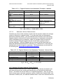
1
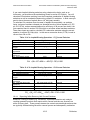
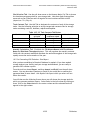
California Air Resources Board
Instructional Guidance for Mandatory GHG Emissions Reporting
December 2008
CHAPTER 10: PETROLEUM REFINERIES
(Guidance for Regulation Section 95113)
As listed in section 95113(a) of the regulation, the emissions data report for a
petroleum refinery must include the following information as applicable:
1. Stationary combustion CO2 emissions by fuel type
2. Stationary combustion CH4 and N2O emissions by fuel type
3. Consumption data for fuels and feedstocks
4. Hydrogen production plant emissions of CO2, CH4, and N2O
5. Specified process emissions
6. Specified fugitive emissions
7. Flaring emissions
8. Emissions from electricity generating units
9. Emissions from co-generation facilities
10. Indirect energy purchases
Calculation methods for each of these reporting requirements are discussed in this
chapter. Note that in addition to referring to the common methodologies section of
the regulation (section 95125), you will find general guidance on applicable methods
in Chapter 13 of this document. Information specific to refineries is included here.
10.1 Stationary Combustion Emissions
As indicated by the regulation’s general requirements (section 95103(a)(2)), the
operator needs to calculate and report emissions for each GHG separately for each
fuel type used (except where a CEMS is deployed, discussed below). Thus, in
compiling and reporting stationary combustion emissions you will be effectively
populating a matrix that looks something like the one below. The fuels you combust
may be different than those shown in the Table below, of course.
Table 10.1 Stationary Combustion GHG Emissions
Fuel
Refinery fuel gas
Natural Gas
Associated Gas
Diesel Fuel
Residual Fuel
Propane
CNG
Gasoline
Kerosene
Naphtha
CEMS (fuel mixtures)
CO2
CH4
N2O
n/a
n/a
The purpose of this chapter is to provide guidance on the requirements of section 95113 of the mandatory GHG reporting
regulation. As described more specifically in Chapter 1 of this document, this guidance does not add to, substitute for, or
amend the regulatory requirements as written in these or other sections of the regulation [Subchapter 10, Article 2,
sections 95100 to 95133, title 17, California Code of Regulations].
10-1
Refineries
California Air Resources Board
Instructional Guidance for Mandatory GHG Emissions Reporting
December 2008
10.1.1 Reporting Stationary Combustion CO2 emissions Using CEMS
In most cases CO2 emissions from stationary combustion will be calculated using
methods that are based on the type of fuel combusted. The one exception is when a
Continuous Emission Monitoring System (CEMS) is used to measure CO2 emissions.
CEMS may be used to measure and report stationary combustion emissions from single
or multiple combustion sources. New CEMS must be installed and operated according
to the requirements of 40 CFR Part 75, except that the ARB regulation does not trigger
a reporting requirement to the U.S. EPA. CO2 concentrations (rather than O2) and flue
gas flow measurements should be used to determine hourly CO2 mass emissions for any
new CEMS system, per section 95125(g)(7). Operators must also measure and report
fuel consumption that results in GHG emissions.
When you use a CEMS to determine GHG emissions resulting from the combustion of a
fossil fuel mixture, it will not be possible to separately report CO2 emissions for each
fuel contained in the mixture. The CEMS data are instead used to report CO2 emissions
from combustion of the mixture.
See the guidance for section 95125(g), found in section 13.7 of this document, for
additional direction on CEMS.
10.1.2 Options for Calculating and Reporting Refinery Fuel Gas CO2 Combustion
Emissions
For most California refineries, refinery fuel gas (RFG) represents a significant fraction
of the fuel that is combusted during refining processes. There also may be significant
compositional variation among multiple fuel gas systems within a refinery. It is
essential that fuel characteristics affecting GHG emissions be accurately determined.
The reporting regulation is designed to provide high resolution data to quantify CO2
emission from this very important source. Several quantification approaches are
available to provide operators with flexibility in exactly how to quantify refinery fuel
gas emissions, and these are discussed below. At most refineries, emissions must be
determined daily for each RFG system. In cases where multiple RFG systems are
mixed and homogenized prior to combustion, it may be more appropriate to determine
the carbon content of the mixture, rather than each system individually. The most
important consideration is to ensure that the carbon content of all RFG combusted is
accurately quantified.
There are three general procedural approaches for calculating CO2 emissions resulting
from the combustion of refinery fuel gas:
10.1.2.1 CEMS (section 95125(g)):
The operator may use a CEMS to quantify CO2 emissions from one or more refinery fuel
gas systems. Refer to section 95125(g) of the regulation and section 13.7 of this
guidance documentation for specifics concerning CEMS installation, operation and
emissions calculation.
10-2
Refineries
California Air Resources Board
Instructional Guidance for Mandatory GHG Emissions Reporting
December 2008
10.1.2.2 Carbon content testing using on-line instrumentation or discrete sample
laboratory analysis (section 95125(d)(3)(A)):
The operator may use on-line instrumentation (e.g., a gas chromatograph) to
determine fuel gas carbon content. An important consideration in evaluating any online compositional analysis method is that the instrumentation and analytical
methodology used provide a complete characterization of all major species present in
the refinery fuel gas system. In practice, the operator should ensure good quality data
is gathered on ≥95 percent of the mass of hydrocarbons present in each RFG system
where on-line instrumentation is used. ARB staff recommends that instrumentation be
operated, maintained, and calibrated according to original equipment manufacturer
(OEM) specifications, and located appropriately in order to obtain a representative
sample of the RFG system in question.
For each RFG system where on-line instrumentation is used, the operator must
determine carbon content and fuel molecular weight at least once every eight hours
that RFG from the system is combusted. Measurements should be taken at
approximately the same relative period (beginning, middle, or end) during each 8 hour
period--or at times during each 8 hour window appropriate to provide for
representative sampling.
For each analysis, the operator will also need to calculate refinery fuel gas molecular
weight (kg fuel/kg-mole) using the data from the on-line instrumentation.
To calculate daily CO2 emissions, the current day carbon content values (kg C/kg fuel)
should be averaged to calculate daily average carbon content. Similarly, the fuel
molecular weight determinations should be averaged. These daily average carbon
content and fuel molecular values are then applied to the equation found in section
95125(d)(3)(A) along with the amount of RFG combusted, to calculate daily CO 2
emissions. Daily emissions are then summed to calculate annual emissions from each
RFG system.
10.1.2.3 System specific CO2 emission factor (section 95125(e)):
This third approach requires you to use an on-line high heat value (HHV) analyzer.
HHV data and a daily carbon content determination are used to derive a daily refinery
fuel system specific CO2 emission factor. This emission factor is then used with a daily
average RFG system HHV value (from the on-line analyzer) to calculate CO2 emissions.
1.
Calculate a RFG system specific daily emissions factor: You need to determine
the carbon content and HHV for the RFG system in order to calculate a CO2
emission factor. To do this, once per day, determine the carbon content (kg
C/kg fuel), molecular weight (kg fuel/kg-mole) and the HHV (Btu/scf) of the
RFG system. Carbon content and fuel molecular weight are measured by
drawing a representative RFG sample and performing a carbon analysis.
Carbon content and molecular weight may also be determined using an on-line
instrument.
High heating value is determined either using data from the carbon analysis or
from an on-line HHV analyzer. When using data from an on-line HHV analyzer,
the operator uses either the hourly average HHV value coinciding with the hour
in which the carbon content determination is made, or the hour in which the
sample was collected for analysis. A daily emission factor (metric tonnes
10-3
Refineries
California Air Resources Board
Instructional Guidance for Mandatory GHG Emissions Reporting
December 2008
CO2/MMBtu) is then calculated using the equation found in section 95125(e)(3).
The operator should ensure that a representative sample is drawn for carbon
analysis, the HHV analyzer is properly installed in an appropriate location, the
carbon content analysis accurately characterizes the fuel, and sampling is
performed under conditions representative of prevailing operational
parameters.
2.
Calculate CO2 emissions: Once you have determined a daily CO2 EF for your
RFG system, daily CO2 emissions are calculated using the daily average RFG
HHV derived from the on-line continuous HHV analyzer. Use of a daily average
HHV is designed to integrate daily variations in RFG heating value (and
indirectly carbon content). This calculation is accomplished using the formula
found in section 95125(e)(4). RFG CO2 emissions for all RFG systems are then
summed to calculate facility RFG CO2 emissions.
Exception for Small Refineries. Refiners that qualify as “small” refiners under California
statutes may calculate CO2 emissions from refinery fuel gas combustion on a weekly basis,
rather than daily. See Title 13, California Code of Regulations, Section 22609(a)(32) to
determine whether your facility is “small.”
10.1.3 Calculating Natural Gas and Associated Gas CO2 Combustion Emissions (section
95125(c) or (d))
There are several steps required to calculate stationary combustion CO2 emissions
from natural gas and associated gas.
1. Determine fuel HHV – The operator needs to know the HHV of the natural gas
or associated gas in order to determine which method to use to calculate CO2
stationary emissions from these two fuels. HHV may be measured either by the
facility operator or by the fuel supplier. HHV may be determined by using the
ASTM methods listed in section 95125(c)(1)(B), or by using on-line
instrumentation.
2. Converting low heat value (LHV) to HHV - If you currently have installed an online analyzer that measures only LHV, you will need to convert LHV to HHV
using the approach shown in section 95125(c)(1)(C) where HHV = LHV x CF. If
the fuel in question is natural gas, you should use a conversion factor (CF) of
1.11. If the fuel is a mixture containing refinery fuel gas, simply derive a
weekly average fuel system specific CF where CF = HHV/LHV. The weekly HHV
may be derived from either from the daily HHV calculated as part of the daily
carbon content determination or from on-line instrumentation.
3. Next you will choose a CO2 emission calculation method based on fuel HHV
value. If the HHV of your natural gas, associated gas or mixture is ≥975 Btu/scf
but ≤1100 Btu/scf you should determine HHV on a monthly basis. The monthly
HHV value is then used with an EF (kg CO2/MMBtu) to calculate fuel CO2
emissions (section 95125(c)(1)). The applicable EF value can be found in Table
4 of regulation Appendix A. Choose the EF which corresponds to the correct
10-4
Refineries
California Air Resources Board
Instructional Guidance for Mandatory GHG Emissions Reporting
December 2008
HHV range of the natural gas or associated gas you combusted during the
month in question.
4. If the HHV of your fuel is either less than 975 Btu/scf or greater than 1100
Btu/scf either you or your fuel supplier must determine fuel carbon content a
minimum of once per month. CO2 emissions are then calculated using the
formula found in section 95125(d)(3).
10.1.4 Calculating CO2 combustion emissions from Fuel Mixtures (section 95125(f))
There are two critical requirements that must be met to ensure valid emissions
estimation whenever two or more fuels are mixed prior to combustion. First, the
amount of each fuel combusted must be determined accurately. Secondly, the fuel
combusted must be adequately characterized. Thus you must determine the
appropriate fuel characteristics (HHV and/or carbon content) of either the fuel
mixture or every individual fuel contained in the mixture.
The operator may choose to use a CEMS to determine fuel mixture CO2 emissions, in
which case fuel characterization is not required. The operator will still need to
measure consumption for each fuel, however.
If the operator mixes refinery fuel gas with natural gas or another fuel prior to
combustion, the resulting fuel mixture is subject to the more stringent refinery fuel
gas requirements concerning sampling frequency and emissions determination. In this
case section 95125(f) refers you to section 95125(d)(3)(A) or 95125(e).
10.1.5 Options for Calculating CO2 Combustion Emissions from Other Fuels (section
95125(a), (c), or (d))
The methods described in sections 95125(a), (c) and (d) of the regulation are applied
to the more common fuels, where composition, heating value, carbon content and
thus CO2 combustion emissions are well characterized and exhibit little variability. In
addition to CEMS (discussed above), the regulation provides three alternatives for
determining CO2 stationary combustion emissions for these fuels:
10.1.5.1 Default CO2 emission factor and default heat content (section 95125(a)):
Find the fuel in Table 4 of regulation Appendix A. Use the default HHV and CO2
emission factor values for the fuel along with fuel consumption data (mass or
volume/year) to calculate stationary combustion emissions for this fuel.
10.1.5.2 Measured HHV and default CO2 emission factors (section 95125(c)):
You may also choose to use measured (rather than a default value) HHV with a default
CO2 emission factor. If you choose to determine fuel HHV, you must comply with the
requirements of section 95125(c) and related sections dealing with parameters such as
sampling frequency and analysis methods.
10.1.5.3 Measured carbon content (section 95125(d)):
Finally, you may choose to measure fuel carbon content and calculate fuel stationary
combustion emissions using the appropriate solid, liquid, or gaseous fuel formula and
ASTM method found in section 95125(d). ARB staff recommends you choose an
10-5
Refineries
California Air Resources Board
Instructional Guidance for Mandatory GHG Emissions Reporting
December 2008
analytical method that provides data for ≥95 percent of the carbon in the fuel. For all
fuels other than refinery fuel gas, carbon content should be measured monthly.
Careful consideration of default values. In practice, when should you determine fuel HHV
and/or carbon content rather than use default values? If you have concerns or questions
concerning the accuracy of default values it would be appropriate to investigate in more
detail which approach is suitable to ensure an accurate accounting.
As an example, if you are using headspace gas as a fuel or feedstock and are presently
measuring only bulk liquid composition, you should examine the appropriateness of this
approach. How closely does the liquid analysis approximate the composition of the actual
fuel or feedstock, and is the measured HHV significantly different from the default value?
In this case, analysis of both phases should answer the question. When you are presented
with alternative approaches, choose the method that ensures the integrity of your emissions
report, not the simply the easiest or least expensive.
10.1.6 Calculating CO2 Combustion Emissions from Low Btu Gases (section
95113(a)(1)(E))
Section 95113(a)(1)(E) details stationary combustion CO2 emission calculations for low
Btu gases and flexigas. Pressure swing absorption off-gas, vapor recovery gases, and
asphalt tank headspace gases are examples of low Btu gases. If you have questions as
to whether a process gas that you generate might fall into this category, ARB
encourages you to discuss the issue with staff.
Flexigas is formed when hydrocarbons are thermally cracked in a flexicoker to produce
coke products. Usually low Btu gases are either used as a supplemental fuel that is
mixed with a fuel of higher Btu content and combusted as part of a fuel mixture, or
destroyed in a flare or other destruction device such as a thermal oxidizer.
Other than inclusion in CEMS estimates, low Btu gas stationary combustion CO2
emissions are determined depending upon their use:
10.1.6.1 Combustion of low Btu gases as a fuel:
If you are mixing a low Btu gas to supplement another fuel, consult sections
95125(f)(1)(A) and (C). If you are mixing a low Btu gas with refinery fuel gas, the
more stringent RFG requirements apply to the resulting mixture. If you mix a low Btu
gas with natural gas, the HHV of the resulting mixture determines which emissions
calculation method you should use, just as is the case with natural gas. If the HHV of
the natural gas/low Btu gas mixture falls in the 975 -1100 Btu range, then you should
determine mixture HHV monthly, use the appropriate default CO2 emission factor from
Table 4 of regulation Appendix A, and calculate emissions using the formula in section
95125(c). If the HHV of the mixture is above or below this range, you must measure
the carbon content of the mixture monthly and use the formula in section 95125(d)(3)
to calculate CO2 emissions.
10-6
Refineries
California Air Resources Board
Instructional Guidance for Mandatory GHG Emissions Reporting
December 2008
10.1.6.2 Destruction of low Btu gas in a flare or other destruction device (section
95113(d))
The operator should choose the appropriate emissions calculation method based on
the disposition of the low gas stream. Choose the applicable option below:
a) Your Low Btu gas is sent to a flare or flares and you report these flare
emissions to your local AQMD/APCD: In this case refer to section 95113(d)(2).
Choose the method you use based on your Air District reporting requirements.
For a more detailed discussion see the Flare/Control Device (section 95113(d)
discussion below.
b) Your Low Btu gas is destroyed in a destruction device such as a thermal
oxidizer and emissions are not reported to the local AQMD/APCD: In this case
refer to section 95113(d)(3). You must determine carbon content and
molecular weight of the low Btu gas quarterly and compute an annual average.
You must also determine the volume of low Btu gas destroyed annually (± 7.5
percent) and use the equation in section 95113(d)(3) to calculate annual CO 2
combustion emissions.
10.1.7 Calculating Stationary Combustion CH4 and N2O emissions (section 95125(b))
CH4 and N2O emissions resulting from fuel combustion represent a small fraction of
fuel combustion related GHG emissions. While CH4 and N2O emissions are strongly
dependent on combustion technology, calculation methods are fuel specific and based
on fuel HHV. You should choose the most appropriate of the following three methods
for calculating CH4 and N2O stationary combustion emissions.
10.1.7.1 Source Testing (section 95125(b)(4)):
The operator may elect to conduct source testing to determine fuel and combustion
specific emissions factors (EFs) for CH4 and/or N2O. The source test plan you use
must be approved by ARB and repeated at least annually under the supervision of ARB
or the local air district. EFs should be
expressed in terms of grams of CH4 or
Emission factors derived from source testing
are specific to fuel and combustion
grams of N2O per MMBtu. Additionally,
technology. If you conduct source testing on
the HHV of the fuel in question should be
a steam boiler combusting refinery fuel gas,
measured at the time of the source test.
for example, the derived CH4 and N2O EFs
Use the measured fuel HHV rather than a
should
be used only when calculating CH4 and
default value, and the methodology
N2O emissions from similar boilers combusting
specified in section 95125(b)(2). Source
refinery fuel gas.
testing is addressed in more detail in
Appendix B of this guidance document.
10.1.7.2 Measured HHV and a default emission factor:
Use the method found in section 95125(b)(2) in situations where the HHV of the fuel in
question is measured.
10.1.7.3 Default fuel HHV and emissions factors:
In the case where the fuel HHV is not measured, you may use default HHV and EF
values. Default HHV and EF values for CH4 and N2O are found in Table 4 of regulation
10-7
Refineries
California Air Resources Board
Instructional Guidance for Mandatory GHG Emissions Reporting
December 2008
Appendix A. For refinery fuel gas use the values listed for “still gas.” Use the
equation found in section 95125(b)(3).
10.1.8 Calculating CH4 and N2O combustion emissions from Derived Gases
The emission factors for derived gases, found in Table 6 of regulation Appendix A, are
applicable for species such flexigas, PSA off-gas, and low Btu gases in general.
10.2 Fuel and Feedstock Consumption
The operator is required to report both fuel and feedstock consumption as directed in
section 95113(a)(3). You should report in the units indicated the consumption of all
fuels combusted at the facility, and all feedstocks involved in processes that are used
to calculate GHG emissions. In addition, section 95103(a)(2) requires you to report
fuel consumption for each process unit or group of units where fuel use is separately
metered.
10.3 Reporting Hydrogen Production Plant Emissions
Refer to Chapter 11 of this document for guidance on reporting emissions from
hydrogen production facilities.
Hydrogen plants associated with petroleum refineries may be owned and operated by
the refinery, or by another entity contracted to provide hydrogen for the refinery.
Reporting responsibility rests on the entity with operational control of the hydrogen
plant, as discussed in Chapter 2.
10.4 Refinery Process Emissions
At most refineries the major source of process emissions of GHGs is catalyst
regeneration. Process emissions also are generated from process vents, asphalt
blowing, and sulfur recovery.
Using CEMS. Just as the processes that generate GHGs in a refinery differ, methods to
calculate GHG emissions are process specific. However, use of a CO2 CEMS to measure
process GHG emissions is an option. As is the case with CEMS used with stationary
combustion emissions, process CEMS must be installed and operated according to
requirements found in 40 CFR Part 75. (This does not mean you are required to report CEMS
CO2 emissions to U.S. EPA.)
10.4.1 Calculating CO2 Emissions from Catalyst Regeneration
Refinery catalyst may be regenerated in a number of different manners. The operator
should choose the most appropriate method in section 95113(b)(1) and (2), described
below, based on the manner in which catalyst is regenerated. Table 10.2 summarizes
the needed information.
10-8
Refineries
California Air Resources Board
Instructional Guidance for Mandatory GHG Emissions Reporting
December 2008
10.4.1.1 Reporting Fluid Catalytic Cracking Unit (FCCU) process CO2 emissions
(section 95113(b)(1)):
If you have a Fluid Catalytic Cracking Unit (FCCU), the GHG emissions quantification
method you will use is based on the calculation of hourly coke burn rate in the catalyst
regeneration unit. Here are the steps involved:
1. Coke burn rate is calculated on an hourly basis using the methodology specified
by the U.S. EPA in 40 CFR Part 63 (National Emission Standards for Hazardous
Air Pollutants: Petroleum Refineries). Coke burn rate input parameters are
derived from FCCU control room instrumentation. See the first equation in
95113(b)(A) for specifics. You should use the equation for the calculation of Qr
(the volumetric flow rate of exhaust gas before entering the emission control
system) which is provided in this section. Calculation of Qr is also based on 40
CFR Part 63 guidelines.
2. You will then calculate a daily average coke burn rate expressed in kg/day.
3. Next, you need to determine the carbon fraction in the coke burned. That is,
what fraction of the coke contained on spent catalyst is carbon? As an
example, if based on analysis of FCCU catalyst withdrawn from an appropriate
sampling location you determine that 95 percent of the mass on the spent
catalyst is carbon, carbon content would be expressed as CF = 0.95.
Assuring Carbon Fraction Accuracy. Note that the regulation does not specify a
frequency or methodology for the determination of the variable carbon fraction. As
FCCU CO2 emissions may represent a significant fraction of your refinery GHG
emissions, you will want to ensure that the methodology you use to determine your
spent and regenerated catalyst carbon fraction is accurate. ARB staff recommends
that you also examine the temporal variability of carbon fraction and choose an
analysis frequency that is appropriate. Some of the issues you should consider: at
what rate does the carbon fraction on spent and regenerated catalyst change; are the
changes linear; are there periodic operational changes (e.g. addition of new catalyst)
that may result in step changes in carbon fraction values; what changes in operating
conditions should trigger carbon fraction determination? It is recommended that you
develop a sound methodology and retain all data and experimental procedure
documentation. Some up-front sampling and/or data analysis will ensure that your
FCCU CO2 emissions are reported accurately, minimize lab and personnel costs, and
facilitate verification. Material balance based determinations of these variables may
be appropriate but this approach should be well documented and supported.
Calculate CO2 emissions from your FCCU using the equation found in section
95113(b)(1)(C) and shown below. See Table 10.4.1.1 for a description of the required
variables.
n
CO 2 = ∑ CR d ∗ CF ∗ 3.664 ∗ 0.001
1
10-9
Refineries
California Air Resources Board
Instructional Guidance for Mandatory GHG Emissions Reporting
December 2008
Table 10.4.1.1 FCCU CO2 Process Emissions
Required Data
n – number of days of
operation
CRd – daily average coke burn
rate
CF – carbon fraction in coke
burned
conversion factor – carbon to
carbon dioxide
Conversion factor kg to metric
tonnes
Units/Value
unitless
Data Source
Operator determined
kg/day
operator measured
unitless
operator determined
3.664
supplied
0.001
supplied
10.4.1.2 Calculating Other Catalyst Regeneration Process Emissions (section
95113(b)(2)):
Methods for GHG emissions determination for alternate catalyst regeneration
processes are presented in section 95113(b)(2) of the regulation and summarized
below.
a) Periodic Catalyst Regeneration Process Emissions. If you regenerate catalyst
periodically you should refer to the methodology found in section
95113(b)(2)(A). You will determine CO2 emissions occurring during each
regeneration cycle and sum to calculate annual emissions. In this case you will
need to know the mass of catalyst regenerated during each regeneration cycle.
You will also need to determine
The regulation allows you to use a default
the weight fraction of carbon on
value of zero for the weight fraction of
both the spent catalyst prior to
carbon on your regenerated catalyst. Keep
regeneration and on the
in mind that using this default value may
regenerated catalyst. As is the
result in an overestimation of your CO2
case with FCCU catalyst
emissions, and thus staff recommends that
regeneration, the regulation does
this variable be measured periodically
not specify an analytical
during the working lifetime of the catalyst.
methodology or measurement
frequency. Again, staff recommends that you choose an appropriate method
and sampling frequency to ensure that you accurately characterize emissions
from this source. The required variables and equation are found immediately
below.
10-10
Refineries
California Air Resources Board
Instructional Guidance for Mandatory GHG Emissions Reporting
December 2008
Table 10.4.1.2a Periodic Catalyst Regeneration CO2 Process Emissions
Required Data
n – number of days of
operation
CRR – mass of catalyst
regenerated
CFspent – weight fraction
carbon on spent catalyst
CFregen – weight fraction
carbon on regenerated
catalyst
Conversion factor – carbon to
carbon dioxide
Conversion factor – kg to
metric tonnes
Units/Value
unitless
Data Source
operator determined
kg/regeneration cycle
operator determined
unitless
operator determined
unitless (default = 0)
operator determined
3.664
supplied
0.001
supplied
CO 2 = ∑ CRR ∗ (CFspent − CFregen ) ∗ 3.664 ∗ 0.001
n
1
b) Reporting Continuous Catalyst Regeneration Process Emissions. If you
regenerate catalyst continually in an operation other than an FCCU you should
use the method found in section 95113(b)(2)(B). As is the case with periodic
catalyst regeneration discussed above, you need to determine carbon fraction
on both spent and regenerated catalyst. Choose an appropriate sampling
location, analytical methodology and sampling frequency. You will also need
to determine the average catalyst regeneration rate and the time the
regenerator was operational. These variables (shown in the Table below) are
entered into the equation found in section 95113(b)(2)(B) to calculate annual
CO2 emissions.
Table 10.4.1.2b Continuous Catalyst Regeneration - CO2 Process Emissions
Required Data
CCirc - average catalyst
regeneration rate
CFspent – weight fraction
carbon on spent catalyst
CFregen – weight fraction
carbon on regenerated
catalyst
H – hours regenerator
operated annually
Conversion factor – carbon to
carbon dioxide
Units/Value
tonnes/hr
Data Source
Operator determined
unitless
operator determined
unitless (default = 0)
operator determined
hours/year
operator determined
3.664
supplied
CO 2 = CCirc ∗ (CFspent − CFregen ) ∗ H ∗ 3.664
10-11
Refineries
California Air Resources Board
Instructional Guidance for Mandatory GHG Emissions Reporting
December 2008
10.4.2 Calculating Process Vent Emissions
If facility equipment continuously or periodically discharges a gas stream to the
atmosphere directly or after being routed to a control device and you do not report
these process vent emissions elsewhere in your GHG report (e.g. flare or other control
device emissions, refinery fuel gas combustion, etc), you must report CO2, CH4 and N2O
emissions from process vents. It is important to avoid double counting of process vent
emissions. Additionally, if you transfer a process vent stream to a third-party facility
for processing, the responsibility for reporting resulting emissions is also transferred to
that third-party facility.
To quantify process vent emissions you need to measure the vent release rate and
duration of venting to determine the volume of gas emitted. You must also measure
the molar fraction of each GHG (CO2, CH4, and N2O) in the vent gas stream.
Especially in the case of hydrogen plant process vent emissions, measurement of flow
rate and gas composition is difficult at best. ARB staff recommends that you consult
AQMD/APCD regulations for additional guidance. For example, South Coast Air Quality
Management District Rule 1189 – Emissions from Hydrogen Plant Process Vents,
provides valuable direction for sampling and analyzing these process vent streams.
Table 10.4.2 Process Vent Emissions - CO2, CH4, and N2O
Required Data
VR – vent rate
Fx – molar fraction of X in
vent gas stream (X = CO2,
CH4, or N2O)
MWx – molecular weight of X
MVC – molar volume
conversion
VT – time duration of venting
n – number of ventings
CF – kg to metric tonnes
Units/Value
scf/unit time
kg/kg-mole
choose MVC for 20°C or 60°F
time
number
0.001
Data Source
operator measured
supplied
supplied
operator determined
operator determined
supplied
n
E x = ∑ VR ∗ Fx ∗ MW x ÷ MVC ∗ VT ∗ 0.001
1
10.4.3
Calculating Asphalt Production Emissions
If you conduct asphalt blowing operations at your facility you are required to report
CO2 and CH4 emissions that result from control measures. The assumption is that
emissions from asphalt blowing operations are directed to a destruction device such as
a flare or incinerator for control.
It is important not to double count these emissions. If asphalt plant blowing emissions
are sent to a flare and you report emissions from this flare to your local AQMD/APCD
you will report GHG emissions using the methodology in regulation section 95113(d), as
discussed in section 10.6.1 of this chapter. They would not be calculated using the
following methodology.
10-12
Refineries
California Air Resources Board
Instructional Guidance for Mandatory GHG Emissions Reporting
December 2008
If you control asphalt blowing emissions using a destruction device such as an
incinerator, you should use the methodology found in section 95113(b)(4). You will
calculate CH4 emissions resulting from the incomplete combustion of asphalt blowing
emissions as well as combustion/destruction related CO2 emissions. In both cases you
need to know the mass of asphalt blown (103 bbl/year) annually.
To calculate CH4 emissions from the mass of asphalt blown annually, an emission
factor (volume of methane released per thousand barrels of blown asphalt) of 2,555
scf CH4/103 bbl, and an assumed destruction efficiency of 98 percent are used in the
first equation found in section 95113(b)(4)(A) to calculate annual methane emissions.
These same inputs are used to calculate CO2 combustion emissions using the second
equation in section 95113(b)(4)(A). In this case a conversion factor (2.743) is used to
convert from CH4 to CO2.
Table 10.4.3a Asphalt Blowing Operations - CO2 Process Emissions
Required Data
MA – mass of asphalt blown
EF – methane emissions
MWCH4 – methane molecular
weight
MVC – molar volume
conversion
DE – methane destruction
efficiency
CF – kg to metric tonnes
Units/Value
103 bbl/yr
2,555 scf CH4/103 bbl
16.04 kg/kg-mole
Data Source
operator measured
supplied
supplied
choose MVC for 20°C or 60°F
supplied
98% (expressed as 0.98)
supplied
0.001
supplied
CH4 = (M A ∗ EF ∗ MWCH4 ÷ MVC)(1 − DE ) ∗ 0.001
Table 10.4.3b Asphalt Blowing Operations - CH4 Process Emissions
Required Data
MA – mass of asphalt blown
EF – methane emissions
MWCH4 – methane molecular
weight
MVC – molar volume
conversion
DE – methane destruction
efficiency
CF – CH4 to CO2
CF – kg to metric tonnes
Units/Value
103 bbl/yr
2,555 scf CH4/103 bbl
16.04 kg/kg-mole
Data Source
operator measured
supplied
supplied
choose MVC for 20°C or 60°F
supplied
98% (expressed as 0.98)
supplied
2.743
0.001
supplied
supplied
CO 2 = (M A ∗ EF ∗ MWCH4 ÷ MVC) ∗ DE ∗ 2.743 ∗ 0.001
10.4.4
Reporting Sulfur Recovery Unit Process Emissions
Numerous refining processes (e.g. distillation, hydrodesulfurization and catalytic
cracking) generate products that require sulfur removal and thus are directed to a
sulfur recovery plant. These process streams also contain entrained hydrocarbons that
are typically oxidized during the sulfur removal process and subsequently emitted as
10-13
Refineries
California Air Resources Board
Instructional Guidance for Mandatory GHG Emissions Reporting
December 2008
CO2. This section of the regulation (section 95113(b)(5)) is designed to account for
these emissions.
To calculate CO2 emissions from a sulfur recovery plant you need to know the volume
of gas treated annually at your plant. Depending upon the pumping configuration of
your sulfur recovery plant, this may require measurement of multiple input stream
flows. Make sure that you account for all sour gas streams entering the plant. A
default molecular fraction (%) of CO2 in the sour gas treated of 20 percent (expressed
as 0.20), may be used to then calculate CO2 emissions as shown in section
95113(b)(5)(A).
If you believe that this default value may overestimate or underestimate CO2
emissions, you may submit a request to ARB to conduct source testing for one or more
of the sour gas streams entering your sulfur plant. For example, if you have one sour
gas stream that has a low carbon content, you may submit a source test plan for that
gas stream to ARB for review. If ARB approves your source test plan you will conduct
source testing annually, during a period of typical and representative operating
conditions and under the supervision of ARB or local AQMD/APCD personnel. For all
sour gas streams that you do not source test, you should use the default value of 20
percent. In the case where you do conduct source testing, CO2 emissions for the
source tested sour gas stream should be summed with CO2 emissions from all nonsource tested streams and total CO2 emissions related to sulfur recovery reported.
Table 10.4.4 Sulfur Recovery Units - CO2 Process Emissions
Required Data
FR – volumetric flow of acid
gas to SRU
MWCO2
MVC – molar volume
conversion
MF – molecular of CO2 in sour
gas
0.001
Units/Value
metric tonnes/yr
Data Source
operator measured
44 kg/kg-mole
choose MVC for 20°C or 60°F
supplied
supplied
default MF = 20% or
operator source test
CF – kg to metric tonnes
supplied or operator source
test derived
supplied
CO 2 = FR ∗ MWCO2 ÷ MVC ∗ MF ∗ 0.001
10.5 Reporting Fugitive Emissions
The reporting regulation requires that the operator report four categories of fugitive
emissions –- methane and nitrous oxide from wastewater treatment, methane from oilwater separators, methane from storage tanks, and methane from fugitive equipment.
Each of these is discussed below.
10.5.1 Reporting Wastewater Treatment Fugitive Emissions
Both methane and nitrous oxide may be emitted during the treatment of refinery
wastewater. Microbial production of methane occurs under anoxic conditions and a
small fraction of nitrous oxide, an intermediate product in the nitrification/
denitrification cycle, is emitted to the atmosphere.
10-14
Refineries
California Air Resources Board
Instructional Guidance for Mandatory GHG Emissions Reporting
December 2008
10.5.1.1 Wastewater Methane Emissions
Before you sample your wastewater streams, the operator should consult Table 12 in
Appendix A of the regulation. Based on the specifics of wastewater treatment and
discharge at your facility (first two columns of Table 12) you will need to select a
methane correction factor (MCF) which is simply the fraction of waste that is treated
anaerobically at the facility in question. The Table contains default MCF values both
for untreated discharge and six general aerobic and anaerobic treatment situations.
Note that methane recovery for anaerobic treatment is not considered here.
Therefore if have an enclosed anaerobic treatment facility where methane is captured
and not emitted to the atmosphere, you would not be required to report methane
emissions here.
There are only two characterization categories provided for aerobic treatment
facilities -- a well managed system where small amounts of methane may be emitted
and an overloaded and not well-managed system. A range of MCF values is listed for
these two treatment conditions, 0 – 0.4. If you choose to characterize your treatment
facility as well maintained with no significant methane emissions and use a MCF value
of zero, you would not be required to report emissions.
Once you have evaluated your treatment and chosen an appropriate MCF value, to
determine wastewater related emissions you will need to know the volume of
wastewater that is discharged annually to your treatment facilities.
To calculate methane emissions you will also need to determine the chemical
oxidation demand (COD – kg/m3) of the wastewater and any of any sludge that is
removed from the treatment facility. You should sample and measure wastewater
COD on a quarterly basis. Choose an appropriate sampling location where a
representative sample of incoming wastewater composition can be collected, and
sample when situations are representative of normal operational conditions. The
regulation does not specify a specific method for the determination of wastewater
COD. The determination of COD is a common practice. ARBstaff suggests you consult a
recognized reference source such as:
Standard Methods for Examination of Water and Wastewater, 20th edition
Available at: http://www.standardmethods.org/
If you have more than one wastewater treatment facility you will need to determine
the COD of wastewater entering each system. The following variables are then used
to calculate methane emissions: annual wastewater volume treated, average COD,
sludge COD removed, methane generation capacity (0.25 kg CH4/kg COD) and MCF
from Table 12.
10-15
Refineries
California Air Resources Board
Instructional Guidance for Mandatory GHG Emissions Reporting
December 2008
Table 10.5.1.1 Fugitive Emissions from Wastewater Treatment - Methane
Required Data
Q - Volume of wastewater
treated
CODqave – average of quarterly
COD
S – COD removed in sludge
B – methane generation
capacity
MCF – methane conversion
factor
Conversion factor – kg to
metric tonnes
Units/Value
m3/yr
Data Source
operator measured
kg/m3
operator measured
kg COD/yr
0.25 kg CH4/kg COD
operator measured
supplied
unit-less
0.001
operator determined from
Table 12, regulation
Appendix A
supplied
CH4 = [(Q ∗ COD qave ) − S]∗ B ∗ MCF ∗ 0.001
10.5.1.2
Wastewater Nitrous Oxide emissions:
Calculation of nitrous oxide emissions requires that the operator measure the nitrogen
content of effluent on a quarterly basis. If you have more than one autonomous
wastewater treatment facility, you must determine N2O emissions from each facility.
Samples should be collected at a location representative of wastewater entering the
facility immediately prior to treatment. Again, the regulation does not specify a
method of analysis and staff suggests that you consult with a reference text or
contract laboratory. ARB staff suggests that you consult the EPA Clean Water Act
Analytical Methods documentation for references (e.g. Method 351.2) concerning the
determination of total nitrogen in wastewater. This documentation can be found at
the following link: www.epa.gov/waterscience/methods/.
Table 10.5.1.2 Fugitive Emissions from Wastewater Treatment - Nitrous Oxide
Required Data
Q - Volume of wastewater treated
N in effluent
N2O emission factor
CF – kg N2O-N to kg N2O
CF – kg to metric tonnes
Units/Value
m3/yr
kg N/m3 - annual
average
0.005 kg N2O-N/kg N
1.571
0.001
Data Source
operator measured
operator measured - quarterly
supplied
supplied
supplied
N2 O = Q ∗ Nqave ∗ EFN2O ∗ 1.571∗ 0.001
10.5.2 Reporting Oil-Water Separator Fugitive Emissions
Fugitive methane emissions from oil/water separators must also be calculated if you
have these devices at your facility and emissions are not diverted to a destruction
device. You should first consult Table 13 in regulation Appendix A. Here you will see
that for three types of oil/water separators, gravity, dissolved air flotation (DAF), and
induced air flotation (IAF), the methane emission factor is zero when these devices are
10-16
Refineries
California Air Resources Board
Instructional Guidance for Mandatory GHG Emissions Reporting
December 2008
connected to a functioning destruction device. If this is the case at your facility, you
are not required to report GHG emissions here. The destruction of low Btu gases such
as those recovered from an oil/water separator are covered in section 95113(d)(3).
Table 13 does provide methane emission factors for gravity, DAF and IAF oil/water
separators when they are either covered or uncovered, and not connected to a
destruction device. In these cases you will report methane emissions using the
method in this section. You need to know the volume of water annually treated by
the separator. The volume of treated water is used along with the appropriate
oil/water separator EF from Table 13 to calculate methane emissions. A conversion
factor of 0.6 is used to convert from nonmethane hydrocarbons to methane.
Table 10.5.2 Fugitive Emissions from Oil/water Separators - Methane
Required Data
EFsep - NMHC emission factor
Vwater – volume of water
treated annually
CFNMHC – NMHC to CH4
conversion factor
Conversion factor – kg to
metric tonnes
Units/Value
kg NMHC/m3
m3/year
Data Source
operator determined from
Table 13, regulation
Appendix A
operator measured
unit-less – 0.6
supplied
0.001
supplied
CH4 = EFsep ∗ Vwater ∗ CFNMHC ∗ 0.001
10.5.3 Reporting Storage Tanks Fugitive Emissions
There are three types of emissions from hydrocarbon storage tanks: working losses,
breathing losses and flashing losses. Working losses occur as a result of the filling and
emptying processes. Internal headspace gas is expelled and external air is pulled into
a storage tank as product enters and exits the tank. Breathing losses as a result of
changes in environmental parameters, such as solar and thermal heating and cooling,
cause changes in internal liquid and vapor volumes. Ambient winds can also cause
tank breathing emissions as they pass the tank exterior. Flashing losses occur when
liquid introduced into a tank changes pressure and volatiles contained in the liquid
“flash” off.
Fugitive tank emissions will be determined using the U.S. EPA TANKS model.1 This
model calculates working and breathing VOC emissions. Model generated VOC outputs
will converted to methane emissions using a default conversion factor of 0.6 (CH4 = 0.6
* VOC). Alternatively, you may use the results of storage tank headspace analysis to
1
Note that this program was developed by the American Petroleum Institute (API). API retains
the copyright and has granted permission for the nonexclusive, noncommercial distribution of
this material to governmental and regulatory agencies. TANKS is available for public use but
cannot be sold without written permission from API, the U.S. EPA, Midwest Research Institute,
and The Pechan-Avanti Group.
10-17
Refineries
California Air Resources Board
Instructional Guidance for Mandatory GHG Emissions Reporting
December 2008
determine a tank specific conversion factor, but it is suggested that you consult ARB
staff prior to using this option.
The TANKS model is used to calculate VOC emissions from above-ground storage tanks
containing crude oil, asphalt, naphtha, and distillate oils. If any of these storage tanks
are equipped with vapor recovery technology, vapors are actively collected and
emissions are accounted for elsewhere (e.g., flare GHG or refinery fuel gas system
reporting), to avoid double-counting you should not report them here.
There are several steps required to generate an emission report for your storage tanks:
1. Install TANKS on a suitable computer;
2. Set up a chemical database for crude oil, asphalt, naphtha, and distillate
components;
3. Establish your storage tank database;
4. Generate emissions reports for each storage tank;
5. Sum storage tank VOC emissions;
6. Convert VOC emissions to methane emissions using the default factor (0.6).
10.5.3.1
Installing TANKS
TANKS is a window based program available at no cost from the US EPA at the
following location. The model can be downloaded from
www.epa.gov/ttn/chief/software/tanks/index.html. Consult the system requirements
link to ensure that the computer on which you plan to install TANKS meets the
minimum requirements (operating system, RAM, hard disk space).
A user’s manual is available at the following web page.
User’s manual: www.epa.gov/ttn/chief/software/tanks/tanks409b/tank4man.pdf
While the user manual is 1999 vintage it remains a very useful document.
A list of Frequent Asked Questions (FAQ) can be found here:
FAQ: www.epa.gov/ttn/chief/faq/tanksfaq.html#1
Another EPA document you may find very helpful is the September 2006 report
entitled “Emission Factor Documentation for AP-42, Section 7.1, Organic Liquid
Storage Tanks. This report contains a detailed description of the types of storage
tanks, perimeter seals, and deck fittings. It is available here:
www.epa.gov/ttn/chief/ap42/ch07/bgdocs/b07s01.pdf
Another resource is the Santa Barbara County Air Pollution Control District Rule 325,
Crude Oil Production and Separation, found at
www.arb.ca.gov/DRDB/SB/CURHTML/R325.PDF.
Read the Installation Instructions file first and then install TANKS 4.09D on your
computer. You will need to uninstall previous versions of TANKS. If you have previous
databases you can import them into TANKS 4.09D. See sections 3.4 Using a Previous
Database and 6.0 Database Utilities of the Users Manual for instructions.
10-18
Refineries
California Air Resources Board
10.5.3.2
Instructional Guidance for Mandatory GHG Emissions Reporting
December 2008
Establishing your Chemical Databases
The first step in the set-up procedure of the TANKS model should be to establish
chemical databases for the types of hydrocarbons for which you will be calculating
VOC emissions – crude oil, asphalt, distillates, and naphtha.
1. Crude Oil - the model contains one Chemical Database for crude oil with an
RVP of 5. Use this database for your crude oil storage tanks.
2. Distillate oils – in this case you also use the default database contained in the
TANKS model.
3. Naphtha – TANKS contains a data base for jet naphtha – use this database.
4. Asphalt – in the case of asphalt products will need to establish a Chemical
Database for this petrochemical.
To establish a chemical database for asphalt storage tanks:
Run TANKS
You will first see a screen containing the USEPA Emissions Factor and Inventory Group
logo, click in this box or wait approximately five seconds and the screen will advance
and display the TANKS Model Notice Box describing the model origin and distribution
restrictions. Click OK to advance to the following screen.
10-19
Refineries
California Air Resources Board
Instructional Guidance for Mandatory GHG Emissions Reporting
December 2008
Close the Welcome screen by clicking the cancel option.
Next click the Data button on the top menu bar, choose Chemical from the drop-down
menu, and then move the cursor to the right to select Edit Database. See the panel
below.
TANKS will display an established Chemical Database sheet (acetaldehyde). Click the
Add New button at the bottom left of this database to display a blank Chemical
Database sheet. Fill in this sheet as shown below:
10-20
Refineries
California Air Resources Board
Instructional Guidance for Mandatory GHG Emissions Reporting
December 2008
When you have entered all the data for the Asphalt Chemical Database Save this file.
You are now ready to establish your storage tank data base.
10.5.3.3
Establishing your storage tank data base
The next step in working with TANKS is to enter descriptive information concerning
the storage tank or tanks for which you will be modeling VOC emissions.
If you are creating a new tank file, make sure that the Create New Tank Record button
is selected, highlight the type of tank, and click the OK button. Make sure that you
have selected the correct tank type from the five tank type options list:
Horizontal Fixed Roof Tank:
Vertical Fixed Roof Tank:
Internal Floating Roof Tank:
External Floating Roof Tank:
Domed External Floating Roof Tank:
HFRT
VFRT
IFRT
EFRT
DEFRT
10-21
Refineries
California Air Resources Board
Instructional Guidance for Mandatory GHG Emissions Reporting
December 2008
You will then see the following window:
Across the top of this screen you will see five tabs: Identification, Physical
Characteristics, Site Selection, Tank Contents, and Monthly Calculations. Step through
the first three tabs to determine what information you will need to enter. These first
three tabs and data requirements for each are discussed briefly below. Consult the
User’s Guide for a more detailed discussion.
Identification Tab. The Identification Tab is the same for all types of storage tanks.
Identification Tab: enter data for each of the five fields on this page.
Identification No:
Description:
State:
City:
give each tank a unique ID name. This will be the name
that TANKS assigns to this Tank Record. Thus it must be
unique and you should maintain a master list to aid in
identification when you edit each tank profile and
generate your emissions report.
enter a brief description of each tank. This will provide
you with additional information to aid in tank
identification.
select California from the pull down menu accessed by
clicking on the down arrow
select the nearest city to the location of the tank. Note
that for both Los Angeles and San Francisco, there are
two choices, denoted by the suffixes AP and C.O. AP is
airport and C.O. is “City Of”.
10-22
Refineries
California Air Resources Board
Instructional Guidance for Mandatory GHG Emissions Reporting
December 2008
If you wish to review or edit an existing storage tank record select Open an Existing
Tank Record, highlighting the tank record you wish to edit, and clicking OK.
Physical Characteristics Tab. The data you will enter differs depending upon the
type of storage tank record that you are establishing. Below are screen shots for the
Physical Characteristics data requirements for each of the five tank types.
10-23
Refineries
California Air Resources Board
Instructional Guidance for Mandatory GHG Emissions Reporting
December 2008
Section 4.0 of the User’s Guide, Entering Tank Data, steps through the data entry
process for each of the tank types.
Note that in the case of a VFRT where the tank is heated, when you enter data on the
Tank Contents tab you are required to enter the Average, Maximum and Minimum
Liquid Surface Temperature and the Bulk Liquid Temperature.
10-24
Refineries
California Air Resources Board
Instructional Guidance for Mandatory GHG Emissions Reporting
December 2008
Site Selection Tab. Use the pull-down menu on the Nearest Major City Tab to choose
the location most appropriate for your storage tank. Note that major metropolitan
areas such as San Francisco and Los Angeles list two locations suffixed with AP
(airport) or C.O. (City of).
Tank Contents Tab. Use this Tab to designate the contents of each of the storage
tanks. Use the following selection to set up storage tank contents files for storage
tanks containing crude oil, distillate, asphalt and naphtha.
Table 10.5.3.3 Tank Contents Tab Entries
Tank Contents
Crude oil
Asphalt
Distillate oil
Chemical Category
of Liquid
Crude oil
Petroleum Distillates
Petroleum Distillates
Single or Multicomponent Liquid
single
single
single
Naphtha
Petroleum Distillates
single
Chemical Name
Crude oil (RVP 5)
Asphalt
Distillate Fuel oil no.
2
Jet Naphtha (JP4)
Monthly Calculations Tab. Click both the Fill Mixture Names with First Mixture
Name and Distribute Throughput buttons. This will populate the monthly contents
fields with the contents name and distribute the annual throughput of the storage tank
equally across the twelve months of the year.
10.5.3.4 Generating VOC Emissions – Run Report
After you have established a Chemical Database for asphalt (if you have asphalt
storage tanks at your facility) and your storage tank database, you are ready to
generate VOC emission reports.
From the tool bar choose Report, and then Annual, and Brief from the pull down
menus. You may also select Summary or Detail if you would like to examine the
generated data in more detail – this depth of the report which you select will not
affect the results.
You will then see the following Screen where you will choose the storage tanks for
which you generate emission reports. Select tanks in the left column by clicking on
them, click on the Select button in the center column and the selected tank will
appear in the right column.
10-25
Refineries
California Air Resources Board
Instructional Guidance for Mandatory GHG Emissions Reporting
December 2008
When you have chosen all the storage tanks for which you want to generate emissions
reports, click Run Report.
The output of the report is then used to calculate methane emissions. Use the Total
VOC emissions (TANKS output expressed in lbs VOC) to calculate methane emissions.
Multiply this number by either the default conversion factor of 0.6 or the tank specific
conversion factor derived from tank headspace analysis to calculate annual methane
emissions. Finally, convert from pounds of methane to metric tonnes methane and
report this value.
You should frequently back-up your TANKS data bases to ensure that all your dataentry work is protected from unforeseen computer problems such as a hard-disk
failure.
10.5.4 Reporting Equipment Fugitive Emission - Methane
Equipment fugitive methane emissions methods are based upon your local AQMD/APCD
Leak Detection and Repair (LDAR) procedures. You will need to extend your LDAR
monitoring to all gas service components. This includes all components carrying
natural gas, refinery fuel gas, and low Btu gases. All components should be identified
as one the following six classification types: value, pump seal, connector, flange,
open-ended pipe, and other. For guidance you should consult and use the Component
Identification and Counting Methodology found in the following CAPCOA (1999)
document:
California Implementation Guidelines for Estimating Mass Emissions of Fugitive
Hydrocarbon Leaks at Petroleum Facilities, CAPCOA and CARB, 1999.
www.arb.ca.gov/fugitive/fugitive.htm
10-26
Refineries
California Air Resources Board
Instructional Guidance for Mandatory GHG Emissions Reporting
December 2008
All gas service components should be screened using a monitoring instrument capable
of detecting methane. Screenings should be conducted at the frequency interval
required by your local air district. Specific screening procedures and instrument
calibration requirements can be found in EPA Reference Method 21 published in 40 CFR
60, Appendix A (EPA Method 21), www.epa.gov/ttn/emc/promgate/m-21.pdf.
First identify and screen your gas service components. Component screening values
will be used to calculate methane emissions. The CAPCOA document referenced above
provides several methods by which VOC emissions may be calculated using component
screening values. You will use Method 3: the Correlation Equation Method with
modifications as required by the procedures that your local AQMD/APCD has put in
place. You will calculate VOC emissions for three categories of components based on
the component screening value:
1. Zero components – where the screening value, corrected for background is
indistinguishable from zero.
2. Leaking components – components with screening values greater than zero but
less than the screening value limit above which the local AQMD/APCD does not
allow the use of correlation equations for the calculation of VOC emissions.
This upper bound screening value is either 9,999 ppmv or 99,999 ppmv.
3. Pegged components with SVs above the upper SV/correlation equation limit.
Each of these three calculation methods is discussed in more detail below:
For each of the six Component Types you will find a Default Zero Factor (ZFi0 in kg/hr)
in Table 14 of regulation Appendix A. VOC emissions for all zero components are then
calculated and summed using the equation found in section 95113(c)(4)(A)(3)(a).
Table 10.5.4a Fugitive Equipment VOC Emissions - Zero Components
Required Data
CCi – number of i components
where SV=0
ZFi0 – zero VOC emission
factor for component i
t = time from last screening
Units/Value
number
Data Source
operator determined
kg VOC/hour
column two - Table 14,
regulation Appendix A
Operator determined
time - hours
i = component type, where 1 = valve, 2 = pump seal, 3 = others, 4 = connector, 5 =
flange, and 6 = open-ended line
6
E VOC−0 = ∑ CC i ∗ ZFi0 ∗ t
i=1
For all leaking components where the component screening value is above zero and
below the limit set by your local air district above which correlation equations may
not be used for VOC calculation (either 9,999 or 999,999 ppmv) use the equation found
in section 95113(c)(4)(A)(3)(b).
10-27
Refineries
California Air Resources Board
Instructional Guidance for Mandatory GHG Emissions Reporting
December 2008
Table 10.5.4b Fugitive Equipment VOC Emissions - Leaking Components (SV > 0 and
less than upper bound for use of correlation equation)
Required Data
σi - correlation equation
coefficient for component i
SVn – component screening
value for component n
βi – correlation equation
exponent for component type
i
t = time from last screening
Units/Value
unitless
Data Source
column three - Table 14,
regulation Appendix A
operator determined
ppmv
unitless
column three - Table 14,
regulation Appendix A
time - hours
operator determined
If your local air district has set a screening value limit of 9,999 ppmv for the use of
correlation equations (SV > 9,999 ppmv is considered pegged) you will use the
equation found in section 95113(c)(4)(A)(c) to calculate VOC emissions.
6
E VOCL −C = ∑
i=1
∑ (σ
n
n =1
i
)
∗ SVnβi ∗ t
Table 10.5.4c Fugitive Equipment VOC Emissions - Pegged Components
(SV > 9,999 ppmv)
Required Data
CCi – number of i components
where SV> 9,999 ppmv
PFiP-10 – VOC emission factor
for component type i pegged
over 9,999 ppmv
t – time since last screening
Units/Value
number
Data Source
operator determined
kg VOC/hour
column four, Table 14,
regulation Appendix A
hours
operator determined
6
E VOCP−10 = ∑ CC i ∗ PFiP−10 ∗ t
i=1
If your local air district has set a screening value limit of 99,999 ppmv for the use of
correlation equations (SV > 99,999 ppmv is considered pegged) you will use the
equation found in section 95113(c)(4)(A)(d) to calculate VOC emissions.
Table 10.5.4d Fugitive Equipment VOC Emissions - Pegged Components
(SV > 99,999 ppmv)
Required Data
CCi – number of i components
where SV> 99,999 ppmv
PFiP-100 – VOC emission factor
for component type i pegged
over 99,999 ppmv
t – time since last screening
Units/Value
number
Data Source
operator determined
kg VOC/hour
column five, Table 14,
regulation Appendix A
hours
10-28
operator determined
Refineries
California Air Resources Board
Instructional Guidance for Mandatory GHG Emissions Reporting
December 2008
6
E VOCP −100 = ∑ CC i ∗ PFiP −100 ∗ t
i=1
After you have calculated VOC emissions for all your zero components, leaking
components and pegged components, sum the three to obtain your fugitive equipment
VOC emissions. The sum total of VOC emissions is then multiplied by CF, a VOC to CH4
conversion factor and a kg to metric tonnes conversion factor (0.001) to calculate
total methane emissions.
n
CH4 = ∑ (E VOC−0 + E VOC−LC + [E VOCP −10 Lor LE VOCP −100 ]) ⋅ CFVOC ∗ 0.001
1
In most cases you should be able to determine a system specific VOC to methane
conversion factor (CF) based on determinations of gas composition and methane
content from fuel analysis. In cases where fuel analysis data is available, use the mass
CH4/mass fuel ratio to calculate a system specific CF. In cases where representative
data is not available you should use a default CF value of 0.6.
10.6
Reporting Emissions from Flares and Other Control Devices section 95113(d)
Regulatory methods for the calculation of flaring emissions are based on the reporting
requirements of your local air district.
You should make sure that stationary combustion emissions of CO2, CH4, and N2O are
reported for all flare pilot and purge gas consumed in the flaring process. Consult the
previous discussion of stationary combustion emissions for details.
10.6.1 Reporting Flare Emissions
Next, based on local air district reporting requirements, the operator will report
emissions resulting from the flaring of hydrocarbons routed to your flares.
If you are required to report flaring CH4 and NMHC emissions to your local air district
(e.g. BAAQMD, Regulation 12, Rule 11) you will report CO2 and CH4 flaring emissions as
shown in section 95113(d)(2).
First, calculate CO2 emissions resulting from the combustion of both NMHC species and
methane contained in hydrocarbon streams routed to flares for destruction. Use the
formula found in section 95113(d)(2)(A). The method assumes a carbon fraction of 0.6
for the NMHC species. You should use the flaring destruction efficiency specified by
your local air district.
10-29
Refineries
California Air Resources Board
Instructional Guidance for Mandatory GHG Emissions Reporting
December 2008
Table 10.6.1a Flaring Emissions – CO2 and CH4 (Using NMHC and CH4)
Required Data
CFNMHC – NMHC carbon fraction
NMHC – flare NMHC emissions
Units/Value
unitless CFNMHC = 0.6
kg/day
CH4 - flare emissions
kg/day
FE – flare destruction
efficiency
CF – methane to carbon
dioxide
CF – kg to metric tonnes
CF – carbon to carbon dioxide
percent
Data Source
supplied
operator determined – as per
air district reporting
requirements
operator determined – as per
air district reporting
requirements
specified by local air district
2.743
supplied
0.001
3.664
supplied
supplied
365
CO 2 = ∑ [CFNMHC ∗ NMHC ∗ FE ÷ (100 − FE ) ∗ 3.664 + CH 4 ∗ FE ÷ (100 − FE ) ∗ 2.743 ] ∗ 0.001
1
If you are subject to SCAQMD Rule 1118, Control of Emissions from Refinery Flares, you
should calculate ROG as specified in Attachment B of Rule 1118 and report flare CO2
emissions as shown in section 95113(d)(2)(B). This document is available at the
following link: www.aqmd.gov/rules/reg/reg11/r1118.pdf.
The method assumes an ROG carbon fraction of 0.6, and you should use the flare
destruction efficiency specified by your local air district.
Table 10.6.1b Flaring Emissions – CO2 and CH4 (using ROG)
Required Data
CFROG – ROG carbon fraction
ROG – flare ROG emissions
FE – flare destruction
efficiency
CF – kg to metric tonnes
CF – carbon to carbon dioxide
Units/Value
unitless CFROG = 0.6
kg/day
percent
0.001
3.664
Data Source
supplied
operator determined – as per
air district reporting
requirements
specified by local air district
supplied
supplied
365
CO 2 = ∑ (CFROG ∗ [ROG ∗ FE ÷ (100 − FE )] ∗ 3.664 ∗ 0.001)
1
Finally if you are not currently required to report flaring emissions to your local air
district, you will use a simplified calculation method based on refinery feed throughput. The only variable you will need to supply is refinery through-put in m3/year.
10-30
Refineries
California Air Resources Board
Instructional Guidance for Mandatory GHG Emissions Reporting
December 2008
Table 10.6.1c Flaring Emissions – CO2 (using refinery through-put)
Required Data
RFT – refinery through-put
EFNMHC – NMHC emission factor
CFNMHC - NMHC to carbon
conversion factor
CF – carbon to CO2
CF – kg to metric tonnes
Units/Value
m3/year
0.002 kg NMHC/m3
unitless 0.6
3.664
0.001
Data Source
operator determined
supplied
supplied
supplied
supplied
CO 2 = RFT ∗ EFNMHC ∗ CFNMHC ∗ 3.664 ∗ 0.001
10.6.2 Reporting Emissions from Destruction Devices Other than Flares
This last section of the refining reporting section of the regulation (section 95113)
addresses the destruction of hydrocarbons streams, including but not limited to coker
flue gas, vapor recovery gases, casing, PSA off-gas and process vent gases. These
gases may be destroyed in an incinerator or thermal destruction device, or combusted
as a supplemental fuel in heaters, boilers etc. If you use a CO boiler to dispose of
hazardous waste, these emissions should be reported here. You should report the
resultant CO2 emissions using the method in section 95113(d)(3) if these emissions are
not reported elsewhere, such as part of your flaring or stationary combustion
emissions.
In this case you will need to analyze these gas streams on a quarterly basis –
determining both carbon content and molecular weight. You will also need to
determine the volume of each gas stream with an accuracy of at least ± 7.5 percent.
You should choose analytical methods that provide an accurate measurement of the
carbon content of these gas streams. Your choice of analytical methods should be
based on the characteristics of the individual gas streams and may be different for
different gas streams. CO2 emissions should be calculated for all gas streams
destroyed.
Table 10.6.2 Emissions from other Control Devices
Required Data
GVA – volume of gas A
destroyed
CCA – carbon content of gas A
MWA – molecular weight of gas
A
MVC – molar volume
conversion
CF – carbon to carbon dioxide
CF – kg to metric tonnes
Units/Value
scf/year
Data Source
operator determined
kg C/kg fuel – annual average
of quarterly determinations
kg/kg-mole – annual average
of quarterly determinations
choose MVC for 20°C or 60°F
operator determined
supplied
3.664
0.001
supplied
supplied
operator determined
CO 2 = GVA ∗ CC A ∗ MW A ∗ 1 ÷ MVC ∗ 3.664 ∗ 0.001
10-31
Refineries
California Air Resources Board
Instructional Guidance for Mandatory GHG Emissions Reporting
December 2008
10.7 Reporting Requirements for Electricity Generation and Cogeneration
If electricity generation or cogeneration occurs at your facility (within the same
contiguous boundary and under your operational control), emissions from these
activities must be included in your emissions data report. If the electricity generating
or cogeneration facility has a nameplate generating capacity of 1 MW or more, and its
CO2 emissions from electricity generating
activities trigger the separate reporting
Do you have electricity generation or a
threshold of 2,500 metric tonnes, the
cogeneration system on site?
report must comply with the
If your system is at least 1 MW and
requirements of regulation sections
emitted at least 2.500 MT CO2 from
95111 and 95112, as applicable.
electricity
generation, refer to the
Regulation section 95111 includes the
methods provided for the electricity
electricity generating facility reporting
generation and cogeneration sectors to
requirements and is described in Chapter
calculate GHG emissions from these
8 of this document, while section 95112
sources. See Chapters 8 and 9.
provides the cogeneration system
requirements and is covered in Chapter 9. Refer to those sections of the regulation
and the associated guidance chapters for more information.
If your electricity generating activities are not large enough to trigger these additional
reporting requirements, include these emissions in your facility GHG report as
additional stationary sources, with emissions calculated specific to fuel type like your
other sources.
The regulation also includes definitions for “cogeneration facility,” “cogeneration
system,” “generating facility,” “generating unit,” and “electricity generating
facility,” which may be helpful in evaluating whether these types of activities or units
are at the facility.
10.8 Reporting Indirect Energy Usage
If you purchase and consume electricity from a retail provider or a facility that you do
not own or operate, you need to report the amount of electricity usage and identify
the provider. Similarly, if you purchase and consume steam, heat, and/or cooling
from a facility you do not own or operate, you need to report this thermal energy use
and identify the provider. The methodologies are found in Chapter 13.
10-32
Refineries