1
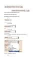
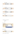
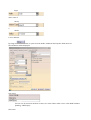
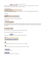
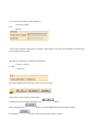
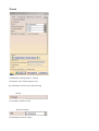
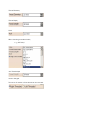
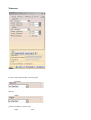
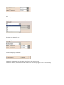
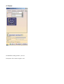
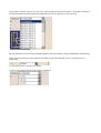
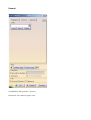
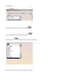
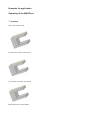
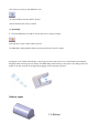
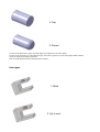
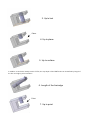
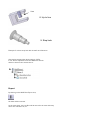
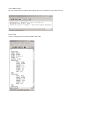
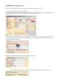
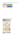
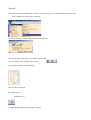
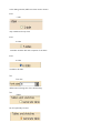
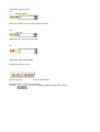
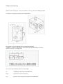
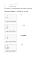
MWF-Bore 2004 / MWF-Drafting 2004
The User Manual
of the
Plug-ins for CATIA V5
Engineering for the world of tomorrow.
Preface
The years of experience within several construction areas,
like mold making, tool manufacture, plant construction and product development,
has induced us to develop individual software applications for our customers.
Resulting from the special needs of interaction between construction and manufacturing, the feature-based
MW-F B o r e had been developed in close cooperation with the car industry. The cooperation ensures that
the planning, the construction and the manufacturing implementation are congruent. By means of the MWFBore hole generator, the design engineer is able to insert features, like sink holes, threads, ejector holes,
tempered holes, hydraulic holes, fits, or pillar guides, in the CATIA model.
By means of the MW-F D r a f t i n g drawing module, you are able to create documented drawing
derivations of your constructions within a few minutes.
Many advantages result from it:
--- The dimensioning of the holes becomes unnecessary.
--- Thus, an almost resp. completely paperless manufacturing will be ensured.
--- The smooth information and process chain guarantees high process security.
--- The manual value input in the NC becomes unnecessary.
--- A time saving of up to 70 % can be reached.
--- Numbering of the holes in the individual views (optionally 1/5 or 6 sides).
--- Representation of the coordinate axes.
--- Optional creation of hole tables.
--- Any MWF info, like name, position, tolerance and threads, can be shown
in the hole table.
Contents
The MWF-Bore dialog window
1. Hole
2. Thread
3. Tolerance
4. Groove
5. General
Examples for application
Operating of the MWF-Bore
Bottom types
1. V-Bottom
2. Flat
3. Round
Hole types
1. Hole – Blind
2. Hole – Up to next
3. Hole – Up to last
4. Hole – Up to plane
5. Hole – Up to surface
6. Hole – Length of line/edge
7. Up to point
8. Up to line
9. Step hole
Export
The MWF-Bore register card
The MWF-Drafting dialog window
General
Tables and sketches
Theoretical representation
of the bottom and hole types
The MWF-Bore dialog window
Hole
The MWF-Bore dialog window \ Hole
Description of the Hole register card
The first figure behind the hole definition describes the current step, and the second figure defines the total
number of the steps.
Example picture:
1st step of altogether 3.
The five register cards which define the hole.
Description of the Hole register card.
By activating the box in front of the lettering
Chamfer,
it is possible to define
Chamfer width
and
Chamfer angle
of the chamfer.
In case of a step hole, regarding the hole type, you have to define
a diameter,
a kind of hole (e. g Blind )
as well as regarding the selection
Blind
where you have to define
a Depth.
When choosing a different kind of hole,
e. g., Up to next
Up to last
or
Length of line / edge
or
Min sink depth,
it is possible to define an additional value for
Offset
The Offset value will be added at the end of the hole.
When choosing
Up to plane
or
Up to surface
or
Up to point
or
Up to line,
you have to mark a
Limit.
The Bottom can be chosen as
V-Bottom,
Flat
and
Round
When choosing
V-Bottom,
you have to define a value for
Angle
and in case of
Round,
a
Radius
is to be defined.
By using the
button to open the hole details, additional hole-specific fields and new
functionalities will be displayed.
Hole name
The hole can be named as desired. In future, the name will be taken over in other MWF-modules
(Drafting, CAM Export).
Hole index
Value for index
makes it possible to allocate a version
number to the hole according to which can be later scanned.
Incremental depth
When choosing the option, the values for the step depth are not absolutely displayed any longer but
incrementally created and edited.
Total depth
The total depth is important for the design engineer.
Variable steps
If the currently displayed step is defined as being variable, the total depth of the hole will remain constant in
case of further hole changes while the step defined as being variable will be automatically varied lengthwise
as required.
By activating the checkbox, this function can be switched off again.
All hole-specific values will be saved in the CATIA part.
By using tbe
button, the hole details will be closed.
By clicking on this arrow, the next step of a hole can be edited.
By clicking on this arrow, the previous step of a hole can be edited.
deletes the current step
inserts a new hole step after the shown one
The Direction of the hole will be defined by
Normal to surface
and
Reverse
If none of the options is selected, for example, a body edge or also a line can be defined as direction by
activating the grey text field.
Whether the respective hole step is described by
a Groove /Thread
or/and
a Tolerance,
this will be displayed in the above picture by an active box.
If the hole is created with all of its steps,
it will be filed in CATIA after clicking on the
When clicking on the
By using the
button.
button, the whole MWF dialog window will be closed.
button, a preview of the hole can be created.
Thread
The MWF-Bore dialog window \ Thread
Description of the Thread register card
By activating the box in front of the lettering
Thread,
it is possible to define for the
Type No standard
the following numerical values:
Thread Diameter,
Thread Depth,
Pitch.
When choosing a standard value,
e. .g. MF 4x0,5
the Thread depth
can be changed.
The sense of rotation of the thread can be reversed.
Tolerance
The MWF-Bore dialog window \ Tolerance
In case of No standard input, concerning the
Diameter
and the
Depth,
you have to define a value for the
upper
and
lower tolerance
The
Diameter
of a Tolerance can be chosen from predefined values, if necessary.
The tolerance values for the
Depth,
must be always input manually.
Concerning Incremental, the tolerance only refers to the current step.
Concerning Absolute, the tolerance refers to the sum of the step lengths up to the current step.
4. Groove
The MWF-Bore dialog window \ Groove
Description of the Groove register card
It is possible to define a groove for every step. After having activated the checkbox, a proposal according to
the DIN Standards will be automatically displayed based on the diameter of the hole step.
All DIN Standards can be found in the MWF database and maintained by using the MWF-Bore Administrator.
When choosing a value from the database according to the DIN Standards, only the n measurement is
changeable,
i. e. the groove can be moved in the depth.
In case of No standard selection, all values are arbitrary.
General
The MWF-Bore dialog window \ General
Description of the General register card
With regard to
General
already existing holes can be opened by using
resp. newly-drawn holes can be saved by using
By means of the
command, holes can be removed again.
In the select box , the saved resp. loaded holes are listed.
Examples for application
Operating of the MWF-Bore
1st possibility
Fist a hole surface resp.
a surface and a hole central point
or a surface and a line are chosen
which had been created before.
After that, by clicking on the MWF-Bore icon,
the hole definition window will be opened
and the desired hole can be created.
2nd possibility
2. First the MWF-Bore icon will be chosen (the icon is turning orange)
and only then, a hole surface will be chosen.
The MWF-Bore dialog window will be opened and the hole can be created.
Analogous to the CATIA functionality, a temporary preview of the hole to be created will be immediately
displayed while entering the hole data in the MWF dialog. Alternatively to the input in the dialog mask, the
depth of the last step can be changed by dragging at this temporary element.
Bottom types
1. V-Bottom
2. Flat
3. Round
In case of the flat bottom type, the step depth corresponds to the hole depth.
In case of the V-bottom or round bottom type, the bottom geometry of the step depth will be added.
If only an edge derounding is planned,
hole and step depth will close with the plane surface.
Hole types
1. Blind
2. Up to next
3. Up to last
Plane
4. Up to plane
5. Up to surface
In addition to the limits usually used in CATIA, the step depth of the MWF holes can be defined by length of
the line and edges, points and lines.
6. Length of the line/edge
Point
7. Up to point
Line
8. Up to line
9. Step hole
Example for a three-step hole with chamfer and V-bottom.
After having stopped the desired hole in CATIA,
it can also be repositioned via the MWF-Bore sketch
which is shown in the structural tree.
Export
By clicking on the MWF-Bore Export icon,
the data will be scanned. .
At the same time, two new files will be stored in the same directory
where the CATIAPart is, too.
In the MWFLog file,
the not-scanned holes will be listed which do not correspond to the Tebis format
The TFF file
is the exchange format between MWF and Tebis.
The MWF-Bore register card
Under Tools > Options > Infrastructure, there is now a MWF-Bore register card.
Here the user must enter the desired options.
Via the CATIA administration functionality, default values can be already entered by the administrator. The
administrator can decide if the user is allowed to overwrite the entries.
In case of an activated license server, the host name of the license server and the TCP / IP port of the
communication must be entered. View and MWF-Bore are alternatively selectable. In addition, drafting
license is optionally possible.
Enter the correct login data for the access to the database server.
You can choose between two scanning formats (Tebis version 1.1 and Tebis version 2.0).
It is possible to choose own color settings for tolerance, depth, and thread.
The MWF-Drafting dialog window
General
After having created the MWF holes in CATIA, you can change to the CATIA drafting environment via
Start > Mechanical construction > Drafting.
The CATIA drawing creation dialog window will be opened.
After having selected a layout and confirmed it by using
you can change to the drafting environment.
By marking the frame of a 2D drawing,
this one will be selected.
By clicking on the
Moldware icon,
the MWF-Drafting dialog window will be opened.
In the dialog window, different views can be chosen.
View
1 side
only considers the top view.
View
5 sides
considers all sides with the exception of the back.
View
6 sides
considers all sides.
The
Font size
defines the lettering size of the 2D drawing.
The
Tables
can be optionally created
by activating the checkbox.
The
Decimal places
define the number of the decimal places in the table.
The
Font size
defines the size of the font in the table.
The
Scale
defines the scale of the drawing.
Possible input values >0 to 1.
By clicking on the
button, both sketches
and tables will be created when activating.
By using
, you can close again the MWF-Drafting dialog window.
Tables and sketches
Apart from the axes (here: -x and +x as well as -y and +y), the new drawing includes
a complete topological numbering of the MWF holes.
The position of the numberings can be changed by dragging.
In addition, a separate table with an appropriate theoretical drawing of the hole
will be created for every MWF hole.
You can read the following values from this table:
no.:
topological numbering of the MWF hole
name:
original name of the CATIA hole
x,y,z:
position of the starting central point of the MWF hole
D1:
diameter of the 1st step
L1:
length of the 1st step
Thread and tolerances are considered within the respective D or L field of the step.
Theoretical representation of the bottom and hole types
1. V-bottom
2. Flat
3. Rounded
-
4. Round
Thread
D1: 44 x 1.25
i. e. diameter of the
first step = 44
with a pitch of 1.25
L1: 20 / 25
i. e. thread depth = 20
core hole depth = 25
Step hole with tolerance n of the second step
D2: 40 H7
i. e. diameter of the second step = 40 with an ISO tolerance H7
Important: the drawing can be saved at any place. However, it is not allowed to
move the original part of which the drawing had been created!