1
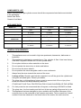
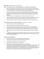
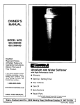
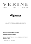
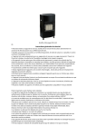
THE
'THURCROFT'
MOBILE GAS STOVE
MODEL NUMBER’S FFSC00MB / MB1 / MB2
USE ONLY IN A WELL VENTILATED
AREA
INSTALLATION, USER AND SERVICING INSTRUCTIONS
THESE INSTRUCTIONS MUST REMAIN WITH THE USER
THIS APPLIANCE HAS BEEN FITTED WITH A SUITABLE REGULATOR AND HOSE. THE REGULATOR
WILL FIT A CYLINDER WITH A 21mm VALVE.
THIS APPLIANCE REQUIRES A 7 kg. CYLINDER OF GAS.
This appliance must not be used in high rise apartments, basements, bathrooms
or bedrooms.
When you first light your stove you may detect a slight odour. This will disappear after a few hours use.
0087
THIS APPLIANCE MEETS THE REQUIREMENTS OF THE EUROPEAN GAS DIRECTIVE
1
Contents
Page No.
List of components
3
Appliance Data
3
GENERAL REQUIREMENTS
3
Ventilation
4
Preparing the appliance for use
4
USERS GUIDE
6
Lighting the stove
6
Moving your stove
7
Cleaning and storage
7
SERVICING & MAINTENANCE
Installation & Service Record
7
10
Important Note
These Installation Instructions must
be adhered to without exception.
2
COMPONENTS LIST
Before connecting the gas cylinder ensure that all the components listed below are included
in the packaging;
Mobile Gas Stove
Ceramic Coal Matrix
APPLIANCE DATA
MODEL No.
FFSC00MB
FFSC00MB1
FFSC00MB2
GAS TYPE
G30
G30
G30 or G31
JET SIZE
0.75mm
0.75mm
0.75mm
HEAT INPUT (Gross)
2.42 kW
2.42 kW
2.42 kW
REGULATOR OUTLET
PRESSURE
28-30mbar
28-30 or 37mbar
30mbar
CYLINDER SIZE
7 Kg
7 Kg
7 Kg
DIMENSIONS
H : 700mm W : 400mm
H : 700mm W : 400mm
H : 700mm W : 400mm
D :450mm
D :450mm
D :450mm
GENERAL REQUIREMENTS
1
This appliance must not be used in high rise apartments, basements, bathrooms or
bedrooms.
2
This appliance is designed to operate from a 7 kg. cylinder of Gas. It has been factory
fitted with a regulator suitable for a 21mm cylinder valve.
3
Do not place clothes or other materials on the stove.
4
Do not operate the stove close to chairs and fabrics.
5
Do not move the stove when lit.
6
Do not position the stove alongside a wall or near curtains etc.
7
Always face the stove towards the centre of the room.
8
Leakage of Gas: Should a gas leak be suspected, turn off the gas at the cylinder and
extinguish all naked lights. Contact your dealer.
9
The glass door on this appliance forms a guard to prevent risk of fire or injury from
burns and it should not be permanently removed.
IT DOES NOT GIVE FULL PROTECTION FOR YOUNG CHILDREN OR THE INFIRM.
10
For their protection we recommend that a fireguard, conforming to BS 8423 be fitted.
11
The glass door, the front casting and the front of the top casting all become hot in use.
12
This appliance has been designed to give a realistic coal fire effect. Because of this
soot may form on the underside of the ceramic coal matrix. This is normal but, if small
nodules of soot are observed in the flame holes of the matrix, the matrix must be
3
removed from the appliance when it is cool and gently brushed clean. This type of soot
formation only occurs after a long period of burning at low fire.
Ventilation
Use only in a well ventilated room.
1
The room in which the heater is to be used must be provided with adequate
ventilation at all times to ensure the proper removal of products of combustion
and to reduce the possibility of condensation. The smallest sized room in which
the appliance should be operated is 48m³ for a living room and 24m³ for other
rooms except for basements, bathrooms and bedrooms where the appliance
must not be used. A permanent vent with an effective area of 62cm2 is required
together with a window that can be opened.
Preparing the appliance for use
1
Fitting the Ceramic Coal Matrix
Loosen the slotted headed screw from beneath the glass door. Lift the door upwards
and remove. (The top of the door is located with a hidden screw in a keyhole and the
door may have to be moved around to free it from the front casting).
Warning: The Ceramic Coal Matrix is very fragile.
2
Carefully remove the packaging from above the ceramic. The front of the ceramic coal
matrix is lower than the back. Place the ceramic on its mounting ledges above the
burner. Refit the glass door and tighten the securing screw.
Gas Connection
Shroud
Cylinder
Front view of the stove showing the
glass door and the ceramic coal
matrix
4
3
Fitting the Gas Cylinder
Warning: Gas cylinders must not be fitted or changed in the presence of naked
flames.
4
Remove the plastic safety cap by rotating it until the arrow points out through the gap
in the cylinder shroud, pull on the plastic strap and then lift off the safety cap.
5
Remove the rear access door and place the cylinder close behind the stove. Rotate the
cylinder so that the gap in the shroud points in the direction of the stove. Make sure the
regulator switch is in the 'OFF' position before trying to mount the regulator on to the
cylinder. Taking care not to twist the hose, mount the regulator onto the cylinder valve
and push down until there is an audible click. Lift and rotate the cylinder and place it
inside the stove.
6
To remove the regulator from the cylinder first turn the stove off by turning the switch
downwards and then press the switch inwards towards the body of the regulator. Lift to
release from the cylinder
Note: The regulator supplied with your stove may have been exchanged for the factory
fitted item and may mount in a different manner to the above. Refer to the regulator
instructions supplied with your appliance.
7
Replace the rear access door and secure with its latch.
8
Examine the flexible tubing between the regulator and the gas control regularly and if
worn or perished get your dealer to fit a new piece.
9
New hose must be to B.S.3212 Type 2 fitted with suitable hose clips, length 330mm.
10
Any replacement regulator must be to B.S.3096 set at 28mbar (11.2 in w.g.).
Please read the note at the end of the ‘Lighting the Stove’ section about lighting the
stove for the first time after changing the gas cylinder.
Rear view of stove showing the
gas cylinder, the rear door and
the top cover
The Thurcroft stove
ready for use
5
VERTICAL / ON
HORIZONTAL / OFF
Regulator
USERS GUIDE
Lighting the stove
1
Reach through the aperture in the rear access door and turn on the gas by turning the
switch on the regulator upwards.
2
Depress the control knob and turn it fully clockwise. Keep the control knob fully
depressed and rotate it fully anticlockwise. This will operate the spark generator (you
will hear a ‘click’) and allow gas to flow to the burners. The pilot burner and the main
burner should light. If they do not ignite repeat the operation. Check that the pilot
burner has lit (it can be viewed, or its reflection can, by looking at the lower right hand
side of the glass door.) If the stove is new or has not been used for some time the main
burner will light before the pilot burner. In this case the pilot burner may not light from
the main burner and the knob will have to be released and the burners relit.
3
Once the burners are both alight hold the control knob down for a further 15 seconds
and then release. The burners should stay alight. If they do not, repeat the lighting
procedure only holding the knob down for longer.
4
Once the burner is alight the control knob can be turned further anticlockwise to go to
the high fire setting and clockwise to low fire. If the stove does not light on the second
try, wait three minutes before attempting to light the appliance again. This is to allow
any gas vented in the first two attempts time to disperse.
5
To turn the appliance OFF, reach through the aperture in the rear access door and turn
off the gas at the bottle by turning the switch on the regulator downwards to a
horizontal position.
LOW FIRE
HIGH FIRE
The Control Knob
6
Note; After changing the cylinder more than one attempt may be needed to light
the appliance as air may have entered the pilot gas supply and this will take a
few attempts to pass through. This may also happen if the stove has not been
used for some time and may also cause the pilot to burn with a roaring noise.
The pilot should burn quietly after a few minutes. Sometimes the stove may not
light at all after being fitted with a new gas cylinder. This is caused by the
remaining residue of the incombustible gas used to purge the cylinder during
the re-filling process. In this case the control knob may have to be held down for
several minutes to allow this gas to pass out of the cylinder. Whilst holding the
knob down make frequent attempts to light the stove to avoid a flare up when
the burner does light.
Moving your stove
Warning: Do not attempt to move the stove while it is burning or even while it is still
hot.
1
Wait until the stove is cold before moving. It is easier to move with rear door and gas
cylinder removed. If the stove is to be transported by motor vehicle the gas cylinder
should be removed as should the Ceramic Coal Matrix which should be carefully
packed to avoid breakage.
Cleaning and storage
1
Do not attempt to clean the stove unless it is cold. It should only require occasional
dusting or a wipe with a damp cloth. If the stove is not to be used for some time, cover
and store in a dust free place.
Servicing
This appliance MUST be serviced by a registered engineer annually,
And MUST include changing the oxy-pilot.
AFTER REPLACING ANY GAS FITTING, CHECK FOR GAS TIGHTNESS.
WARNING
This product may use fuel effect pieces containing Refractory Ceramic Fibre
(RCF). This material contains man-made vitreous silicate fibres along with
fibrous glass and mineral wool. Excessive exposure to these materials may
cause temporary irritation to eyes, skin and respiratory tract; consequently, it
makes sense to take care when handling these articles to ensure that the release
of dust is kept to a minimum.
The appliance should be serviced at least once a year by a registered engineer.
This is the basic procedure.
7
Basic Service (See Figures 1 and 2, page 9)
Note: The oxy pilot must be changed annually as a condition of the guarantee.
1
Remove the glass door panel and the ceramic coal matrix as previously described.
2
Clean any debris and soot from the burner top. This can be done by using a soft brush
or a vacuum cleaner. The burner mesh should be thoroughly cleaned.
3
The ceramic coal matrix can be cleaned by gently brushing with a soft brush in a
direction away from the person and any persons nearby. This operation should be
performed outside facing downwind. A vacuum cleaner must not be used for this
purpose.
4
Check that there is no impairment to the electrode spark or pilot burner.
5
Check that the pilot flame is satisfactory. If this is not the case remove and clean (see
instructions below). If the flame is still unsatisfactory replace the pilot burner.
6
Replace the burner ceramic and glass door panel and secure with the fixing screw.
To Remove the Burner/ Control Assembly (See Figures 1 – 6, page 9)
1
Remove the rear access door and the cylinder.
2
Remove the glass door panel and the ceramic coal matrix.
3
Pull off the control knob. Unscrew the control lock nut (use 17mm box spanner).
4
Undo and remove the two screws inside the cylinder space. These two screws are
situated either side of the appliance between the bolts securing the front casting.
5
Gently pull the control valve clear of the top casting and the lift the whole assembly
clear.
6
To replace, follow the reverse of the above locating the control valve in the top casting
first. Check for gas leaks. Make sure that the spark lead is secured so that it cannot
trail under the gas cylinder.
To Remove the Pilot Burner
1
Remove the Burner/ Control assembly as described above.
2
Unscrew the thermocouple nut from below the control valve.
3
Unscrew the pilot supply tube from the pilot burner.
4
Gently pull the spark lead from the electrode.
5
Remove the two screws holding the pilot burner to its bracket.
Note; Apart from cleaning the pilot burner cannot be serviced and must be replaced as
a complete unit if faulty. When replacing, carefully coil the excess length of the
thermocouple just under the control valve and push out of the way of the cylinder when
the burner/ control assembly is re-installed into the stove body. Make sure that the
spark lead is secured so that it cannot trail under the gas cylinder.
8
To Remove the Injector
1
Remove the Burner/ Control assembly as described above.
2
Unscrew the tube nut securing the gas supply pipe to the injector elbow.
3
Unscrew the injector elbow from its carriage.
4
The injector can now be removed from the elbow.
To Remove the Control Valve
1
Remove the Burner/ Control assembly as described above.
2
Gently pull the spark lead from the electrode on the pilot burner.
3
Unscrew the thermocouple, the two 8mm supply tubes and the 4mm pilot supply tube.
4
Remove the control valve.
FIGURE 2
FIGURE 1
FIGURE 4
FIGURE 3
9
Installation & Service Record
Please ensure that installer completes the installation record below
INSTALLATION RECORD
Appliance Supplied by: JJJJJJJJJ.J..JJ....
Installation Date: JJJJJSerial No.: JJJ...JJ...
Installed By: JJJJ..J... No.: J..JJJJJ
Signed by Installer: JJJJJJJJJJJJJJ..J
10
st
nd
RECORD OF 1 SERVICE
RECORD OF 2
SERVICE
Serviced by: JJJJ No.:JJJJ....
Serviced by: JJJJ No.:JJJJ....
Service Date: JJJJJ Signed: J.JJ.J...
Service Date: JJJJJ Signed: J.JJ.J...
Comments: JJJJJJJJJJJJJJJJJ
Comments: JJJJJJJJJJJJJJJJJ
JJJJJJJJJJJJJJJJJJJJJJJ JJJJJJJJJJJJJJJJJJJJJJJJ
JJJJJJJJJJJJJJJJJJJJJJJ JJJJJJJJJJJJJJJJJJJJ..JJJ
rd
th
RECORD OF 3 SERVICE
RECORD OF 4 SERVICE
Serviced by: JJJJ No.:JJJJ....
Serviced by: JJJJ No.:JJJJ....
Service Date: JJJJJ Signed: J.JJ.J...
Service Date: JJJJJ Signed: J.JJ.J...
Comments: JJJJJJJJJJJJJJJJJ
Comments: JJJJJJJJJJJJJJJJJ
JJJJJJJJJJJJJJJJJJJJJJJ JJJJJJJJJJJJJJJJJJJJJJJJ
JJJJJJJJJJJJJJJJJJJJJJ.
JJJJJJJJJJJJJJJJJJJJJJJ..
RECORD OF 5th SERVICE
RECORD OF 6th SERVICE
Serviced by: JJJJ No.:JJJJ....
Serviced by: JJJJ No.:JJJJ....
Service Date: JJJJJ Signed: J.JJ.J...
Service Date: JJJJJ Signed: J.JJ.J...
Comments: JJJJJJJJJJJJJJJJJ
Comments: JJJJJJJJJJJJJJJJJ
JJJJJJJJJJJJJJJJJJJJJJJ JJJJJJJJJJJJJJJJJJJJJJJJ
JJJJJJJJJJJJJJJJJJJJJJJ JJJJJJJJJJJJJJJJJJJJJJJ
th
th
RECORD OF 7 SERVICE
RECORD OF 8 SERVICE
Serviced by: JJJJ No.:JJJJ....
Serviced by: JJJJ No.:JJJJ....
Service Date: JJJJJ Signed: J.JJ.J...
Service Date: JJJJJ Signed: J.JJ.J...
Comments: JJJJJJJJJJJJJJJJJ
Comments: JJJJJJJJJJJJJJJJJ
JJJJJJJJJJJJJJJJJJJJJJJ JJJJJJJJJJJJJJJJJJJJJJJJ
JJJJJJJJJJJJJJJJJJJJJJJ JJJJJJJJJJJJJJJJJJJJJJJ..
th
th
RECORD OF 9 SERVICE
RECORD OF 10 SERVICE
Serviced by: JJJJ No.:JJJJ....
Serviced by: JJJJ No.:JJJJ....
Service Date: JJJJJ Signed: J.JJ.J...
Service Date: JJJJJ Signed: J.JJ.J...
Comments: JJJJJJJJJJJJJJJJJ
Comments: JJJJJJJJJJJJJJJJJ
JJJJJJJJJJJJJJJJJJJJJJJ JJJJJJJJJJJJJJJJJJJJJJJJ
JJJJJJJJJJJJJJJJJJJJJJ.. JJJJJJJJJJJJJJJJJJJJJJJ..
11
B-123340
Issue 1
BFM Europe Limited
Trentham Lakes
Stoke on Trent, Staffordshire ST4 4TJ
Tel: (01782) 339000 Fax: (01782) 339009
Email: [email protected]
www.bfm-europe.com
12