1
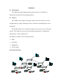
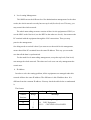
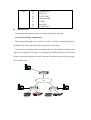
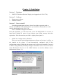
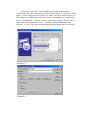
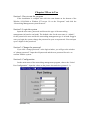
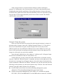
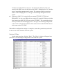
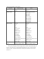
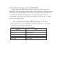
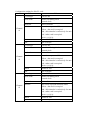
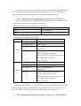
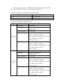
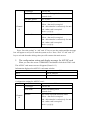
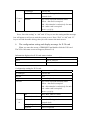
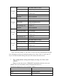
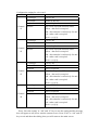
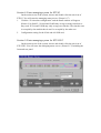
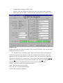
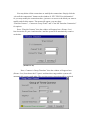
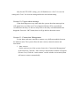
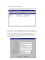
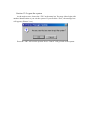
Networking Management system Protocol
User’s Manual
Content
Introduce
Chapter 1: Installation
Section 1: Hardware
Section 2: Software
Section 3: How to install
Chapter 2: How to start the system
Section 1: Starting the system
Section 2: Login the system
Section 3: Change the password
Section 4: Configuration
1. COM port configuration
2. Edit the polling time
Section 5: Enter the system
Section 6: Diary
Section 7: Enter managing system for ERM-MUX
1. The configuration setting and display message for E1 card
2. The configuration setting and display message for Sub-E1 card
3. The configuration setting and display message for N*64K card
4. The configuration setting and display message for 64K/128K card
5. The configuration setting and display message for ASYNC card
6. The configuration setting and display message for X.50 card
7. The configuration setting and display message for Voice
(FXSO)card
8. The configuration setting and display message for Voice
(E&M)card
Section 8 : Enter managing system for ETU03
Section 9 : Enter managing system for ETU-DXC
Section 10: Urgent alarm message
Section 11: Connection Management
Section 12: Operator Management
Section 13: Logout the system
Introduce
Environment
The NMP (Networking Management system Protocol) is available for
Windows95/98/2000/NT4.0 operating platform.
Features
This NMP uses the graph-icon display, enables the network users to set the
configurations by simply clicking the mouse, instead of remembering the varied
commands.
This NMP contains a lot of functions, high-security system, easy to learn and
operate. This NMP also specialize in the trapping management, Configuration
management, security management.
The NMP is available for the following models :
NMC
ETU-DXC
ERM-MUX
ETU03-MUX
Structuring drawing
网管计算机
S
y
i
W
A
l
g
n
o
C
a
L
c
r
L
r
o
k
o
m
s
o
o
P
W
s
S
A
R
C
H
C
H
1
C
H
3
C
H
5
C
H
7
9
C
H
C
H
C
H
C
H
2
4
6
8
R
D
H
1
C
H
1
0
1
T
D
ETU- NMC
C
H
1
2
ETU-NMC
网管计算机
1
网管计算机
16
2
B
PO
O
WE
NR
ETUDXC
Wo
Al
rk
ar
m
union
C
C
C
C
C
C
C
C
H
1
H
2
H
3
H
4
H
5
H
6
H
7
H
8
PO
O
WE
NR
S
I
y
/
s
O
No
Al
rm
ar
Al
al
ar
m
m
P
o
Al
ar
m
On
On
Lin
Al
Al
Lin
ar
ar
Te
Te
m
m
R
D
L
R
D
L
S
L
D
o
S L
D
o
i
o
y o
s
Es
g E
s
n s
r
r
s
c s
r
r
S
S
i
y
g
n
c
Al
ar
m
Al
ar
m
T
D
R
1
T
D
T
D
R
1
T
D
Al
ar
m
Al
ar
m
T
R
D
ni
ni
uo
ERM
n
-MU
X
uo
ERM
n
-MU
X
T
D
R
1
T
D
C
P
U
E
1
E
1
Al
ar
m
S
y
n
c
Al
L
ar
o
sm
s
S
y
n
c
Al
L
ar
o
m
s
s
S
y
n
c
Al
ar
m
Al
ar
m
T
R
D
T
1
D
R
D
1
T
D
2
R
D
2
T
D
3
R
D
3
T
R
D
T
1
D
R
D
1
T
D
2
R
D
2
T
D
3
R
D
3
ETUDXC
N1D2RD
×2
64
K
T
R
D
T
D
1
D
R
1
T
2
D
T
R
D
T
D
1
D
R
1
T
2
D
162D3RD
43
2
K
8
/
K
N1D2RD N1D2RD
×2 ×2
64 64
K
K
T
D
1
D
R
1
T
2
D
162D3RD
43
2
K
8
/
K
162D3RD
43
2
K
8
/
K
T
R
D
T
D
1
R
D
1
T
2
D
D
R
2
T
3
D
R
D
3
T
D
4
X4D5RD
.5
5
0
T
R
D
T
D
1
R
D
1
T
2
D
D
R
2
T
3
D
R
D
3
T
D
4
X4D5RD
.5
5
0
C
H
2
C
H
3
C
H
4
C
H
5
C
H
6
C
H
7
C
H
8
o
w
e
r
ETU-DXC
AS4D4 AS4D4
YN YN
C C
1
ERM-MUX
2
1
网管计算机
P
C
H
1
Wo
Al
rk
ar
m
u nio n
w
e
r
ETU-DXC
15
15
PO
O
WE
NR
C
网管计算机
PO
O
WE
NR
S
y
I
/
s
O
ni
ni
uo
ERM
n
-MU
X
uo
ERM
n
-MU
X
No
Al
rm
ar
Al
al
ar
m
m
C
P
U
S
S
i
y
g
n
c
On
On
Al
Al
Lin
Lin
ar
ar
e
e
T
T
m
m
L
LD
R
D
R
S
L
S oL
o
D
D
i
o
y so
s
E
g E
s
n ss
r
r
s
c s
r
r
E
1
E
1
Al
ar
m
Al
ar
m
T
R
D
D
T
1
T
R
D
D
T
1
ND2RD1 ND2RD1
×2 ×2
64 64
K K
Al
ar
m
T
R
D
D
T
1
ND2RD1
×2
64
K
Al
ar
m
T
R
D
T
D
1
R
D
1
D
T
2
6D2R
13D
43
2
K8
/
K
Al
ar
m
T
R
D
T
D
1
R
D
1
D
T
2
6D2R
13D
43
2
K8
/
K
Al
ar
m
T
R
D
T
D
1
R
D
1
D
T
2
6D2R
13D
43
2
K8
/
K
Al
L
ar
o
m
s
S
y
n
c
s
T
R
D
T
D
1
R
D
1
D
T
2
R
2
D
T
3
D
R
D
3
D
4
T
XD5RD4
.5
5
0
Al
L
ar
o
m
s
S
y
n
c
s
Al
ar
m
S
y
n
c
T
R
D
T
D
1
R
D
1
D
T
2
R
2
D
T
3
D
R
D
3
D
4
T
XD5RD4
.5
5
0
网管计算机
Al
ar
m
T
T
R
D
D
T
1
1
R
D
T
D
2
R
D
D
T
1
1
R
D
T
D
2
R
D
2
D
3
T
R
3
D
R
D
2
D
3
T
R
3
D
AS4D4
YN
C
AS4D4
YN
C
ETUDXC
Wo
Al
rk
ar
union
C
H
C
H
C
H
C
H
C
H
C
H
C
H
C
H
1
2
3
4
5
6
7
8
P
o
w
e
r
m
S
S
i
S
g
y
n
P
ETUDXC
Wo
Al
rk
ar
m
un ion
C
C
C
C
C
C
C
C
H
1
H
2
H
3
H
4
H
5
H
6
H
7
H
8
W
R
P
o
w
e
r
l
M
e
S
g
y
A
n
n A
n
l
l
a
c
c
a
l
L a
L
M
r
r
L
o
S
L
o
m
A
m
o
s
s
Uo
I s
s
s
s
B
s
N
s
E
E
1
1
E
C
H
C
H
D
T
C
D
H
1
2
3
4
n
u
/
T
r
R
C
H
e
r
o
Tr
e
s
t
s
t
E
S
C
ETUDXC
E
n
t
e
r
Wo
Al
rk
ar
m
union
union
C
C
C
C
C
C
C
C
H
1
H
2
H
3
H
4
H
5
H
6
H
7
H
8
ERM-MUX
P
o
w
e
r
ETU0 2 MU X
1
1
15
PO
O
WE
NR
PO
OWE
NR
PO
OWE
NR
S
y
I
s
/
O
ni
ni
uo
ERM
n
-MU
X
No
Al
rm
Al
ar
al
ar
m
m
S
S
i
y
g
n
c
On
Lin
Al
ar
e
T
m
L
R
D
S
L
S
o
D
i
o
y
Es
g
s
n
r
s
c
r
On
Lin
Al
ar
e
T
m
L
R
D
o
DL
o
Es
ss
r
s
r
Al
ar
m
T
R
D
T
D
1
C
P
U
E
1
E
1
NR1DD2
×2
64
K
Al
ar
m
Al
ar
m
T
R
D
T
D
1
T
R
D
T
D
1
NR1DD2 NR1DD2
×2 ×2
64 64
K
K
Al
ar
m
T
R
D
T
D
1
R
D
1
D
T
622DR
13D
43
2
K
8
/K
Al
ar
m
T
R
D
T
D
1
R
D
1
D
T
622DR
13D
43
2
K
8
/K
Al
ar
m
T
R
D
T
D
1
R
D
1
D
T
622DR
13D
43
2
K
8
/K
S
y
n
c
Al
L
ar
o
m
s
s
T
R
D
T
D
1
R
D
1
T
D
2
D
R
2
T
3
D
R
D
3
T
D
4
XR4DD5
.5
5
0
S
y
n
c
Al
L
ar
o
m
s
s
T
R
D
T
D
1
R
D
1
T
D
2
D
R
2
T
3
D
R
D
3
T
D
4
S
y
n
c
Al
ar
m
Al
ar
m
T
R
D
D
T
1
1
R
D
T
D
2
R
D
2
T
D
3
T
R
D
D
T
1
1
R
D
T
D
2
R
D
2
T
D
3
PO
OWE
NR
S
I
y
s
/
O
ni
ni
uo
ERM
n
-MU
X
uo
ERM
n
-MU
X
No
Al
rm
ar
Al
al
ar
m
m
C
P
U
S
S
i
y
g
n
c
On
Al
Lin
ar
e
T
m
R
D
L
S
D
L
o
S
i
o
s
y
E
g
s
n
r
s
c
r
E
1
On
Al
Lin
ar
e
T
m
R
D
L
DL
o
so
E
ss
r
s
r
E
1
Al
ar
m
Al
ar
m
Al
ar
m
T
D
R
1
T
D
T
D
R
1
T
D
T
D
R
1
T
D
N1D2RD N1D2RD N1D2RD
×2 ×2 ×2
64 64 64
K K
K
Al
ar
m
T
R
D
T
D
1
D
R
1
T
2
D
6DR
123D
43
2
K
8
/
K
Al
ar
m
T
R
D
T
D
1
D
R
1
T
2
D
6DR
123D
43
2
K
8
/
K
Al
ar
m
T
R
D
T
D
1
D
R
1
T
2
D
6DR
123D
43
2
K
8
/
K
S
y
n
c
Al
L
ar
o
m
s
s
T
R
D
T
D
1
R
D
1
T
2
D
R
D
2
T
D
3
R
D
3
T
D
4
X4D5RD
.5
5
0
S
y
n
c
Al
L
ar
o
m
s
s
T
R
D
T
D
1
R
D
1
T
2
D
R
D
2
T
D
3
R
D
3
T
D
4
S
y
n
c
Al
ar
m
Al
ar
m
T
R
D
T
1
D
R
D
1
T
D
2
R
D
2
T
D
3
T
R
D
T
1
D
R
D
1
T
D
2
R
D
2
T
D
3
R
D
R
D
3
3
X4D5RD
AS4D4 AS4D4
.5
YN YN
5
C
C
0
S
i
S
g
y
n
a
l
S
i
S
g
y
A
A
n
n
n
l
l
c
c
a
a
a
L
L
l
r
r
S
o
L
o
m
m
o
s
s
Uo
I s
s
s
s
B
s
s
N
E
E
1
1
M
L
A
M
e
E
C
C
C
H
1
H
2
H
3
H
4
n
u
/
T
r
e
r
C
R
D
T
o
Tr
D
e
s
t
s
t
E
S
C
E
n
t
e
r
ETU03-MUX
ERM-MUX
union
E TU 0 2 MU X
S
y
I
/
s
O
ni
ni
uo
ERM
n
-MU
X
uo
ERM
n
-MU
X
No
Al
rm
ar
Al
al
ar
m
m
S
S
i
y
g
n
c
On
Al
Lin
ar
e
T
m
R
D
L
S
L
S
D
o
i
o
y
s
E
g
s
n
r
s
c
r
On
Al
Lin
ar
e
T
m
R
D
L
L
D
o
o
s
E
s
r
s
r
Al
ar
m
T
R
D
T
D
1
C
P
U
E
1
E
1
Al
ar
m
T
R
D
T
D
1
Al
ar
m
T
R
D
T
D
1
NR1DD2 NR1DD2 NR1DD2
×2 ×2 ×2
64 64 64
K
K
K
Al
ar
m
T
R
D
T
D
1
R
D
1
D
T
2
6R
12D3D
43
2
K8
/
K
Al
ar
m
T
R
D
T
D
1
R
D
1
D
T
2
6R
12D3D
43
2
K8
/
K
Al
ar
m
T
R
D
T
D
1
R
D
1
D
T
2
6R
12D3D
43
2
K8
/
K
S
y
n
c
Al
L
ar
o
m
s
s
S
y
n
c
T
R
D
T
D
1
R
1
D
T
D
2
D
R
2
T
3
D
R
D
3
T
D
4
R
D
4
D
5
5
X
.
5
0
Al
L
ar
o
m
s
s
X
.
5
0
T
R
D
T
D
1
R
1
D
T
D
2
D
R
2
T
3
D
R
D
3
T
D
4
R
D
4
D
5
5
S
y
n
c
Al
ar
m
Al
ar
m
T
R
D
T
D
1
R
D
1
D
2
T
2
R
D
T
D
3
R
D
3
D
4
4
T
R
D
T
D
1
R
D
1
D
2
T
2
R
D
T
D
3
R
D
3
D
4
4
AS
YN
C
AS
YN
C
S
i
i
S
y
n
W
R
PO
O
WE
NR
S
S
g
D
R
D
R
3
3
XR4DD5
ASD44 ASD44
.5
YN YN
5
C
C
0
P
ERM-MUX
15
15
PO
OWE
NR
uo
ERM
n
-MU
X
ETU-DXC
ETU-DXC
ETU03-MUX
ETU-DXC
1
a
i
P
W
R
a
l
S
i
S
g
y
A
A
n
n
n
l
l
c
a
c
a
a
L
l
L
r
L
o
o r
S
m
m
o
s
s
Uo
I s
s
s
s
B
s
N
s
E
E
1
1
M
L
A
M
E
r
C
C
C
C
H
1
H
2
H
3
H
4
R
D
T
D
e
n
u
T
e
r
o
Tr
e
s
t
s
t
/
E
S
E
n
t
e
r
C
ETU03-MUX
union
ETU0 2 MU X
ERM-MUX
S
g
P
W
R
i
y
n
a
l
c
I
N
E
1
r
s
s
s
m
l
E
A
n
a
a
o
s
y
n
l
L
o
M
S
g
A
n
M
L
A
l
c
a
L
S
L
U
B
E
1
o
o
r
s
s
s
s
R
m
C
H
1
C
H
2
C
H
3
D
T
C
D
H
4
T
r
r
e
n
e
o
Tr
e
s
t
s
t
u
/
E
S
C
E
n
t
e
r
ETU03-MUX
union
E TU 0 2 MU X
Level-setting Management
This NMP can set the different level for administration management. In the other
words, the whole network can only has one top-level(first-level) user. This way, you
may control the whole network.
The whole networking structure consists of three-levels equipments of DXC (or
use the NMC as the first-level, use the DEX as the other two levels). Just connects the
PC terminal with the equipment through the LOG connections. Then you may
practice the management.
One thing needs to noticed is that if you want to use the multi-levels management,
ensure that all the PC terminals have the same IP address. This way you can make
sure that all the data is synchronized.
For the multi-levels networking management, except the top-level (first-level)
can manage the whole network. The other two level users can only management the
certain area.
IP Address
In order to solve the routing problem, all the equipments are managed under this
network all have the same IP address. The difference is this IP address here. It is
different from the common IP address. You may check the table below to understand
it.
The format:
A
Address
Sections
B
Range
A
00
|
00: Networking Management
01: DXC Equipment
|
33
02-33: CH1/LINE1-CH16/LINE32
B
C
C
Type
Meanings
Type
01
02
01:ERM-MUX
02:ETUO3
03
04
03:ETU-DXC
04:MANAGER
05
06
07
05:NMC
06:SUB E1
07:ERM-DXC
Administration
Networking management system covers the in-band and out-band.
In-band Networking Management
The management signal is covered in one of the E1 timeslot. It totally depend on
the DDN itself. Doesn’t need the other channel for transmitting.
The bottom-level(the third-level) equipment drop one E1 timeslot message to the
upper-level equipment. The upper-level equipment will channelize the router and put
all the collected data together in one E1 timeslot. Then the message will keep going
up to another level.
y
S
i
n
A
l
g
o
a
L
c
r
L
o
k
o
r
m
o
o
s
P
W
R
s
W
S
网管计算机
C
H
1
C
H
3
C
H
2
C
H
5
C
H
4
C
H
7
C
H
6
C
H
9
C
H
8
C
H
1
0
C
H
1
1
R
D
T
D
ETU-NMC
C
H
1
2
ETU-NMC
E1
DDN
E1
E1
ETUDXC
Wo
Al
rk
ar
m
union
C
H
1
C
H
2
C
H
3
C
H
4
C
H
5
C
H
6
C
H
7
C
H
8
P
o
w
e
r
ETUDXC
Wo
Al
rk
ar
union
网管计算机
E1
PO
O
WE
NR
PO
O
WE
NR
S
I
y
/
s
O
ni
ni
uo
ERM
n
-MU
X
uo
ERM
n
-MU
X
No
rm
Al
Al
al
ar
ar
m
m
C
P
U
S
S
i
y
g
n
c
On
Lin
Al
e
ar
T
L
Rm
D
o
DL
so
E
ss
r
rs
E
1
S
S
i
y
g
n
c
On
Lin
Al
ar
Te
Lm
R
D
Al
ar
m
Al
ar
m
T
R
D
1
D
T
T
R
D
1
D
T
Al
ar
m
Al
ar
m
Al
ar
m
Al
ar
m
S
y
n
c
Al
L
ar
o
m
s
s
oL
D
so
E
ss
r
rs
E
1
T
D
R
T
D
1
1
R
D
ND2RD1 ND2RD1
×2 ×2
64 64
K
K
T
R
D
1
D
T
ND2RD1
×2
64
K
T
R
D
T
D
1
R
D
1
T
2
D
6D2R
13D
43
2
K
8
/
K
T
R
D
T
D
1
R
D
1
T
2
D
6D2R
13D
43
2
K
8
/
K
T
R
D
T
D
1
R
D
1
T
2
D
6D2R
13D
43
2
K
8
/
K
T
D
2
R
D
2
T
3
D
R
D
3
T
D
4
XD5RD4
.5
5
0
ERM-MUX
S
y
n
c
Al
L
ar
o
m
s
s
T
D
R
T
D
1
1
R
D
T
D
2
R
D
2
T
3
D
R
D
3
T
D
4
S
y
n
c
Al
ar
m
Al
ar
m
T
R
D
T
D
1
R
D
1
D
2
T
R
D
2
T
D
3
R
D
3
AS4D4
YN
C
S
i
g
S
n
a
S
S
i
y
g
A
A
n
n
n
l
l
c
a
c
a
a
L
l
l M L
r
r
o
L
o
L
S
m
m
A
s
s
o
Uo
I s
s
s
s
B
s
s
N
E
E
1
1
y
E
C
H
1
C
H
2
C
H
3
C
H
4
R
D
T
D
r
r
T
e
o s
t
Tr
e
s
t
C
H
C
H
C
H
C
H
C
H
C
H
C
H
1
2
3
4
5
6
7
8
E1
M
e
n
u
/
E
S
C
E
n
t
e
r
ETU03-MUX
P
o
w
e
r
ETU-DXC
E1
P
W
R
T
R
D
T
D
1
R
D
1
D
2
T
R
D
2
T
D
3
R
D
3
XD5RD4
AS4D4
.5
YN
5
C
0
C
H
m
ETU-DXC
PO
O
WE
NR
PO
O
WE
NR
S
I
y
/
s
O
union
No
rm
Al
Al
ar
al
ar
m
m
ETU0 2MUX
ni
ni
uo
ERM
n
-MU
X
uo
ERM
n
-MU
X
C
P
U
S
S
i
y
g
n
c
On
On
Lin
Lin
Al
Al
ar
ar
Te
Te
m
m
LD
LD
R
R
S
S oL
oD
L
D
i
y so
so
E
g E
n rss
ss
r
c s
s
r
r
E
1
E
1
Al
ar
m
Al
ar
m
T
D
R
T
1
D
T
D
R
T
1
D
Al
ar
m
Al
ar
m
Al
ar
m
Al
ar
m
S
y
n
c
Al
L
ar
o
sm
s
S
y
n
c
Al
L
ar
o
sm
s
S
y
n
c
Al
ar
m
Al
ar
m
T
R
D
T
D
1
R
D
1
T
D
2
R
D
2
T
D
3
R
D
3
T
R
D
T
D
1
R
D
1
T
D
2
R
D
2
T
D
3
R
D
3
S
i
N1D2RD N1D2RD
×2 ×2
64 64
K
K
T
D
R
T
1
D
N1D2RD
×2
64
K
T
R
D
T
D
1
D
R
1
T
2
D
6DR
13D2
43
2
K
8
/
K
T
R
D
T
D
1
D
R
1
T
2
D
6DR
13D2
43
2
K
8
/
K
T
R
D
T
D
1
D
R
1
T
2
D
6DR
13D2
43
2
K
8
/
K
T
R
D
T
D
1
R
D
1
T
D
2
D
R
2
T
3
D
R
D
3
T
D
4
X4D5RD
.5
5
0
T
R
D
T
D
1
R
D
1
T
D
2
D
R
2
T
3
D
R
D
3
T
D
4
X4D5RD
.5
5
0
P
AS4D4 AS4D4
YN YN
C
C
ERM-MUX
网管计算机
E1
W
R
g
S
n
a
S
y
l
A
n
c
M
L
A
I
N
E
1
L
o
s
i
n
a
s
S
g
l
o
r
s
s
m
y
a
l
n
1
E
A
c l
L a
o r
L
S
s m
Uo
s
s
B
s
E
C
H
1
C
H
2
C
H
3
C
H
4
R
D
T
D
r
r
T
e
o s
t
Tr
e
s
t
M
e
n
u
/
E
S
C
E
n
t
e
r
union
ETU02 MUX
ETU03-MUX
Out-band Networking Management
The management signal will go through the dial-up line to the PSTN. Under this,
every equipments under this management system all require to connect with its own
MODEM.
S
y
A
n
i
l
g
o
a
L
c
r
o
L
k
o
o
s
s
r
m
P
W
R
o
W
S
MODEM
C
H
1
C
H
3
C
H
2
C
H
5
C
H
4
C
H
7
C
H
6
C
H
9
C
H
8
网管计算机
C
H
1
0
C
H
1
1
R
D
T
D
ETU-NMC
C
H
1
2
MODEM
ETU-NMC
ETUDXC
Wo
Al
rk
ar
m
union
MODEM
C
H
1
C
H
2
C
H
3
C
H
4
C
H
5
C
H
6
C
H
7
C
H
8
P
o
w
e
r
ETU-DXC
S
S
i
S
i
S
y
g
A
n A
n
n
l
c l
a
c
a
l M L
L a
l
r
o
L
o r
L
S
m
Ao
s m
s
Uo
I s
s
s
B s
s
s
N
E
E
1
1
y
g
n
P
W
R
a
E
r
R
C
H
1
C
H
2
MODEM
C
H
3
D
T
C
D
H
4
r
T
e
o s
t
Tr
e
s
t
M
e
n
u
/
E
S
C
E
n
t
e
r
union
ETU02 MUX
ETU03-MUX
Management Function
The networking management offers: Trapping management, security
management and configuration-setting management.
Trapping Management
It includes to locate all the problems and mistakes which occurred in whole network.
It consist of three steps.
Discover the problem.
Separate the possible factors and find out the main cause.
Fix the problem.
Within this function, the administrator of the network can locate and fix the problem
more quickly.
Diary offers the inquiry-request and the calculation-request and print-out the
report. So the user can understand clearly all the dealing process including the time,
place and what unit went wrong.
Configuration Management
The right position of unit is the major factor of running the system well or not.
The Configuration management include the whole process of the configuration
setting.
Within this function, it power the user to distribute the whole system. The
administrator can change the position of any units easily to match the system setting.
Configuration Management offers :
To gain the message about any unit’s correct position.
To edit the system setting from the remote-side.
To store the data of setting, also can maintain the latest list of whole system.
To run the system more smoothly, this management also offers the switch
between the auto and manual connection add-in or delete.
Security Management
The security management is to monitor the process of sending message.
This function offers the administrator to set different security level on
management. To avoid unnecessary damage on the network. There are three levels for
this function. They are system administrator, configuration administrator and the
visitor. On the system administrator level: You can add-in and delete the new network
administrator, edit the message. Also can set the configurations , check the status of
any equipments. This level is the top-level in the security management. Configuration
administrator can only set the configurations and check the content of message. Its
level is lower than system administrator. The visitor can only check the content of
message. Level of the visitor is the lowest.
Human-design Platform
The whole networking management uses the window & pop-out menu for display
the status & functions and mouse for operating. This way the administrator can easy
to operate and learn how to run the management system.
Chapter 1:Installation
Section 1:Hardware
1. 586PC PC586 Above(Monitor Display pixel suggestion is 1024×768)
Section 2:Software
1. Management software
2. Database software
Section 3:How to install
Networking management software is based on window-operating such as
Window NT & Window 95/98/2000. Before you install the software please set the
monitor displaying pixel to 1024×768.
How to install the management software
Insert the CD-ROM, go to the menu and execute the SETUP.EXE. It will start to
install itself. During the process it may indicate some failing message about the
registration. If the document in your disk is original please ignore it.
1. ODBC The Configuration for Database
When you start the networking management software at first time, it will go to
the window as the picture 3-3 and automatically configured itself. If the
configuration-setting is failed then the system won’t be able to run normally. You need
to do the setting manually. Manually configure the database source: Go to the control
menu. Double-click the icon of the ODBC database to start the database source
administrator (Picture 1-1).
Picture1-1
Choose the “user DSN” on the database source administrator menu.
And click the add “add” and then you will go to the window of “Create New Data
Source”. Select “Microsoft Access Driver (*.mdb)” and click “finish”(Picture1-2).
The window of “ODBC Microsoft Access Setup” will display here. Input the file
name as “NetManager”. Click the “select” at the database and go the file called
snmp.mdb which its position is at D:\…\Snmp\NewSnmp\MDB\snmp.mdb
(Picture1-3) Click “OK” and the management software installation is successful.
Picture1-2
Picture1-3
Chapter 2 How to Use
Section 1: How to run the program
If the installation is complete then click the start button on the bottom of the
Window 95/98/2000 or Window NT screen. Go to the “Programs” and click the
“Networking Management system Protocol”.
Section 2: Login the system
Input the user name, password and choose the type of the networking
management (in-band or out-band). The default value for the user name is “Admin”,
for the password is none and for the networking management type is in-band. Suggest
once you login the system, change the password as your own password. You can input
up to 8 digits for the password.
Section 3: Change the password
If you click “change password” at the login window, you will go to the window
of “change password”. Input the old password and the new password for twice to
confirm with the system.
Section 4: Configuration
On the main menu of the networking management program, choose the “Serial
Port Configuration”. Input the values as the picture shown below (picture 2-1).
(Picture 2-1)
If the serial port doesn’t response then the dialogue window will display
(picture2-2). Polling time is the system monitor every unit’s status duration period,
including the alarm and the application. If the polling duration is shorter, that mean
each unit will be polled more often. But if the duration period is too short then system
may get short. So the suggest duration period is one to three seconds. The default
value for this is one second.
(Picture 2-2)
Section 5: Enter the system
When you first time enter the system, the whole network structure is empty. At
the main menu of system, choose the “Edit the Network”(Picture 2-3). You can see
the screen is divided into two parts. On the left-part of the screen, they are the
different model icon for modification. When the user want to add the new unit, just
have to click on the unit icon and put it into the structure map on the right-part. The
image size of the unit icon can be also modified.
Once the unit is added in here, the window of “Add new unit” will appear. Input
the reference information for the new unit (Picture 2-4)
On the right-part, you may connect the units with the lines to form the network
structure. Under the “Edit the Network” command, you may use the right mouse click
the unit icon. A message box will appear and you can set the status of each unit in the
system. Include the “Rebuild” and “Delete” functions. You can also click the unit icon
and drag it to the position you want in the structure map. Click the “Save the Network
Structure” then the window (Picture2-4) will appear.
Set ETU-DXC as the first level on the networking management system
(Picture2-5). The networking management type is local control.
With the Networking Management Center (NMC), PC terminal can manage
ETU-DXC, ETU03 and ERM-MUX. Use the DB9 cable to connect PC terminal
COM port with the RS-232 serial port. Set the timeslot channels of the unit
connect with NMC has to be the same as the NMC’s. Managing level is 2 and the
type of networking management is remote. The connected units on next layer
will be on the managing level 3. The type of networking management is also
remote.
Without the NMC, PC terminal still can manage ETU-DXC, ETU03 and
ERM-MUX. Use the cross DB9 cable to connect PC terminal COM port with the
local control port (RS-232 DCE port) on the ETU-DXC. The connected units on
next layer will be on the managing level 2. The type of networking management
is also remote. The timeslot channels of the units connect with ETU-DXC has to
be the same as the ETU-DXC
When all the configuration settings are complete, restart the system then you should
be able to use all the functions from the system.
Section 6: Diary
On the main menu bar, click the “Diary”. The “Diary” window will appear here
(Picture2-6). It can manage all happened events under the system.
(Picture 2-6)
Alarm message display content format :
Parameters
Display Message
Details
Unit status
On-line
Off-line
On-line
Off-line
Module number
1#
2#
95144 Controlling module
LCD module
3#
4#
EIA module
EIB module
5#
6#
7#
X.50 A module
Sync A module
X.50 B module
8#
9#
Sync B module
SRAM module
Recovery
Alarm
Sync
Async
Pattern normal
Pattern loss
Bit-Error >10-4
Bit-Error >10-3
Bit-Error =0
No loopback
Recovery
Alarm
Sync
Async
Pattern normal
Pattern loss
Bit-Error >10-4
Bit-Error >10-3
Bit-Error =0
No loopback
Local loopback
Remote loopback
Local loopback
Remote loopback
Alarm message
Loopback from remote to local Loopback from remote to local
Remote recovery
Remote recovery
Remote alarm
Remote alarm
Alarm duration
period
XX/Year XX/Month XX/Day XX/Year XX/Month XX/Day
XX/Hour XX/Min. XX/Sec. XX/Hour XX/Min. XX/Sec.
The system will display all the message and store all the events into the diary. So
the user can read the diary to understand all the happened events. On the pull-down
menu for “Diary”, advanced-find window will help you to find the event you need.
(Picture2-7)
Section 7:Enter managing system for ERM-MUX
On the main screen of the system, choose and double-click the unit icon of
ERM-MUX. You will enter the managing status screen. (Picture2-8) After the system
check the status of the ERM-MUX, the screen will display the detail of each slot. If
you double-click the slot, it will tell you the slot status. You can also edit the
configuration setting for the card. Here the message box will ask you if you want to
go back to the default values.
1. The configuration setting and display message for E1 card
When you enter the screen of ERM-MUX and double-click the E1 card. The E1
card status screen will appear.(Picture2-9)
Information displayed on E1 card status window
Message
Value
Card status
Normal or Alarm
Sync
Sync or Async
Pattern
Normal or loss
Bit-Error
Under the allowance (<1%) or >=1%
BNC/RJ45
BNC or RJ45
Configuration setting for E1 card :
Parameters
Working mode
Value
Remark
Single E1, Double E1
Sub E1 or Two E1
(in redundant way)
Clock mode
Relay mode
Recovery clock
Internal oscillating clock
Only when slot #6 inserts
with the Nx64 card or
Sub clock
External clock*
64K/128K card
CCS or CAS
CCS (use timeslot #31)
CAS (use timeslot #30, can’t
use timeslot #16)
CRC4
With CRC4 or without
Loopback
None, Local, Remote or
loopback from remote to local
Code
HDB3 or AMI
Idle
Enable or disable
Input impedance
RXZ
-20DB or –43DB
Jitter
Enable or disable
Allow
Tx & Rx Tx or Rx
Length
Tx&Rx and Length setting
only under when “allow” in
enable.
128 or 32
Press “Save the setting” or “Alt” and “S” key to save the setting and the message
box will appear to tell you to wait the system to save.
Press “Exit” or “Alt” and “X” key to exit and abort the editing, then you will return
to the main screen.
2. The configuration setting and display message for Sub-E1 card
When you enter the screen of ERM-MUX and double-click the Sub-E1 card. The
Sub-E1 card status screen will appear.(Picture2-10)
Information displayed on Sub- E1 card status window
Parameters
Value
Slot #
Slot #2~Slot #11
Status
Normal or Alarm
Configuration setting for Sub-E1 card :
Parameters
Channel
#1
Channel
#2
Value
E1 card type
E1A or E1B
Clock mode
Internal oscillating clock
External clock
Loopback
None or Remote
Timeslot
Four colors represent different status.
Yellow→the card is occupied.
Pink→this timeslot is exclusively for unit.
Red→other card is occupied.
Green→available
Pattern
Normal or loss
Sync
Sync or Async
E1 card type
E1A or E1B
Clock mode
Internal oscillating clock
External clock
Channel
Loopback
None or Remote
Timeslot
Four colors represent different status.
Yellow→the card is occupied.
#3
Pink→this timeslot is exclusively for unit.
Red→other card is occupied.
Green→available
Pattern
Normal or loss
Sync
Sync or Async
Press “Save the setting” or “Alt” and “S” key to save the setting and the message
box will appear to tell you to wait the system to save. Press “Exit” or “Alt” and “X”
key to exit and abort the editing, then you will return to the main screen.
3. The configuration setting and display message for N*64K card
When you enter the screen of ERM-MUX and double-click the N*64K card. The
N*64K card status screen will appear.(Picture2-11)
Information displayed on N*64K card status window
Parameters
Value
Slot #
Slot #2~Slot #11
Status
Normal or Alarm
Configuration setting for N*64K card :
Parameters
E1 card type
E1A (Master E1) or E1B (SlaveE1)
DCE/DTE option
DCE or DTE
Clock mode
Internal oscillating clock
External clock
Channel
Timeslot
#1
Channel
#2
Value
Four colors represent different status.
Yellow→the card is occupied.
Pink→this timeslot is exclusively for unit.
Red→other card is occupied.
Green→available
E1 card type
E1A or E1B
DCE/DTE option
DCE or DTE
Clock mode
Internal oscillating clock
External clock
Timeslot
Four colors represent different status.
Yellow→the card is occupied.
Pink→this timeslot is exclusively for unit.
Red→other card is occupied.
Green→available
Press “Save the setting” or “Alt” and “S” key to save the setting and the message
box will appear to tell you to wait the system to save. Press “Exit” or “Alt” and “X”
key to exit and abort the editing, then you will return to the main screen.
4. The configuration setting and display message for 64K/128K card
When you enter the screen of ERM-MUX and double-click the 64K/128K
card. The 64K/128K card status screen will appear.(Picture2-12)
Information displayed on 64K/128K card status window
Parameters
Value
Slot #
Slot #2~Slot #11
Status
Normal or Alarm
Configuration setting for 64K/128K card :
Parameters
Value
E1 card type
E1A or E1B
Clock mode
Internal oscillating clock
External clock
DCE/DTE option
DCE or DTE
Timeslot #1
Four colors represent different status.
Yellow→the card is occupied.
Pink→this timeslot is exclusively for unit.
Red→other card is occupied.
Green→available
Timeslot #2
Four colors represent different status.
Yellow→the card is occupied.
Pink→this timeslot is exclusively for unit.
Red→other card is occupied.
Green→available
E1 card type
E1A or E1B
Clock mode
Internal oscillating clock
External clock
DCE/DTE option
DCE or DTE
Timeslot #1
Four colors represent different status.
Yellow→the card is occupied.
Channel
#1
Channel
#2
Pink→this timeslot is exclusively for unit.
Red→other card is occupied.
Green→available
Timeslot #2
Four colors represent different status.
Yellow→the card is occupied.
Pink→this timeslot is exclusively for unit.
Red→other card is occupied.
Green→available
E1 card type
E1A or E1B
Clock mode
Internal oscillating clock
External clock
DCE/DTE option
DCE or DTE
Timeslot #1
Four colors represent different status.
Yellow→the card is occupied.
Channel
#3
Pink→this timeslot is exclusively for unit.
Red→other card is occupied.
Green→available
Timeslot #2
Four colors represent different status.
Yellow→the card is occupied.
Pink→this timeslot is exclusively for unit.
Red→other card is occupied.
Green→available
Press “Save the setting” or “Alt” and “S” key to save the setting and the message
box will appear to tell you to wait the system to save. Press “Exit” or “Alt” and “X”
key to exit and abort the editing, then you will return to the main screen.
5. The configuration setting and display message for ASYNC card
When you enter the screen of ERM-MUX and double-click the ASYNC card.
The ASYNC card status screen will appear.(Picture2-13)
Information displayed on ASYNC card status window
Parameters
Value
Slot #
Slot #2~Slot #11
Status
Normal or Alarm
Configuration setting for ASYNC card :
Parameters
Channel
#1
Value
E1 card type
E1A or E1B
Clock mode
Internal oscillating clock
External clock
Timeslot
Four colors represent different status.
Yellow→the card is occupied.
Pink→this timeslot is exclusively for unit.
Red→other card is occupied.
Green→available
E1 card type
E1A or E1B
Clock mode
Internal oscillating clock
External clock
Channel Timeslot
#2
Four colors represent different status.
Yellow→the card is occupied.
Pink→this timeslot is exclusively for unit.
Red→other card is occupied.
Green→available
Press “Save the setting” or “Alt” and “S” key to save the setting and the message
box will appear to tell you to wait the system to save. Press “Exit” or “Alt” and “X”
key to exit and abort the editing, then you will return to the main screen.
6. The configuration setting and display message for X.50 card
When you enter the screen of ERM-MUX and double-click the X.50 card.
The X.50 card status screen will appear.(Picture2-14)
Information displayed on X.50 card status window
Parameters
Value
Slot #
Slot #2~Slot #11
Status
Normal or Alarm
Configuration setting for X.50 card :
Parameters
Value
E1 card type
E1A or E1B
Stop bit
0 or 1
Loopback
None or loopback
Timeslot
Four colors represent different status.
Yellow→the card is occupied.
Pink→this timeslot is exclusively for unit.
Red→other card is occupied.
Green→available
Rate
2400, 4800, 9600 or 19200
Transmission mode
Sync or Async
Channel Clock mode
#1
Internal oscillating clock
External clock
Code package size
8,9,10 or 11
Loopback
None or loopback
Rate
2400, 4800, 9600 or 19200
Transmission mode
Sync or Async
Channel Clock mode
#2
Internal oscillating clock
External clock
Code package size
8,9,10 or 11
Loopback
None or loopback
Rate
2400, 4800, 9600 or 19200
Transmission mode
Sync or Async
Channel Clock mode
#3
Internal oscillating clock
External clock
Code package size
8,9,10 or 11
Loopback
None or loopback
Rate
2400, 4800, 9600 or 19200
Transmission mode
Sync or Async
Channel Clock mode
#4
Internal oscillating clock
External clock
Code package size
8,9,10 or 11
Loopback
None or loopback
Rate
2400, 4800, 9600 or 19200
Transmission mode
Sync or Async
Channel Clock mode
#5
Internal oscillating clock
External clock
Code package size
8,9,10 or 11
Loopback
None or loopback
Press “Save the setting” or “Alt” and “S” key to save the setting and the message
box will appear to tell you to wait the system to save. Press “Exit” or “Alt” and “X”
key to exit and abort the editing, then you will return to the main screen.
7. The configuration setting and display message for Voice card
(FXSO)
When you enter the screen of ERM-MUX and double-click the voice card.
(FXSO) The voice card status screen will appear.(Picture2-15)
Information displayed on voice card status window
Parameters
Value
Slot #
Slot #2~Slot #11
Status
Normal or Alarm
Connecting type
FXS or FXO
Configuration setting for voice card :
Parameters
Value
E1 card type
E1A or E1B
Work mode
Normal or hot-line
Loopback
None or loopback
Channel Timeslot
#1
Four colors represent different status.
Yellow→the card is occupied.
Pink→this timeslot is exclusively for unit.
Red→other card is occupied.
Green→available
E1 card type
E1A or E1B
Work mode
Normal or hot-line
Loopback
None or loopback
Channel Timeslot
#2
Four colors represent different status.
Yellow→the card is occupied.
Pink→this timeslot is exclusively for unit.
Red→other card is occupied.
Green→available
E1 card type
E1A or E1B
Work mode
Normal or hot-line
Loopback
None or loopback
Channel Timeslot
#3
Four colors represent different status.
Yellow→the card is occupied.
Pink→this timeslot is exclusively for unit.
Red→other card is occupied.
Green→available
E1 card type
E1A or E1B
Work mode
Normal or hot-line
Loopback
None or loopback
Channel Timeslot
#4
Four colors represent different status.
Yellow→the card is occupied.
Pink→this timeslot is exclusively for unit.
Red→other card is occupied.
Green→available
Press “Save the setting” or “Alt” and “S” key to save the setting and the message
box will appear to tell you to wait the system to save. Press “Exit” or “Alt” and “X”
key to exit and abort the editing, then you will return to the main screen.
8. The configuration setting and display message for Voice card
(E&M)
When you enter the screen of ERM-MUX and double-click the voice card.
(E&M) The voice card status screen will appear.(Picture2-16)
Information displayed on voice card status window
Parameters
Value
Slot #
Slot #2~Slot #11
Status
Normal or Alarm
Connecting type
FXS or FXO
Configuration setting for voice card :
Parameters
Channel
#1
Channel
#2
Value
E1 card type
E1A or E1B
Work mode
Normal or hot-line
Timeslot
Four colors represent different status.
Yellow→the card is occupied.
Pink→this timeslot is exclusively for unit.
Red→other card is occupied.
Green→available
E1 card type
E1A or E1B
Loopback
None or loopback
Timeslot
Four colors represent different status.
Yellow→the card is occupied.
Pink→this timeslot is exclusively for unit.
Red→other card is occupied.
Green→available
Channel
E1 card type
E1A or E1B
Loopback
None or loopback
Timeslot
Four colors represent different status.
Yellow→the card is occupied.
Pink→this timeslot is exclusively for unit.
#3
Red→other card is occupied.
Green→available
Channel E1 card type
#4
Loopback
E1A or E1B
None or loopback
Timeslot
Four colors represent different status.
Yellow→the card is occupied.
Pink→this timeslot is exclusively for unit.
Red→other card is occupied.
Green→available
Press “Save the setting” or “Alt” and “S” key to save the setting and the message
box will appear to tell you to wait the system to save. Press “Exit” or “Alt” and “X”
key to exit and abort the editing, then you will return to the main screen.
Section 8: Enter managing system for ETU03
On the main screen of the system, choose and double-click the unit icon of
ETU03. You will enter the managing status screen. (Picture2-17)
1.
2.
Click the “E1 timeslots configuration” and the detail window will appear.
(Picture2-18) Sub-E1, N*64A and N*64B may occupy as many timeslots as
they need. X.50A and X.50B may only occupy one timeslot. The timeslot once
is occupied by the module then it can’t be occupied by the other one.
Configuration setting for the N*64 and 64/128K card
Section 9: Enter managing system for ETU-DXC
On the main screen of the system, choose and double-click the unit icon of
ETU-DXC. You will enter the managing status screen. (Picture2-17) Including the
front and rear panel.
1.
Configurations setting for DXC-LINE
You may click any of the four connectors in the rear panel on the managing
status screen of ETU-DXC. Another window will appear here. (Picture 2-18)
(Picture 2-xx)
Each port has four line, there are totally 16 E1 ports in ETU-DXC. You can check the
details for each E1 port on it.
E1 Timeslots list is consisted by the 2 lines & 16 columns, the colorful blocks.
Each block represents one timeslot. So the first column on the first line will be the
timeslot #00. The second column on the first line will be the timeslot #01 and so on.
The timeslot #00 can’t be occupied here. You can see in the timeslot #01 has “xx:xx”.
The first xx means this timeslot connects to which E1, the other xx means this
timeslot connects to which timeslot. Four colors represent different status.
Yellow→You may modify the connected timeslot.
Pink→This timeslot is not available.
Red→This E1 is occupied this timeslot.
Green→This timeslot is available.
You may delete all the connections or modify the connections. Simply click the
“clear all the connections” button on the window of “ETC-DXC Port information”.
Or you may modify the connections here, just move to cursor to the block you want to
modify and click the mouse. The menu will appear, you may have
“Timeslot Connect”, “Connect A Group Times” and “Clear All Timeslots Connection”
for options.
Press “Timeslot Connect” then the window will appear here. (Picture 2-xx)
Just choose the E1 port # and timeslot # and the system will automatically connect
each other.
(Picture 2-xx)
Press “Connect A Group Timeslots” then the window will appear here.
(Picture 2-xx) Just choose the E1 port # and timeslots range and the system will
automatically connect each other. The previous group connection will be replaced.
Only for the ETU-DXC setting, you will find there are “Save” for save the
setting and “Clear” for clear the setting and back to the default setting.
Section 10: Urgent alarm message
If the alarm happens to any units under the system, the alarm message box
will appear here to tell the user. Every happened alarm will be reported and
recorded into the diary. So the user may browser the diary and understand what
happened. Press the “OK” button, then it will go back to the main screen.
Section 11: Connection Management
For the better and more smooth to connect every different modules between
the different units. The system offers the auto-connect, manual-connect and
auto-delete.
1. Auto-connect
On the main screen of the system, choose the “Connection Management”
at the menu bar. Click the “Auto-connect” then another window will appear.
(Picture 2-xx) Click the “Auto-connect” on this window screen and system
will start to connect automatically.
Section 12: Operator Management
On the main screen of system, choose the “Operator” at the menu bar. The
window of “update user information” will appear. (Picture 2-xx)
At window of “update user information”, there are pull down menu for the
command “User” and “View”. You may add a new user, delete or rename the current
user on the list and check out the property of them under the pull down menu of
“User”. With the pull down menu of “View”, you may sort of the current users.
Double-click any user on the list display on this screen, the window of “user
information” will appear for modify.
Section 12: Logout the system
At the main screen, choose the “File” at the menu bar. You may either login with
another identification or you exit the system. If you click the “Exit”, the message box
will appear. (Picture 2-xx)
Press the “OK” will exit the system. Press “Cancel” will go back to the system.