1
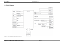
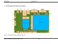
MSC Q7-MB-EP3
MSC QsevenTM Baseboard
REV 1.2
May 06th, 2011
[email protected]
www.msc-ge.com/boards
MSC Q7-MB-EP3
User Manual Rev 1.2
Preface
Copyright Notice
Copyright © 2010 MSC Vertriebs GmbH. All rights reserved.
Copying of this document, and giving it to others and the use or communication of the
contents thereof, are forbidden without express authority. Offenders are liable to the payment
of damages.
All rights are reserved in the event of the grant of a patent or the registration of a utility model
or design.
Important Information
This documentation is intended for qualified audience only. The product described herein is
not an end user product. It was developed and manufactured for further processing by
trained personnel.
Disclaimer
Although this document has been generated with the utmost care no warranty or liability for
correctness or suitability for any particular purpose is implied. The information in this
document is provided “as is” and is subject to change without notice.
EMC Rules
This unit has to be installed in a shielded housing. If not installed in a properly shielded
enclosure, and used in accordance with the instruction manual, this product may cause radio
interference in which case the user may be required to take adequate measures at his or her
own expense.
Trademarks
All used product names, logos or trademarks are property of their respective owners.
Certification
MSC Vertriebs GmbH is certified according to DIN EN ISO 9001:2000 standards.
Life-Cycle-Management
MSC products are developed and manufactured according to high quality standards. Our lifecycle-management assures long term availability through permanent product maintenance.
Technically necessary changes and improvements are introduced if applicable. A productchange-notification and end-of-life management process assures early information of our
customers.
Product Support
MSC engineers and technicians are committed to provide support to our customers
whenever needed.
Before contacting the Technical Support, please consult the respective pages on our web
site at www.msc-ge.com/support-boards for the latest documentation, drivers and software
downloads.
If the information provided there does not solve your problem, please contact our Technical
Support:
Email: [email protected]
Phone: +49 8165 906-200
Design Center Neufahrn
Copyright © 2010 MSC Vertriebs GmbH. All rights reserved
Page 2
MSC Q7-MB-EP3
User Manual Rev 1.2
Contents
1
General Information ........................................................................................................................................ 6
1.1
Revision History...................................................................................................................................... 6
1.2
Reference Documents ............................................................................................................................. 6
1.3
Definitions and Abbreviations ................................................................................................................ 7
2
Introduction ..................................................................................................................................................... 8
2.1
QsevenTM Product Description ................................................................................................................ 8
2.2
Features ................................................................................................................................................... 8
2.3
Block Diagram ........................................................................................................................................ 9
2.4
Positioning of Connectors and Jumpers ................................................................................................ 10
2.5
Dimensions............................................................................................................................................ 12
3
Hardware ....................................................................................................................................................... 13
3.1
QsevenTM Connector (X201) ................................................................................................................. 13
3.2
VGA Interface (X301) .......................................................................................................................... 16
3.3
LCD Panel LVDS Interface .................................................................................................................. 17
3.3.1
JILI30 Connector .......................................................................................................................... 17
3.3.2
Backlight Inverter Interface (X802) .............................................................................................. 18
3.3.3
LVDS EEPROM ............................................................................................................................ 19
3.3.4
LVDS Panel Jumper settings ......................................................................................................... 20
3.3.4.1 Display power Jumper .................................................................................................................. 20
3.3.4.2 Backlight power selection jumper ................................................................................................. 21
3.3.4.3 Backlight Enable polarity selection jumper .................................................................................. 22
3.3.4.4 Backlight brightness peak voltage level jumper ............................................................................ 23
3.3.4.5 Backlight brightness control jumpers............................................................................................ 24
3.3.4.6 EDID EEPROM address select jumper......................................................................................... 25
3.4
SATA-Interface (X501, X503) ............................................................................................................. 26
3.4.1
SATA LED ..................................................................................................................................... 26
3.5
Ethernet (X506)..................................................................................................................................... 27
3.5.1
Wake on LAN................................................................................................................................. 27
3.6
USB Topology ...................................................................................................................................... 28
3.6.1
Mini USB Connector (X601) ......................................................................................................... 28
3.6.2
Dual USB Connector (X602)......................................................................................................... 29
3.6.3
Internal Dual USB-Connector (X603).......................................................................................... 30
3.6.4
Internal single USB Connector (X604) ......................................................................................... 31
3.6.5
USB Power Supply ........................................................................................................................ 31
3.7
Touch Interface (X1001, X1002) .......................................................................................................... 32
3.7.1
Touch control jumper (J1001)....................................................................................................... 33
3.8
PCIe Mini Card (X502) ......................................................................................................................... 34
3.8.1
Wireless operation on mini PCIe add-in cards (J501) .................................................................. 34
3.8.2
PCIe Mini Card Status LEDs ........................................................................................................ 34
3.9
RS-232 COM port (X701)..................................................................................................................... 35
3.10 Audio interface ...................................................................................................................................... 36
3.10.1
Stereo Line out (X402) .................................................................................................................. 36
3.10.2
HD Audio (X403) .......................................................................................................................... 37
3.11 CAN Interface (X905)........................................................................................................................... 38
3.12 SPI Interface (X903) ............................................................................................................................. 39
3.13 JTAG Interface (X901) ......................................................................................................................... 40
3.14 SMBUS, I2C Interface (X902).............................................................................................................. 41
3.15 Beeper ................................................................................................................................................... 42
3.16 Battery / Goldcap .................................................................................................................................. 42
3.17 SDIO Card............................................................................................................................................. 43
3.18 Power (X1101) ...................................................................................................................................... 44
3.18.1
12V LVDS Backlight jumper (J1201) ............................................................................................ 45
3.18.2
RESET Button................................................................................................................................ 45
3.18.3
Sleep button ................................................................................................................................... 46
3.18.4
Power button ................................................................................................................................. 46
3.18.5
Lid Button ...................................................................................................................................... 47
3.18.6
Suspend Signal .............................................................................................................................. 47
3.18.7
S3 Cold/ S3 Hot feature (J1101) ................................................................................................... 48
3.19 Power LEDs ...................................................................................................................................... 48
Design Center Neufahrn
Copyright © 2010 MSC Vertriebs GmbH. All rights reserved
Page 3
MSC Q7-MB-EP3
User Manual Rev 1.2
Figures
Figure 1
Figure 2
Figure 3
Figure 4
Block Diagram Q7-MB-EP3 baseboard ............................................................. 9
Positioning of Connectors and Jumpers (Top view) .......................................10
Positioning of Connectors (Bottom view) ........................................................11
MSC Q7 MB EP3 Board Dimension ..................................................................12
Design Center Neufahrn
Copyright © 2010 MSC Vertriebs GmbH. All rights reserved
Page 4
MSC Q7-MB-EP3
User Manual Rev 1.2
Tables
Table 1 Pinout QsevenTM Connector X201 ...........................................................................13
Table 2 Pinout VGA Connector X301 ...................................................................................16
Table 3 Pinout JILI30 Connector X801 .................................................................................17
Table 4 Pinout Backlight Connector X802 ............................................................................19
Table 5 Jumper settings LCD Panel Power X803 .................................................................20
Table 6 Jumper settings Backlight power X803 ....................................................................21
Table 7 Jumper settings Backlight Enable Polarity X803 ......................................................22
Table 8 Jumper settings Backlight Brightness Voltage X803 ................................................23
Table 9 Jumper settings Backlight Brightness Control X803 .................................................24
Table 10 Jumper settings EDID EEPROM Address X803 ....................................................25
Table 11 Assignment SATA Channel to Connector ..............................................................26
Table 12 Pinout SATA ..........................................................................................................26
Table 13 Assignment USB Ports .........................................................................................28
Table 14 Jumper option USB Client J601 .............................................................................29
Table 15 Pinout Dual USB Connector X603 .........................................................................30
Table 16 Pinout Internal USB Connector X604 .....................................................................31
Table 17 Pinout 4 wire Touch X1001, X1002........................................................................32
Table 18 Pinout 5 Wire Touch X1003 ...................................................................................33
Table 19 Jumper Touch Select J1001 ..................................................................................33
Table 20 Jumper mini PCIe Wireless Operation J501 ..........................................................34
Table 21 Pinout COM ...........................................................................................................35
Table 22 Pinout HD Audio Connector X403..........................................................................37
Table 23 Pinout CAN X905 ..................................................................................................38
Table 24 Pinout SPI X903 ....................................................................................................39
Table 25 Pinout JTAG X901 .................................................................................................40
Table 26 Pinout SMBUS I2C X902 .......................................................................................41
Table 27 Pinout Power Connector X1101 .............................................................................44
Table 28 Function J1201 ......................................................................................................45
Table 29 Function J1101 ......................................................................................................48
Design Center Neufahrn
Copyright © 2010 MSC Vertriebs GmbH. All rights reserved
Page 5
MSC Q7-MB-EP3
User Manual Rev 1.2
1
General Information
1.1
Revision History
1.2
Rev.
Date
1.0
17.08.2010
Preliminary Release for website.
Description
1.1
17.01.2011
JTAG Table correction.
1.2
06.05.2011
Part number added for Power X1101 connector. X604 USB added.
Reference Documents
[1]
[2]
[3]
[4]
[5]
[6]
[7]
[8]
[9]
TM
Qseven Module Specification
Revision 1.1
http://www.Qseven-standard.org/
PCI Local Bus Specification Rev. 2.1
PCI21.PDF
Last update: June 1st, 1995
http://www.pcisig.com
JILI Specification
Jilim120.pdf
Last update: April 7th, 2003
http://www.jumptec.de/product/data/jili/index.html
Digital Video Interface DVI
dvi_10.pdf
Rev. 1.0 April 2nd, 1999
http://www.ddwg.org/
Serial ATA Specification
Serial ATA 1.0 gold.pdf
Last update: August 29th, 2002 Rev.1.0
http://www.sata-io.org/
IEEE Std. 802.3-2002
802.3-2002.pdf
http://www.ieee.org
Universal Bus Specification
usb_20.pdf
Last update: April 27th, 2000
http://www.usb.org
SDIO Card Specification
Simplified_SDIO_Card_Spec.pdf
Last update: February 8th, 2007
http://www.sdcard.org
PCIe Mini Card Specification
http://www.pcisig.com
Design Center Neufahrn
Copyright © 2010 MSC Vertriebs GmbH. All rights reserved
Page 6
MSC Q7-MB-EP3
1.3
User Manual Rev 1.2
Definitions and Abbreviations
COM
RTC
PCI
SATA
USB
LVDS
JILI
LAN
VGA
LPC
POST
SMBus
MDI
Computer-On-Module
Real Time Clock
Peripheral Component Interconnect
Serial Advanced Technology Attachment
Universal Serial Bus
Low Voltage Differential Signaling
JUMPtec Intelligent LVDS Interface
Local Area Network
Video Graphics Array
Low Pin Count
Power on self test
System Management Bus
Medium Dependent Interface
Design Center Neufahrn
Copyright © 2010 MSC Vertriebs GmbH. All rights reserved
Page 7
MSC Q7-MB-EP3
User Manual Rev 1.2
2 Introduction
2.1
QsevenTM Product Description
TM
Qseven modules are off the shelf compact, highly integrated Computer on Module devices
TM
which are designed to connect to a carrier baseboard. The Qseven standard is supported by
multiple companies and defines a standardized square board size of 70x70 mm with s defined
interface to the carrier board. The connection to the carrier board is made with an MXM type edge
connector.
TM
Typically a Qseven module includes CPU, chipset, memory, Ethernet controller, BIOS flash,
SATA and USB controller. Interface controllers or connectors (e.g. RJ45) are implemented on the
TM
baseboard on to which the Qseven module is mounted.
In addition to the power supply also signals for PCIe, SATA, USB, LPC etc. are routed over the
TM
Qseven edge connector.
Thanks to the standardized mechanics and interfaces the system can be scaled to the
performance requirements of the application. Despite the modular concept the system design is
very flat and compact.
TM
Qseven
modules require a baseboard for proper operation.
TM
This manual describes the Qseven Embedded Platform (MSC Q7-MB-EP3), which is a
TM
baseboard designed for small production runs or as a small evaluation platform for Qseven
modules.
2.2
Features
VGA display interface
LVDS LCD panel interface, using the standard JILI30 connector
5 Pin LCD panel Backlight Connector
High Definition Audio using Via VT1708A
·
Line Out
·
HDA Front Panel
2 SATA channel connectors, each capable of 300MB/s
6 Port USB interface
·
2 USB type A connectors
·
1 mini USB connector, which can be configured as host or client
·
3 USB interfaces on on-board pin header connector
10/100/1000 Base-T LAN interface
RS232 Com Port (using LPC SuperIO W83627HF)
PCIe Mini Card slot
SD card Socket
SPI connector
CAN connector
JTAG connector
Power supply with variable Input Supply Voltage from 10 to 28 V
Beeper connector(optional)
Resistive Touch controller
·
Two 4-wire Connectors
·
One 5-wire Connect
Battery / goldcap option for RTC (Real Time Clock).
Design Center Neufahrn
Copyright © 2010 MSC Vertriebs GmbH. All rights reserved
Page 8
MSC Q7-MB-EP3
2.3
User Manual Rev 1.2
Block Diagram
Figure 1 Block Diagram Q7-MB-EP3 baseboard
Design Center Neufahrn
Copyright © 2010 MSC Vertriebs GmbH. All rights reserved
Page 9
MSC Q7-MB-EP3
2.4
User Manual Rev 1.2
Positioning of Connectors and Jumpers
Figure 2 Positioning of Connectors and Jumpers (Top view)
Design Center Neufahrn
Copyright © 2010 MSC Vertriebs GmbH. All rights reserved
Page 10
MSC Q7-MB-EP3
User Manual Rev 1.2
Figure 3 Positioning of Connectors (Bottom view)
Design Center Neufahrn
Copyright © 2010 MSC Vertriebs GmbH. All rights reserved
Page 11
MSC Q7-MB-EP3
2.5
User Manual Rev 1.2
Dimensions
Dimension:
148.02 mm x 102.22 mm
Board Thickness:
1.8 mm + /-10%
Drill hole positioning tolerance:
+/- 0.1mm in X and Y
Drill hole diameter tolerance:
+ 0.1 mm
Max height of component on Top side:
16.8mm
Max height of component on Bottom side: 5.4mm
Figure 4 MSC Q7 MB EP3 Board Dimension
Design Center Neufahrn
Copyright © 2010 MSC Vertriebs GmbH. All rights reserved
Page 12
MSC Q7-MB-EP3
User Manual Rev 1.2
3 Hardware
TM
NOTE: Not all Qseven modules may support all connectors and functionality available
on the MSC Q7-MB-EP3 embedded platform baseboard.
3.1
QsevenTM Connector (X201)
Specification:
Reference :
X201 Foxconn AS0B326-S78N-7F
Mating
:
PCB Q7 Module
Pinout
:
Refer to Qseven
Table 1 Pinout Qseven
Row A
1
3
5
7
9
11
13
15
17
19
21
23
KEY
25
27
29
31
33
TM
TM
specification [1]
Connector X201
GND
GBE_MDI3GBE_MDI3+
GBE_LINK100#
GBE_MDI1GBE_MDI1+
GBE_LINK#
GBE_CTREF
WAKE#
SUS_STAT#
SLP_BTN#
GND
GND
BATLOW#
SATA0_TX+
SATA0_TXSATA_ACT#
Row B
2
4
6
8
10
12
14
16
18
20
22
24
KEY
26
28
30
32
34
Design Center Neufahrn
Copyright © 2010 MSC Vertriebs GmbH. All rights reserved
GND
GBE_MDI2GBE_MDI2+
GBE_LINK1000#
GBE_MDI0GBE_MDI0+
GBE_ACT#
SUS_S5#
SUS_S3#
PWRBTN#
LID_BTN#
GND
PWGIN
RSTBTN#
SATA1_TX+
SATA1_TXGND
Page 13
MSC Q7-MB-EP3
35
37
39
41
43
45
47
49
51
53
55
57
59
61
63
65
67
69
71
73
75
77
79
81
83
85
87
89
91
93
95
97
99
101
103
105
107
109
111
113
115
117
119
121
123
125
127
129
131
133
135
137
139
141
143
145
147
149
151
153
User Manual Rev 1.2
SATA0_RX+
SATA0_RXGND
BIOS_DISABLE#
SDIO_CD#
SDIO_CMD
SDIO_PWR#
SDIO_DAT0
SDIO_DAT2
SDIO_DAT4
SDIO_DAT6
GND
HDA_SYNC
HDA_RST#
HDA_BITCLK
HDA_SDI
HDA_SDO
THRM#
THRMTRIP#
GND
USB_P7USB_P7+
USB_6_7_OC#
USB_P5USB_P5+
USB_2_3_OC#
USB_P3USB_P3+
USB_CC
USB_P1USB_P1+
GND
LVDS_A0+
LVDS_A0LVDS_A1+
LVDS_A1LVDS_A2+
LVDS_A2LVDS_PPEN
LVDS_A3+
LVDS_A3GND
LVDS_A_CLK+
LVDS_A_CLKLVDS_BLT_CTRL
LVDS_DID_DAT
LVDS_DID_CLK
CAN0_TX
SDVO_BCLK+
SDVO_BCLKGND
SDVO_GREEN+
SDVO_GREENGND
SDVO_BLUE+
SDVO_BLUEGND
SDVO_RED+
SDVO_REDHDMI_HPD#
36
38
40
42
44
46
48
50
52
54
56
58
60
62
64
66
68
70
72
74
76
78
80
82
84
86
88
90
92
94
96
98
100
102
104
106
108
110
112
114
116
118
120
122
124
126
128
130
132
134
136
138
140
142
144
146
148
150
152
154
Design Center Neufahrn
Copyright © 2010 MSC Vertriebs GmbH. All rights reserved
SATA1_RX+
SATA1_RXGND
SDIO_CLK#
SDIO_LED
SDIO_WP
SDIO_DAT1
SDIO_DAT3
SDIO_DAT5
SDIO_DAT7
SDIO_PWRSEL
GND
SMB_CLK
SMB_DAT
SMB_ALERT#
I2C_CLK
I2C_DAT
WDTRIG#
WDOUT
GND
USB_P6USB_P6+
USB_4_5_OC#
USB_P4USB_P4+
USB_0_1_OC#
USB_P2USB_P2+
RSVD
USB_P0USB_P0+
GND
LVDS_B0+
LVDS_B0LVDS_B1+
LVDS_B1LVDS_B2+
LVDS_B2LVDS_BLEN
LVDS_B3+
LVDS_B3GND
LVDS_B_CLK+
LVDS_B_CLKRSVD
LVDS_BLC_DAT
LVDS_BLC_CLK
CAN0_RX
SDVO_INT+
SDVO_INTGND
SDVO_FLDSTALL+
SDVO_FLDSTALLGND
SDVO_TVCLKIN+
SDVO_TVCLKINGND
SDVO_CTRL_DAT
SDVO_CTRL_CLK
DP_HPD#
Page 14
MSC Q7-MB-EP3
155
157
159
161
163
165
167
169
171
173
175
177
179
181
183
185
187
189
191
193
195
197
199
201
203
205
207
209
211
213
215
217
219
221
223
225
227
229
User Manual Rev 1.2
PCIE_CLK_REF+
PCIE_CLK_REFGND
PCIE3_TX+
PCIE3_TXGND
PCIE2_TX+
PCIE2_TXEXCD0_PERST#
PCIE1_TX+
PCIE1_TXEXCD0_CPPE#
PCIE0_TX+
PCIE0_TXGND
LPC_AD0
LPC_AD2
LPC_CLK
SERIRQ
VCC_RTC
FAN_TACHOIN
GND
SPI_MOSI
SPI_MISO
SPI_SCK
VCC_5V_SB
MFG_NC0
MFG_NC1
VCC
VCC
VCC
VCC
VCC
VCC
VCC
VCC
VCC
VCC
156
158
160
162
164
166
168
170
172
174
176
178
180
182
184
186
188
190
192
194
196
198
200
202
204
206
208
210
212
214
216
218
220
222
224
226
228
230
Design Center Neufahrn
Copyright © 2010 MSC Vertriebs GmbH. All rights reserved
PCIE_WAKE#
PCIE_RST#
GND
PCIE3_RX+
PCIE3_RXGND
PCIE2_RX+
PCIE2_RXEXCD1_PERST#
PCIE1_RX+
PCIE1_RXEXCD1_CPPE#
PCIE0_RX+
PCIE0_RXGND
LPC_AD1
LPC_AD3
LPC_FRAME#
LPC_LDRQ#
SPKR
FAN_PWMOUT
GND
SPI_CS0
SPI_CS1
RSVD
VCC_5V_SB
MFG_NC2
MFG_NC3
VCC
VCC
VCC
VCC
VCC
VCC
VCC
VCC
VCC
VCC
Page 15
MSC Q7-MB-EP3
3.2
User Manual Rev 1.2
VGA Interface (X301)
The VGA signals are generated via a Chrontel CH7317B SDVO to VGA display controller.
Specification:
References
:
X301
SUYIN 070207FR015S218ZA
Mating
:
VGA-Monitor
Table 2 Pinout VGA Connector X301
Pin
1
2
3
4
5
6
7
8
9
10
11
12
13
14
15
Signal name
RED
GREEN
BLUE
RSVD
GND
RGND
GGND
BGND
+5V
SGND
ID0
SDA
HSYNC
VSYNC
SCL
Design Center Neufahrn
Copyright © 2010 MSC Vertriebs GmbH. All rights reserved
Function
Signal red
Signal green
Signal blue
reserved
Ground digital
Ground red
Ground green
Ground blue
+5V VDC
Sync. Ground
Monitor ID Bit 0 (optional)
DDC Data
Horizontal Sync.
Vertical Sync.
DDC Clock
Page 16
MSC Q7-MB-EP3
3.3
User Manual Rev 1.2
LCD Panel LVDS Interface
3.3.1 JILI30 Connector
LCD/TFT displays with LVDS inputs can be connected via the JILI30 connector.
Two 24 bit LVDS channels are available on this 32-pin header. Single channel and 18bit displays
are also supported using the appropriate cables.
TM
Note: Support of single/dual channel and 18/24 bit will depend on the Qseven
module used.
The Supply voltage of the LVDS Signal can be adjusted with a jumper on the X803 header.
Please contact [email protected] for assistance in finding appropriate
display/backlight inverter and cable sets for your application requirements
PIN1
Specification:
References
:
X801
Hirose MDF76GW-30S-1H(55)
Mating
:
Cable Plug MDF76-30P-1C
Table 3 Pinout JILI30 Connector X801
Pin
1
2
3
4
5
6
7
8
9
10
11
Signal name
LVDS_A0LVDS_A0+
LVDS_A1LVDS_A1+
LVDS_A2LVDS_A2+
GND
LVDS_A_CLKLVDS_A_CLK+
LVDS_A3LVDS_A3+
Function
LVDS Negative data signal (-)
LVDS Positive data signal (+)
LVDS Negative data signal (-)
LVDS Positive data signal (+)
LVDS Negative data signal (-)
LVDS Positive data signal (+)
Ground
LVDS Negative clock signal (-)
LVDS Positive clock signal (+)
LVDS Negative data signal (-)
LVDS Positive data signal (+)
Design Center Neufahrn
Copyright © 2010 MSC Vertriebs GmbH. All rights reserved
Page 17
MSC Q7-MB-EP3
User Manual Rev 1.2
12
13
14
15
16
17
18
19
20
21
22
23
24
25
26
27
28
29
30
LVDS_B0LVDS_B0+
GND
LVDS_B1LVDS_B1+
GND
LVDS_B2LVDS_B2+
LVDS_B_CLKLVDS_B_CLK+
LVDS_B3LVDS_B3+
GND
PANEL_I2C_DAT
LVDS_PPEN
PANEL_I2C_CLK
VCC
VCC
VCC
LVDS Negative data signal (-)
LVDS Positive data signal (+)
Ground
LVDS Negative data signal (-)
LVDS Positive data signal (+)
Ground
LVDS Negative data signal (-)
LVDS Positive data signal (+)
LVDS Negative clock signal (-)
LVDS Positive clock signal (+)
LVDS Negative data signal (-)
LVDS Positive data signal (+)
Ground
I2C Signal
Panel Power Enable
I2C Signal
Power Supply: +3.3V or +5V or +12V
Power Supply: +3.3V or +5V or +12V
Power Supply: +3.3V or +5V or +12V
3.3.2 Backlight Inverter Interface (X802)
The backlight inverter (for CCFL) or LED driver (for CCD) is attached using this 5 pin
connector.
The supply voltage (VCC) of the backlight can be selected with a jumper on X803 for 12V, 5V
or 3.3V.
The inverter or LED driver can be turned on or off using the BLON signal. The polarity of the
BLON signal is selected with a jumper on X803.
The brightness of the backlight is controlled via the VCON signal.
TM
The LVDS_BKLT_CTRL signal coming from the Qseven module usually provides a PWM
signal. Depending on the settings of jumpers on X803 the following brightness control signals
can be applied:
-
PWM signal either inverted or non-inverted
-
The analog signal level is derived either from the inverted or from the noninverted PWM signal. (The PWM signal is integrated and then limited to the
selected peak voltage of the backlight inverter).
The peak level of the brightness signal can be selected with a jumper on X803 to be either
3.3V or 5V.
The maximum brightness (with 0V or with 3.3V/5V) will depend on the Inverter or LED
backlight type used.
See section 3.3.4 for LVDS Panel Jumper settings.
Design Center Neufahrn
Copyright © 2010 MSC Vertriebs GmbH. All rights reserved
Page 18
MSC Q7-MB-EP3
User Manual Rev 1.2
Specification:
References
:
X802
Würth Elektronik 653105131822
Mating
:
Cable Plug 653005113322
Table 4 Pinout Backlight Connector X802
Pin
1
2
3
4
5
Signal name
VCC
GND
BLON
VCON
GND
Function
Backlight power supply
Ground
Backlight On/Off control
Brightness control
Ground
3.3.3 LVDS EEPROM
To store configuration data for the display, a serial EEPROM is connected to the LVDS I2C
bus -signals LVDS_I2C_CK and LVDS_I2C_DAT.
To avoid conflicts with a configuration EEPROM on the connected display, this EEPROM can
be mapped to an unused address space. The address can be configured with a jumper on
X803.
See section 3.3.4 for Jumper settings.
Design Center Neufahrn
Copyright © 2010 MSC Vertriebs GmbH. All rights reserved
Page 19
MSC Q7-MB-EP3
User Manual Rev 1.2
3.3.4 LVDS Panel Jumper settings
3.3.4.1 Display power Jumper
The power supply voltage for the LCD panel (NOT the backlight) is selected with a jumper on the
jumper block X803. The software control of the LCD panel enable signal can be bypassed by inserting
a jumper on pins 1-2.
Table 5 Jumper settings LCD Panel Power X803
Function
X803 Pins
Power always on*
1-2
+3.3 V
3-4 (default)
+5.0 V
5-6
+12V
7-8
*Panel is no longer enabled by LVDS_VDD_EN# signal, but is permanently enabled if this jumper
is installed.
Design Center Neufahrn
Copyright © 2010 MSC Vertriebs GmbH. All rights reserved
Page 20
MSC Q7-MB-EP3
User Manual Rev 1.2
3.3.4.2 Backlight power selection jumper
The backlight power for the inverter or LED driver is selected using jumpers on X803.
Table 6 Jumper settings Backlight power X803
Backlight Voltage
+3.3 V / 1A
+5.0 V / 1A
+12.0 V / 1A
X803 Pins
9-10
(default)
11-12
13-14
Design Center Neufahrn
Copyright © 2010 MSC Vertriebs GmbH. All rights reserved
Page 21
MSC Q7-MB-EP3
User Manual Rev 1.2
3.3.4.3 Backlight Enable polarity selection jumper
The polarity of the backlight enable signal (BLON) can be selected using jumpers on X803.
Table 7 Jumper settings Backlight Enable Polarity X803
Function
BLON# (low active)
BLON (high active)
X803 Pins
16-18 (default)
18-20
Design Center Neufahrn
Copyright © 2010 MSC Vertriebs GmbH. All rights reserved
Page 22
MSC Q7-MB-EP3
User Manual Rev 1.2
3.3.4.4 Backlight brightness peak voltage level jumper
This jumper selects the voltage range for the signal level used for the brightness control. This signal
can be either a PWM signal or an analog voltage level depending on the settings of jumpers on X803.
The voltage range can be either 3.3V or 5V
Table 8 Jumper settings Backlight Brightness Voltage X803
Function
3.3V Peak level
5V Peak level
X803 Pins
15-17 (default)
17-19
Design Center Neufahrn
Copyright © 2010 MSC Vertriebs GmbH. All rights reserved
Page 23
MSC Q7-MB-EP3
User Manual Rev 1.2
3.3.4.5 Backlight brightness control jumpers
The jumpers on X803 are used in combination to select the type of brightness control signal used for
TM
the LCD panel backlight inverter or LED driver. The signal coming from the Qseven module is
typically a PWM signal. This signal can be passed through unmodified, or inverted. It can also be
converted to an analog voltage level for backlights which do not use a PWM signal for brightness
control.
Table 9 Jumper settings Backlight Brightness Control X803
X803
22-24
22-24
24-26
24-26
X803
21-23
23-25
21-23
23-25
Output signal
Analog level based on inverted PWM signal
PWM signal (non-inverted) (default)
Analog level based on non-inverted PWM signal
PWM signal (inverted)
Design Center Neufahrn
Copyright © 2010 MSC Vertriebs GmbH. All rights reserved
Page 24
MSC Q7-MB-EP3
User Manual Rev 1.2
3.3.4.6 EDID EEPROM address select jumper
An EDID EEPROM is available on the baseboard in order to configure a customized setting for an
LCD panel which is not available in the default BIOS LCD panel entries.
Table 10 Jumper settings EDID EEPROM Address X803
Function
EDID EEPROM disabled
EDID EEPROM enabled
X803 pins
28-30 Removed
28-30 Installed
Design Center Neufahrn
Copyright © 2010 MSC Vertriebs GmbH. All rights reserved
(default)
Page 25
MSC Q7-MB-EP3
3.4
User Manual Rev 1.2
SATA-Interface (X501, X503)
For the connection of SATA drives there are two SATA interfaces
Table 11 Assignment SATA Channel to Connector
SATA Channel
SATA 0
SATA 1
References
X501
X503
Specification:
References
:
X501, X503
FCI 59334-002-LF
Mating
:
SATA-cable
Pinout
:
Refer to SATA Specification [8, page 46, table 3]
Table 12 Pinout SATA
Con
1
2
3
4
5
6
7
Signal name
GND
TX+
TXGND
RXRX+
GND
Function
Ground
SATA Positive transmit signal (+)
SATA Negative transmit signal (-)
Ground
SATA Negative transmit signal (-)
SATA Positive transmit signal (+)
Ground
TM
Note: Availability of the SATA Ports will depend on the Qseven
module used.
3.4.1 SATA LED
An onboard LED (LED505) is provided to indicate activity on the SATA port.
Design Center Neufahrn
Copyright © 2010 MSC Vertriebs GmbH. All rights reserved
Page 26
MSC Q7-MB-EP3
3.5
Ethernet
User Manual Rev 1.2
(X506)
The MSC Q7-MB-EP3 can be connected to a local area network via a 10/100/1000 Base-T
TM
interface. A 1000Base-T transformer is assembled on the baseboard; hence the Qseven CPU
module must support Gigabit Ethernet.
Specification:
References
:
X506 Foxconn JMF3811E-2102-4F
Pinout
:
Refer to IEEE Std. 802.3 [9, section three, page 225]
3.5.1 Wake on LAN
The system can be wake up from the sleep S3(Suspend to RAM) state by sending the magic packet
over Ethernet.
Design Center Neufahrn
Copyright © 2010 MSC Vertriebs GmbH. All rights reserved
Page 27
MSC Q7-MB-EP3
3.6
User Manual Rev 1.2
USB Topology
TM
Eight USB ports are normally provided by the Qseven
module.
The assignment of the ports is defined in the following table:
Table 13 Assignment USB Ports
Signal
Source
USB[0]+
USB[0]USB[1]+
USB[1]USB[2]+
USB[2]USB[3]+
USB[3]USB[4]+
USB[4]USB[5]+
USB[5]USB[6]+
USB[6]USB[7]+
USB[7]-
Qseven
Target
Remark
TM
connector USB0
X603
On-board 10 Pin Header
TM
connector USB1
X601
Mini USB Client / Host
TM
connector USB2
X602
Dual USB Connector
TM
connector USB3
X602
Dual USB Connector
TM
connector USB4
X604
On-board 5 Pin Header
TM
connector USB5
X1001/X1002
Touch controller
TM
connector USB6
X502
PCIe Mini Card
TM
connector USB7
X603
On-board 10 Pin Header
Qseven
Qseven
Qseven
Qseven
Qseven
Qseven
Qseven
TM
Note : USB6 and USB7 for current Qseven modules support USB 2.0 only and will NOT
work with USB 1.1 devices - e.g. Keyboard, Mouse, …
3.6.1 Mini USB Connector (X601)
Design Center Neufahrn
Copyright © 2010 MSC Vertriebs GmbH. All rights reserved
Page 28
MSC Q7-MB-EP3
User Manual Rev 1.2
Specification:
References
:
X601
Molex 67803-8020
Mating
:
Mini USB-cable
Pinout
:
according to USB specification 2.0 [7]
The Mini USB port can be configured as a client or host using jumper J601.
Table 14 Jumper option USB Client J601
Function
USB mini AB client
USB mini AB host
J601
removed
inserted (default)
3.6.2 Dual USB Connector (X602)
Specification:
References
:
X602
Neltron 5075AR-08B-BK
Mating
:
USB-A cable
Pinout
:
according to USB specification 2.0 [7]
Design Center Neufahrn
Copyright © 2010 MSC Vertriebs GmbH. All rights reserved
Page 29
MSC Q7-MB-EP3
User Manual Rev 1.2
3.6.3 Internal Dual USB-Connector (X603)
Pin 2
Pin 10
Pin 1
Specification:
References
:
X603 male connector 2x5pin pitch 2.54mm
Mating
:
female crimp-connector Reference FCI 65043-032
Table 15 Pinout Dual USB Connector X603
Pin
Pin
Signal
Signal
1
USB_VCC0
2
USB_VCC7
3
USB_R04
USB_R75
USB_R0+
6
USB_R7+
7
GND
8
GND
9
No Pin
10
NC
TM
USB7 for current Qseven modules supports USB 2.0 only and will NOT work with USB 1.1
devices - e.g. Keyboard, Mouse…
Design Center Neufahrn
Copyright © 2010 MSC Vertriebs GmbH. All rights reserved
Page 30
MSC Q7-MB-EP3
User Manual Rev 1.2
3.6.4 Internal single USB Connector (X604)
Specification:
References
:
X604 CAB 1001-161-005-RoHS
Mating
:
female crimp-connector Reference FCI 65039-032
Table 16 Pinout Internal USB Connector X604
Pin
1
2
3
4
5
Signal
USB_VCC4
USB_R4USB_R4+
GND
No Connect
3.6.5 USB Power Supply
The power supplies are protected by USB power switches. In addition to that the input voltages of
the USB power switches are protected by resettable fuses.
The USB power switches have the following features:
The output current is limited to 500mA per port
A signal to detect overcurrent is generated for each pair of ports
o
USB0 and USB1 have one common signal to detect overcurrent
o
USB2 and USB3 have one common signal to detect overcurrent
o
USB4 and USB5 have one common signal to detect overcurrent
o
USB6 and USB7 have one common signal to detect overcurrent
Design Center Neufahrn
Copyright © 2010 MSC Vertriebs GmbH. All rights reserved
Page 31
MSC Q7-MB-EP3
3.7
User Manual Rev 1.2
Touch Interface (X1001, X1002)
A Resistive Touch Controller for 4-Wire and 5-Wire touch screens is integrated on the base board
The touch controller is the HS12-100S0O from Hampshire. The latest device drivers for the controller
can be downloaded from www.msc-ge.com/support-boards
The X+, X- and Y+, Y- signals are connected to X1001, X1002 and X1003, so whichever connector is
most convenient for the touch interface can be used.
Specification:
References:
X1001 (4-Wire eTurbo-Touch pinning) Hirose FH12-10-4-SA-1SH
X1002 (4-Wire AUO-Touch pinning)
Hirose FH12-10-4-SA-1SH
FPC/FCC pitch 0.5mm x
Mating:
0.3mm
X1001 & 1002
Mating:
X1003
female crimp-connector Reference FCI 65039-032
Table 17 Pinout 4 wire Touch X1001, X1002
X1001 4-Wire eTurbo-Touch
Pin
Signal
1
Y+
2
X3
Y4
X+
X1002 4-Wire AUO-Touch
Pin
Signal
1
2
3
4
Design Center Neufahrn
Copyright © 2010 MSC Vertriebs GmbH. All rights reserved
X+
Y+
XY-
Page 32
MSC Q7-MB-EP3
User Manual Rev 1.2
Specification:
References:
X1003 (5-Wire) CAB 1006-141-005
Mating:
X1003
female crimp-connector Reference FCI 65039-032
Table 18 Pinout 5 Wire Touch X1003
X1003 5-Wire Wire eTurbo-Touch
Pin
Signal
1
Y+
2
X+
3
5W
4
X5
YPlease contact [email protected] for assistance in finding appropriate displays with
touch screen for your application requirements
3.7.1 Touch control jumper (J1001)
The touch controller interface can be switched between 4 and five-wire using this jumper.
Table 19 Jumper Touch Select J1001
Function
5-Wire enabled
4-Wire enabled
J1001
removed
installed (default)
Design Center Neufahrn
Copyright © 2010 MSC Vertriebs GmbH. All rights reserved
Page 33
MSC Q7-MB-EP3
3.8
PCIe Mini Card
User Manual Rev 1.2
(X502)
Specification:
References
:
X502
Pinout
:
Refer to Mini PCIe Mini Card Specification [9]
3.8.1 Wireless operation on mini PCIe add-in cards (J501)
A jumper is provided to enable / disable wireless operation on the mini PCIe card.
Table 20 Jumper mini PCIe Wireless Operation J501
Function
wireless operation enabled
wireless operation disabled
J501
removed (default)
installed
3.8.2 PCIe Mini Card Status LEDs
The Q7-MB-EP3 base board has 3 LEDs to display the state of an add-in mini PCIe card with
wireless capabilities.
LED0501 WWAN LED
LED0502 WLAN LED
LED0503 WPAN LED
Design Center Neufahrn
Copyright © 2010 MSC Vertriebs GmbH. All rights reserved
Page 34
MSC Q7-MB-EP3
3.9
User Manual Rev 1.2
RS-232 COM port (X701)
RS232 standard
RS232 over LPC Super IO Chip (W83627HF).
RS232 transceiver ESD protected +/- 15kV
EMC improvement by using EMI filters in the signal lines
Specification:
References
:
X701 (COM1) Kycon K22X-E9P-N30
Mating
:
Cable RS232 D-SUB 9pin female
Table 21 Pinout COM
Pin
1
2
3
4
5
6
7
8
9
Signal name
DCD#
RXD
TXD
DTR#
GND
DSR#
RTS#
CTS#
RI#
Function
Data Carrier Detect
Receive Data
Transmit Data
Data Terminal Ready
Ground
Data Set Ready
Request To Send
Clear To Send
Ring Indicator
Design Center Neufahrn
Copyright © 2010 MSC Vertriebs GmbH. All rights reserved
Page 35
MSC Q7-MB-EP3
User Manual Rev 1.2
3.10 Audio interface
TM
The Via VT1708A High Definition Audio codec is connected to the HDA link of the Qseven
module.
The following LF signals are provided by the HDA codec:
Stereo Line Out (X402)
Pin header connector for HDA panel interface (X403)
3.10.1 Stereo Line out (X402)
Specification:
References:
X402
Foxconn JA13431-N002-4F
Mating
Cable Plug Audio 3,5mm Stereo
Design Center Neufahrn
Copyright © 2010 MSC Vertriebs GmbH. All rights reserved
Page 36
MSC Q7-MB-EP3
User Manual Rev 1.2
3.10.2 HD Audio (X403)
Specification:
References:
X403 CAB 1002-161-010-RoHS
Mating
female crimp-connector Reference FCI 65043-032
Table 22 Pinout HD Audio Connector X403
Pin
Pin
1
Signal
Microphone In Left
2
3
Microphone In Right
4
5
7
9
LINE_OUT_R
GND
LINE_OUT_L
6
8
10
Design Center Neufahrn
Copyright © 2010 MSC Vertriebs GmbH. All rights reserved
Signal
GND
PRESENCE# - HD presence
detect
MIC2_JD – Jack detect
NC
LINE2_JD – Jack 2 detect
Page 37
MSC Q7-MB-EP3
User Manual Rev 1.2
3.11 CAN Interface (X905)
The MSC Q7 MB EP3 board offers a CAN interface. The signals CAN_TX and CAN_RX from the Q7
Module are directly routed to the X903 header on the baseboard. In order to use the CAN Interface, a
separate board with CAN transceiver hardware is required.
Specification:
References:
X905 CAB 1002-161-010-RoHS
Mating
female crimp-connector Reference FCI 65043-032
Table 23 Pinout CAN X905
Pin
1
3
5
7
9
Signal
+5V
NC
CAN_TX
GND
NC
Pin
2
4
6
8
10
Design Center Neufahrn
Copyright © 2010 MSC Vertriebs GmbH. All rights reserved
Signal
+5V
NC
CAN_RX
GND
NC
Page 38
MSC Q7-MB-EP3
User Manual Rev 1.2
3.12 SPI Interface (X903)
Specification:
References
:
X903 CAB 1001-161-005-RoHS
Mating
:
female crimp-connector Reference FCI 65039-032
Table 24 Pinout SPI X903
X903 Pin
1
2
3
4
5
Signal
SPI_MISO
SPI_MOSI
SPI_CS
SPI_SCK
GND
Design Center Neufahrn
Copyright © 2010 MSC Vertriebs GmbH. All rights reserved
Page 39
MSC Q7-MB-EP3
User Manual Rev 1.2
3.13 JTAG Interface (X901)
Specification:
References
:
X901 CAB 1002-161-010-RoHS
Mating
:
female crimp-connector Reference FCI 65043-032
Table 25 Pinout JTAG X901
Pin
1
3
5
7
9
Signal
TCK
TMS
TDO
TDI
TRST#
Pin
2
4
6
8
10
Design Center Neufahrn
Copyright © 2010 MSC Vertriebs GmbH. All rights reserved
Signal
+3.3V
+3.3V
JTAG_RSTBTN#
NC
GND
Page 40
MSC Q7-MB-EP3
User Manual Rev 1.2
3.14 SMBUS, I2C Interface (X902)
The baseboard provides test points for the SMBUS and the I2C Bus. A 6 pin connector can also be
assembled, if needed. X902 is by default not populated.
Specification:
References:
X902 CAB 1001-161-006-RoHS
Mating
female crimp-connector Reference FCI 65039-031
Table 26 Pinout SMBUS I2C X902
X902 Pin
1
2
3
4
5
6
Signal
I2C_DAT
I2C_CLK
SMB_ALERT#
SMB_DAT
SMB_CLK
GND
Design Center Neufahrn
Copyright © 2010 MSC Vertriebs GmbH. All rights reserved
Page 41
MSC Q7-MB-EP3
User Manual Rev 1.2
3.15 Beeper
A piezo buzzer can be wired to the X906 connector for acoustic warning signals.
The connector X906 is not populated by default.
3.16 Battery / Goldcap
TM
The RTC and CMOS RAM on the Qseven module is buffered with a battery mounted in a
TM
socket on the Qseven Embedded Platform. Please use Duracell DL2032 or compatible
batteries.
There is also an option to fit the GOLDCAP instead of a battery. The estimated buffer time with a
1uF Goldcap ist 3 ½ days.
Design Center Neufahrn
Copyright © 2010 MSC Vertriebs GmbH. All rights reserved
Page 42
MSC Q7-MB-EP3
User Manual Rev 1.2
3.17 SDIO Card
Specification:
References:
X505
SD DM1AA-SF-PEJ(21) Hirose
Mating:
SD Memory Card
Pinout:
See SDIO Card specification [8]
Design Center Neufahrn
Copyright © 2010 MSC Vertriebs GmbH. All rights reserved
Page 43
MSC Q7-MB-EP3
User Manual Rev 1.2
3.18 Power (X1101)
The EP3 Base Board accepts input voltages from 10V up to 28V via Power connector X1101.
1
2
3
4
Specification:
References:
X1101
Connector:
Molex 43045-0412
Mating
Molex Microfit 43025-0400, Crimp contact 43030-0007
Table 27 Pinout Power Connector X1101
Pin
1
2
3
4
Signal name
GND
GND
VCC
VCC
Function
Ground
Ground
10V - 28V
10V - 28V
Design Center Neufahrn
Copyright © 2010 MSC Vertriebs GmbH. All rights reserved
Page 44
MSC Q7-MB-EP3
User Manual Rev 1.2
3.18.1 12V LVDS Backlight jumper (J1201)
There is a jumper option for the backlight voltage of 12V for LVDS panel. The jumper can be setup to
use directly the VCCin for 12V backlight when the Input Power Source is 12V. Whereas when 15V <
VCCin < 28V, the internal voltage regulator can be used to generate the 12V.
Table 28 Function J1201
Function
VCC12V connected to Input Power
source
VCC12V generated from onboard
Voltage regulator
J1201
1-2
2-3
installed (default)
3.18.2 RESET Button
A RESET button can be connected to the pins 1-2 of the X904 connector. The RESET# signal is
TM
low-active and is connected to the SYS_RESET# pin of the Qseven module.
Design Center Neufahrn
Copyright © 2010 MSC Vertriebs GmbH. All rights reserved
Page 45
MSC Q7-MB-EP3
User Manual Rev 1.2
3.18.3 Sleep button
A sleep button can be connected to the pins 3-4 of X904connector.
The SLP_BTN# signal is low-active and is connected directly to the corresponding pin of the
TM
Qseven module.
3.18.4 Power button
To control the system with a power button a switch may be connected to the pins 5-6 of X904
connector.
The PWR_BTN# signal is low-active and is connected directly to the corresponding pin of the
TM
Qseven module.
Design Center Neufahrn
Copyright © 2010 MSC Vertriebs GmbH. All rights reserved
Page 46
MSC Q7-MB-EP3
User Manual Rev 1.2
3.18.5 Lid Button
To make use of the LID signal, a switch may be connected to the pins 7-8 of the X904 connector.
The LID_BTN# signal is low-active and is connected directly to the corresponding pin of the
TM
Qseven module.
3.18.6 Suspend Signal
The sus_s3# and sus_s5# signals are also available on pin7 and pin8 respectively of the X904
connector.
These signals are low-active and are connected directly to the corresponding pins of the
TM
Qseven module.
Design Center Neufahrn
Copyright © 2010 MSC Vertriebs GmbH. All rights reserved
Page 47
MSC Q7-MB-EP3
User Manual Rev 1.2
3.18.7 S3 Cold/ S3 Hot feature (J1101)
The MSC Q7 MB EP3 board provides power saving feature in S3 (Suspend to RAM) mode. Two
separate jumper options are provided on J1101 in order to choose either for S3-cold or S3-hot for
both Baseboard and the Q7 Module. The Jumper option can be set to ensure minimum power
consumed by system in S3 state.
Table 29 Function J1101
J1101 pins
1-3(Default)
3-5
2-4
4-6(Default)
State
S3 COLD
S3 HOT
S3 COLD
S3 HOT
Function
Board Peripherals power off
Board Peripherals power remain on
Module main power off, only Standby is on
Module power remain on
3.19 Power LEDs
An on-board LED (LED901) indicates the presence of 5V Power on the board.
A header connector (LED902) allows the connection of an external panel mounted LED to indicate the
presence of 5V power.
An on-board LED (LED904) indicates the presence of 5VStandby Power on the board.
Design Center Neufahrn
Copyright © 2010 MSC Vertriebs GmbH. All rights reserved
Page 48