1
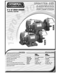
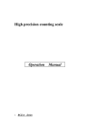
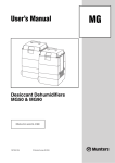
CE
The NCE-AG and
CPE-AG Ranges Range
Commissioning And
Servicing Instructions
WARNING: THIS APPLIANCE MUST BE EARTHED
NCVE-AG/CPE-AG Range Issue 5 April 2003
CONTENTS
Section
Title
Page
1.
2.
3.
4.
5.
6.
7.
8.
2
3
5
6
7
7
8
9.
10.
Introduction
Technical Data
General Requirements
Installation
Air Distribution System
Commissioning & Testing
Servicing
Connections to Powrmatic
External Controls
Fault Finding
Short List of Parts
Tables
Title
Page
1a.
1b.
1c.
1d.
2a.
2b.
3.1
3
3
4
4
4
4
3.2
4.
Dimensions NCE-AG (S.I. Units)
Dimensions NCE-AG (Imperial Units)
Dimensions CPE-AG (S.I. Units)
Dimensions CPE-AG (Imperial Units)
Specifications (S.I. Units)
Specifications (Imperial Units)
Burner Pressures - Natural Gas
Group H - G20
Burner Pressures - Propane - G31
Electrical Loadings
4
4
4
Figure
Title
Page
1.
2.
Honeywell V4400C
Honeywell L4064N
8
10
1
10
11
12
1. INTRODUCTION
The Powrmatic NCE-AG and CPE-AG ranges of gas fired
open flue, fanned circulation air heaters cover a heat output
range of 29.3 kW (100000 Btu/h) to 88.0 kW (300000 Btu/h)
and are intended primarily for heating commercial or industry
premises. They are certified for use on Natural Gas, Group H
- G20 and Propane - G31.
The heaters are for floor mounting only and are available in UF
and UD variants. (U - Upright; F - Freeblowing; D - Ducted).
NCE-AG and CPE-AG heaters have a centrifugal fan assembly
fitted upstream of the combustion chamber / heat exchanger
assembly to circulate the air being heated.
Heaters are fitted as standard with a single venturi inshot
atmospheric gas burner and permanent pilot together with a
multifunctional gas control.
Options include Deep V filters, proportional air dampers and
inlet and outlet duct spigots.
Each air heater must be connected to a open flue system only.
Gas Safety (Installation & Use) Regulations 1994
It is law that all gas appliances are installed, adjusted and, if
necessary, converted by qualified persons* in accordance with
the above regulations. Failure to install appliances correctly
can lead to prosecution. It is in your own interests and that of
safety to ensure that the law is complied with.
* e.g. Corgi Registered
2
2 Technical Data
2.1 Dimensions
D
F
E
G
C
NCE-AG 100UF SHOWN
J
K
H
B
FRONT
VIEW
A
D
F
SIDE
VIEW
E
G
CE-AG 300UF SHOWN
C
J
K
A
H
B
FRONT
VIEW
Table 1a. Dimensions NCE-AG (S.I. Units)
A
B
C
D
E
F
G
H
J
K
NCE-AG 100
1340
631
1820
277
250
200
2629
527
533
705
NCE-AG 200
1390
730
2077
301
280
200
3182
629
580
756
Table 1b. Dimensions NCE-AG (Imperial Units)
A
B
C
D
E
F
G
H
J
K
NCE-AG 100
52¾
24¾
71¾
11
10
8
103½
20¾
17¾
27¾
NCE-AG 200
57¾
28¾
81¾
11¾
11
8
125¼
24¾
24¾
29¾
3
SIDE
VIEW
Table 1c. Dimensions CPE-AG (S.I. Units)
A
B
C
D
E
F
G
H
J
K
CPE-AG 100
809
631
1820
277
250
200
2629
527
533
705
CPE-AG 200
855
730
2077
301
280
200
3182
629
580
756
CPE-AG 300
1060
908
2356
329
320
250
3455
806
525
959
Table 1d. Dimensions CPE-AG (Imperial Units)
A
B
C
D
E
F
G
H
J
K
CPE-AG 100
31¾
24¾
71¾
11
10
8
103½
20¾
21
27¾
CPE-AG 200
33¾
28¾
81¾
11¾
11
8
125¼
24¾
23
29¾
CPE-AG 300
41¾
35¾
92¾
13
12½
10
136
31¾
20¾
37¾
Table 2a - Specifications (S.I. Units)
HIGH FIRE
MODEL
INPUT
(Nett)
OUTPUT
MAXIMUM DUCT
RESISTANCE
AIR
VOLUME
kw
Standard
m³/s
L.H.P.
FAN MOTOR
Standard
pa
WEIGHT
L.H.P.
GAS
CONNECTION
SIZE
kg
kw
NCE/CPE-AG 100
33.5
29.3
0.7340
100
N/A
0.335
N/A
NCE/CPE-AG 200
68.9
58.6
1.5575
250
N/A
1.5
N/A
CPE-AG 300
103.5
88.0
2.0766
150
N/A
2.2
N/A
167
R¾
296
381
Table 2b - Specifications (Imperial Units)
HIGH FIRE
MODEL
INPUT
(Gross)
OUTPUT
MAXIMUM DUCT
RESISTANCE
AIR
VOLUME
Btu/h
Standard
ft³/m
L.H.P.
FAN MOTOR
Standard
in wg
WEIGHT
L.H.P.
GAS
CONNECTION
SIZE
lb
hp
NCE/CPE-AG 100
126984
100000
1555
0.40
N/A
0.47
N/A
NCE/CPE-AG 200
261438
200000
3300
1.00
N/A
2.0
N/A
CPE-AG 300
392157
300000
4400
0.60
N/A
3.0
N/A
367
¾"BSP
651
840
Table 3.1 Burner Pressures - Natural Gas - Group H - G20 - Net CV (Hi) = 34.02MJ/m³
Injector Siz e
Pilot R ate
Type
mm
in
A1
5.0
0.196
N C E/C PE-AG 200
A2
7.00
0.275
C PE-AG 300
A3
8.5
0.334
N C E/C PE-AG 100
kW
0.1
Main B urner
Pressure
Gas R ate
mbar
in w g
m³/h
ft³/h
13.0
5.2
3.54
125.0
11.0
4.4
7.29
257.4
11.3
4.5
10.81
381.7
Table 3.2 Burner Pressures - Propane - G31 - Net CV (Hi) = 88.00MJ/m³
Type
NCE/CPE-AG 100
A1
Injector Siz e Pilot Rate
mm
in
3.2
0.125
kW
NCE/CPE-AG 200
A2
4.6
0.181
CPE-AG 300
A3
5.61
0.220
Table 4
0.1
Main Burner
Pressure
mbar
in w g
m³/h
ft³/h
23.3
1.37
48.4
9.3
25.3
10.1
2.82
99.6
24.8
10.0
4.18
147.6
Electrical Loadings
Standard
MOTOR
MODEL
ph
R.P.M.
NCE/CPE-AG 100
NCE/CPE-AG 200
CPE-AG 300
Gas Rate
1
3
1000
Larger Horsepower Motor
PLATE
AMPS
(A)
START
AMPS
(A)
FUSE MOTOR
RUN AMPS
RATING
(A)
(A)
R.P.M.
2.6
5.6
2.9
5
7.0
18.0
8.1
10
6.7
14.0
6.0
7
PLATE
AMPS
(A)
START
AMPS
(A)
N/A
4
RUN
AMPS
(A)
FUSE
RATING
(A)
3.3.2 Meters
3. General Requirements
A gas meter is connected to the service pipe by the local gas
undertaking or a local gas undertaking contractor. An existing
meter should be checked, preferably by the gas undertaking, to
ensure that the meter is adequate to deal with the total rate of
gas supply required.
3.1 Related Documents
The installation of the air heater(s) must be in accordance with
the rules in force and the relevant requirements of the Gas
Safety Regulations, Building Regulations and the I.E.E.
Regulations for Electrical Installations.
It should be in accordance also with any relevant requirements
of the local gas region, local authority and fire authority and
the relevant recommendations of the following documents.
3.3.3. Installation Pipes
Installation pipes should be fitted in accordance with
IM/16:1988. Pipework from the meter to the air heater must be
of adequate size. Do not use pipes of a smaller size than the
inlet gas connection of the heater. The complete installation
must be tested for soundness as described in the above Code.
The complete installation must be tested for soundness as
described in BS 6230.
British Gas Plc Publications
IM/11 : 1989 Flues for Commercial and Industrial Gas Fired
Boilers and Air Heaters
IM/16 : 1988 Guidance notes for the installation of gas
pipework, boosters and compressors in Customer’s premises
(excluding domestic installation of 25mm and below).
3.3.4. Boosted Supplies
Where it is necessary to employ a gas pressure booster the
controls must include a low pressure cut off switch at the
booster inlet. The local gas undertaking must be consulted
before a gas pressure booster is fitted. The maximum inlet
pressure is 60mb.
British Standards Code of Practice
BS 5588 Fire precautions in the design and construction of
buildings.
Part 2 : 1985 Code of Practice for Shops
Part 3 : 1983 Code of Practice for Office Buildings
BS 6230: 1991 Installation of Gas Fired Forced Convection
Air Heaters for Commercial and Industrial Space Heating.
3.4 Flue System
Detailed recommendations for fluing are given in BS 5440,
Part 1 (Flues) and IM/11.
The air heater must be connected to an open flue system. The
cross sectional area of the flue serving the appliance must be
not less than the area of the flue outlet of the draught diverter
flue socket.
Materials used for the flue system should be mechanically
robust, resistant to internal and external corrosion,
noncombustible and durable under the conditions to which
they are likely to be subjected.
Prevention of condensation within the flue should be an
important factor in the design of the flue system. In order to
minimise condensation the use of double walled flue pipe or
insulation is recommended. If double walled flue pipe is used
it should be of an acceptable type.
Where condensation in the flue is unavoidable provision
should be made for condensation to flow freely to a point at
which it can be released, preferably into a gully. The
condensation pipe from the flue to the disposal point should be
of non-corrodible material of not less than 22mm (1/2") size.
Facilities should be made for disconnecting the flue pipe(s)
from the air heater(s) for inspection and servicing purposes.
Bends with removable covers should be fitted for inspection
and cleaning purposes where considered appropriate.
The flue should terminate in a freely exposed position and must
be so situated as to prevent the products of combustion entering
any opening in a building in such concentration as to be
prejudicial to health or a nuisance.
An approved terminal must be fitted.
Those appliances having an input rating not exceeding 60kW
viz. NCE-AG 100 and CPE-AG 100 must be installed in
accordance with the relevant recommendations of the following
documents.
BS 5440 Flues and Air Supply for gas appliances of rated input
not exceeding 60kW (1st and 2nd family gases).
Part 1 - Flues, Part 2 - Air Supply
For NCE-AG 100 and CPE-AG 100 units reference should also
be made to BS 5864. Code of Practice for installation of gasfired ducted-air heaters of rated input not exceeding 60kW.
3.2 Location
The location chosen for the air heater must permit the provision
of a satisfactory flue system and an adequate air supply. The
location must also provide adequate space for servicing and air
circulation around the air heater.
The heater(s) must not be installed in conditions for which it
is not specifically designed e.g. where the atmospheric is
corrosive or salty and where high wind speeds may affect
burner operation, and they are not suitable for outdoor use.
Where the location of the air heater is such that it might suffer
external mechanical damage e.g. from overhead cranes, fork
lift trucks, it must be suitably protected.
NCE-AG and CPE-AG units are designed to operate in a
maximum ambient temperature of 25 °C.
3.3 Gas Supply
3.5 Air Supply
In buildings having a design air change rate of less than
0.5 /h, and where NCE-AG and CPE-AG heaters are to be
installed in heated spaces having a volume less than 4.7 m3 /
kW of total rated heat input grilles shall be provided at low
level as follows:(1)
for heaters of heat input less than 60 kW, the
3.3.1 Service Pipes
The local gas undertaking should be consulted at the installation
planning stage in order to establish the availability of an
adequate supply of gas. An existing service pipe must not be
used without prior consultation with the local gas undertaking.
5
(2)
total minimum free area shall not be less than
4.5 cm2 per kilowatt of rated heat input.
for heaters of heat input 60 kW or more, the
total minimum free area shall not be less than
270cm2 plus 2.25 cm2 per kilowatt in excess
of 60 kW rated heat input.
fully ducted, in to and out of the plant room to avoid interference
with the operation of the burner and flue by the air circulation
fan.
The openings in the structure of the plant room through which
the ducting passes must be fire stopped.
Care must be taken to ensure that return-air intakes are kept
clear of sources of smells and fumes, and in special
circumstances where there is any possibility of pollution of the
air by dust, shavings etc., precautions must be taken by
carefully positioning return air intakes and by the provision of
screens to prevent contamination.
In addition, where there is a risk of combustible material being
placed close to the warm air outlets, suitable barrier rails
should be provided to prevent any combustible material being
within 900mm (3ft) of the outlets.
Where the air heater(s) is to be installed in a plant room the
plant room housing it must have permanent air vents
communicating directly with the outside air, at high level and
at low level. Where communication with the outside air is
possible only by means of high level air vents, ducting down to
floor level for the lower vents should be used.
All air vents should have negligible resistance and must not be
sited in any position where they are likely to be easily blocked
or flooded or in any position adjacent to an extraction system
which is carrying flammable vapour.
Grilles or louvres should be so designed that high velocity air
streams do not occur within the plant room.
3.7 Electrical Supply
Wiring external to the air heater must be installed in accordance
with the I.E.E. Regulations for Electrical Installations and any
local regulations which apply. Wiring should be completed in
flexible conduit.
Heaters NCE-AG and CPE-AG 100 - 200 are supplied by 230V
- 1ph, 50Hz,the CPE-AG 300 by 400V - 3N, 50Hz. The method
of connection to the main electricity supply must facilitate the
complete electrical isolation of the air heater(s) and the supply
should serve only the air heater(s).
The isolator must have a contact separation of at least 3mm in
all poles. The method of connection should be provided
adjacent to the air heater(s) in a readily accessible position.
See the accompanying wiring diagram for the heater electrical
connections
The basic minimum effective area requirements of the air vents
are as follows:
(a)
Low Level (inlet)
(1)
for heaters of total rated heat input less than 60 kW:
9 cm2 per kilowatt of rated heat input
(2) for heaters of total rated heat input 60 kW or more:
540 cm2 plus 4.5 cm2 per kilowatt in excess of
60 kW total rated input.
(b)
High Level (outlet)
(1)
for heaters of total rated heat input less than 60 kW:
4.5 cm 2 per kilowatt of rated heat input;
(2)
for heaters of total rated heat input 60 kW or more:
270 cm2 plus 2.25 cm2 per kilowatt in excess of
60kW total rated input.
4. Installation of Air Heater(s)
4.1 General
3.6 Air Distribution System
Before installation, check that the local distribution
conditions, nature of gas and pressure, and adjustment of
the appliance are compatible.
The following notes are of particular importance.
For free-blowing units it must be taken into account that the
buoyancy of the heated air leaving the heater and air patterns
within the space being heated will modify the air throw pattern
achieved. In buildings having a low heat loss where single
units are required to cover a large floor area and in buildings
with high roof or ceiling heights Calecon thermal economiser
units should be fitted to ensure even heat distribution and
minimise stratification respectively. Care should be taken to
avoid impeding the air throw with racking, partitions, plant or
machinery etc.
The air heater must be installed in accordance with the rules
in force and the relevant requirements of any fire regulations
or insurance company’s requirements appertaining to the area
in which the heater is located, particularly where special risks
are involved such as areas where petrol vehicles are housed,
where cellulose spraying is carried out, in wood working
departments etc. NCE AG and CPE AG heaters must not be
installed in areas subjected to negative pressures due to extract
systems.
The following minimum clearances for installation and
servicing must be observed.
To the front
The depth of the heater
To the rear
1.0m (3.3ft)
To at least one side
1.0m (3.3ft)
Above the heater
1.00m (3.3ft)
For ducted units all delivery and return air ducts, including air
filters, jointing and any insulation or lining must be constructed
entirely of materials which will not contribute to a fire, are of
adequate strength and dimensionally stable for the maximum
internal and external temperatures to which they are to be
exposed during commissioning and normal operation. In the
selection of materials account must be taken of the working
environment and the air temperatures which will result when
the overheat limit thermostat is being commissioned. Where
inter-joist spaces are used as duct routes they should be suitably
lined with a fire-resisting material.
A full and unobstructed return air path to the air heater(s) must
be provided.
If the air heater(s) is installed in a plant room the return air
intake(s) and the warm air outlet(s) from the heater(s) must be
Any combustible material adjacent to the air heater and the flue
system must be so placed or shielded as to ensure that its
temperature does not exceed 65 °C (150 °F)
IMPORTANT:
1.
No air heater shall be installed where there is a
foreseeable risk of flammable particles, gases vapours or
corrosion inducing gases or vapours being drawn into either
6
the heated air stream or the air for combustion. In certain
situations where only airborne particles are present it may
suffice to fit filters on the air inlet ducts of the heater. Advice
in these instances may be obtained from Powrmatic Ltd.
5. Air Distribution System
5.1 General
NCE-AG ###UD and CPE-AG ###UD models are designed
for use with duct work to more precisely define the point of air
delivery, and /or provide ducted return air or ducted fresh air
inlet. All ducting must be independently supported of the air
heater. Joints and seams of supply ducts and fittings must be
securely fastened and made airtight.
4.2 Fitting the Air Heater
The heaters must be installed on a level noncombustible
surface.
If noise levels are of particular importance the heater should be
insulated from the structure of the building by installing it on
suitable anti-vibration mountings. In all such cases it is
essential that all gas, duct, electrical and flue connections to
the heater are made with flexible connections to maintain
continuity of connection. In the case of the flue connection
single wall stainless steel flue is deemed to flex sufficiently to
meet the requirements.
5.2 Noise Reduction
If deemed necessary consideration should be given to mounting
the heater on resilient pads, or equivalent, to minimise transfer
of noise and vibration to the structure of the building.
It is recommended that ducting should be connected to the
heater spigots via an airtight flexible coupling of noncombustible
material. Before fitting coupling it must be ensured that a
maximum clearance of 13mm (1/2") will be maintained between
the ends of the ducting and the heater spigots.
If required sound attenuators may be fitted in inlet and outlet
ducts to reduce airborne fan noise. Materials used in outlet
sound attenuators must be capable of withstanding 100 °C air
temperature without any deterioration.
4.3 Connection of Air Heater(s) to Flue
System
A single wall 90° Bend and draught diverter assembly is
supplied with each heater and must be fitted to the flue outlet
socket on the heater. The flue system connects directly on to the
draught diverter and must have a minimum length of 2.0m.
For flue sizes refer to Tables 1a and 1b Page 4 . Horizontal
runs of flue are not permitted. If necessary a single offset using
two 45° bends can be included to avoid obstructions.
5.3 Room Thermostat Siting
The room thermostat should be fitted at a point which will be
generally representative of the heated area as far as temperature
is concerned. Draughty areas, areas subjected to direct heat e.g.
from the sun, and areas where the air movement is relatively
stagnant e.g. in recesses, are all positions to be avoided for
siting the thermostat.
The thermostat should be mounted about 1.5m (5ft) from the
floor.
Any room thermostat, frost thermostat, time clock etc. must be
suitable for switching 230V, 5A and must be of the 'snap
action' type to minimise contact bounce.
For electrical connections of external controls see the
accompanying wiring diagram.
4.4 Condensate Drainage
The design of the flue system should minimise the formation
of condensation, however when this is envisaged to be a
problem provision should be made for condensation to flow to
a joint where it can be drained, preferably into a gully.
4.5 Gas Connection
A servicing valve and downstream union must be fitted at the
inlet to the air heater gas controls assembly to facilitate
servicing . The gas supply to the air heater must be completed
in solid pipework and be adequately supported.
WARNING: When completing the final gas connection to the
heater do not place undue strain on the gas pipework of the
heater.
6. Commissioning & Testing
6.1 Electrical Installation
4.6 Electrical Connections
Checks to ensure electrical safety must be carried out by a
qualified person.
All units are fully pre-wired and only require final connections
for the incoming mains supply and completion of the control
circuit (230V) via a room thermostat, time clock etc. The
electrical supply must be run to a point adjacent to the heater
and be suitably terminated to provide an isolation point that
will prevent remote activation of the unit during servicing. The
heater electrical panel is located behind the front panel and
cable entry points are provided in the adjacent heater framework.
Reference must be made to Table 4 (Page 6) to ascertain the
electrical loading of the air heater(s) being installed so that
cables of adequate cross-sectional area to safely carry that load
are used for the electrical installation. The length of the
conductors between the cord anchorage and the terminals must
be such that the current carrying conductors become taut
before the earth conductor if the cable or cord slips out of the
cord anchorage. All external controls must be of an approved
type.
See the wiring diagram accompanying these instructions.
6.2 Gas Installation
The whole of the gas installation, including the meter, should
be inspected and tested for soundness and purged in accordance
with the recommendations of IM/16:1988.
6.3 Air Distribution System
The system should be checked to ensure that the installation
work has been carried out in accordance with the design
requirements.
Particular attention should be given to the correct arrangement
of delivery ducts and registers, return air ducts and grills and
general adequacy of return air paths.
For NCE-AG ###UD and CPE-AG ###UD heaters ensure that
the total duct system resistance does not exceed the available
air pressure of the equipment supplied refer to Table 2a & 2b
(Page5). If the duct system resistance is less than the available
7
air pressure of the equipment supplied additional resistance
must be introduced e.g. by adjustment of duct outlet nozzles
and balancing of the duct system.
6. Once the pilot has been established, continue pressing the
white start button for approximately 20 seconds and then
slowly release. The pilot should remain alight.
WARNING: Should the pilot be extinguished at any time,
either intentionally or unintentionally, push in and release
the red OFF button (Fig.1 - 2) and wait 3 minutes before
attempting to relight the gas, then repeat steps 3-4 above.
7. Switch on the electricity supply at the isolator and the main
burner will light.
8. SHUT OFF
To interrupt all gas flow through the multifunctional control
press the red OFF button. After waiting 3 minutes the appliance may be relit by following the previous instructions.
6.4 Checks before lighting the Air Heater
The following preliminary checks should be made before
lighting the heater(s)
a) Ensure that the ELECTRICAL supply to the heater is
switched OFF.
b) Check that all warm air delivery outlets are open.
c) Check that the thermostat is set at MAX.
d) Check that the clock control is set to an ON period.
e) Check that any other controls are calling for heat.
f) Ensure that the Summer/Winter switch is in the Winter
position.
g) Check that the overheat reset button has not operated.
6.6 Adjustments
6.6.1 Burner Gas Pressure
6.5 Lighting the Air Heater
This is set for the required heat input before despatch. Pressures should be checked in the following manner.
WARNING: The multifunctional gas control(s) is operated by
230 volts.
NOTES:
1. When attempting to light the pilots at any time ensure that
the mains electricity supply is switched off.
2. On initial lighting of the heater(s), it may take some time to
purge the internal pipework of air.
IMPORTANT:
The internal pipework of the appliance has been tested for
soundness before leaving the factory. After establishing the
pilot(s) and with the main burners alight test round the gas
inlet connection using a leak detection fluid.
1. Set external controls to ensure that the main burner is off.
Connect a pressure gauge to the outlet pressure testpoint on the
multifunctional control.
2. Set external controls so as to turn on the main burner.
Compare the measured burner gas pressure to that stated in
Section 2.
3. If necessary adjust the burner gas pressure by turning the
regulator screw (Fig 1-3) anticlockwise to decrease the pressure, or clockwise to increase the pressure.
4. In addition it is advisable to check the gas rate using the gas
meter dial pointer. Ensure that no other appliances supplied
through the meter are in operation.
5. Turn off the main burner by turning the room thermostat to
MIN or the time clock to OFF and disconnect the pressure
gauge and replace the sealing screw. Turn on the main burner
by resetting the external controls and test for gas soundness
around pressure test joint using a leak detection fluid.
1. Turn on the gas service valve
2. Fully depress the white start button of the multifunctional
control (Fig 1 - 1)
3. Light the pilot flame by pressing the piezo unit button,
located on the heater frame at the right hand side, several times
(Fig 1 - 3) The pilot flame may be viewed through the rear of
the unit.
5. Ensure that the pilot flame fully envelopes 9-12mm of the
thermocouple tip and, if necessary adjust the pilot regulating
screw.
6.6.2 Down Draught Diverter
1. Check that there is no spillage of products of combustion
from the air heater down draught diverter by carrying out a
spillage test, as detailed in BS 5440 Part 1.
2
1
3
Fig. 1 - Honeywell V4400C
1.
2.
3.
4.
5.
6.
7.
8.
9.
10.
START Button (White).
OFF Button (Red).
Governor adjustment cover screw.
Pilot flow adjustment screw.
Thermocouple connection point.
Interrupted thermocouple lead connection to limit
thermostat.
Interrupted thermocouple lead connection from
limit thermostat.
Pilot tube connection point.
Electrical connections for main valve operator.
Earth connection.
10
5
8
6
8
7
4
9
6.6.3 Air Heater Controls
3. Inspect pilot burner, thermocouples and electrode, making
sure that they are in a sound and clean condition.
In particular check that the ignition electrode is clean, undamaged and straight. Check that the spark gap is 2.5-3.5mm.
Clean the pilot injector, do not broach out with wire.
4. Reassemble the pilot and refit to the burner assembly.
Ensure that the thermocouple nut at the multifunctional control is secure, but not over tightened. Tighten by hand, then
tighten by spanner a further 1/6th of a turn. The terminal must
be clean to ensure a good electrical connection.
1. Check that the flame failure device will shut off the gas to
the main burner within 60 seconds by turning off the gas supply
at the gas service valve. A distinct click will be heard when the
thermocouple current is no longer sufficient to hold in the
magnetic unit.
2. Check that the room thermostat and all automatic controls
are operating satisfactorily.
6.6 Handing over the Air Heater
Hand the Users Instructions to the user or purchaser for
retention and instruct in the efficient and safe operation of the
air heater and associated controls.
Adjust the automatic controls to those values required by the
User.
Finally, advise the user or purchaser that, for continued
efficient and safe operation of the air heater, it is important that
servicing is carried out annually.
In the event that the premises are not yet occupied turn off the
gas and electricity supplies and leave instructional literature
adjacent to gas meter.
7.4 Heat Exchanger Cleaning
1. Disconnect the gas supply at the inlet to the gas controls
assembly.
2. Remove the burner as described in 7.2
3. Remove the fan/limit thermostat as described in 7.5.5, the
high limit thermostat as described in 7.5.6 and then remove the
front panel (CPE-AG) or inner panel (NCE-AG) of the heater
to expose the heat exchanger clean out panel. Remove the nuts
securing the panel and remove the panel.
4. Remove the nuts securing the heat exchanger baffles retention strip and remove strip.Withdraw the baffles.
6. Brush through heat exchanger tubes and remove loose
material using a vacuum cleaner. Remove any loose material
from the base of the combustion chamber, working through the
burner port.
7. Reassemble all components in reverse order. Inspect all
gaskets and replace if necessary.
7. Servicing
WARNING: Always switch off and disconnect electricity
supply and close the gas service valve before carrying out any
servicing work or replacement of failed components.
7.1 General
Full maintenance should be undertaken not less than once per
year by a qualified engineer. After any servicing work has been
complete or any component replaced the air heater(s) must be
fully commissioned and tested for soundness as described in
Section 6.
7.4 Fan Assembly
1. Remove the upper and lower side panels on one side of the
heater to gain access to the fan.
2. Inspect the fan blades to see that they are not damaged and
that there is no excessive build up of deposits that could give
rise to an imbalance. If necessary clean the fan blades using a
stiff brush and vacuum cleaner. If it is required to remove the
fan for cleaning refer to section 7.5.4
7.2 Burner Maintenance
1. Ensure that the gas service valve is turned OFF and then
unscrew the union nut situated immediately down stream of it.
2. Disconnect the electrical connections from the multifunctional control.
3. Remove the thermocouple interrupter leads from the multifunctional control by:a) Withdrawing the thermocouple from the interrupter retaining bracket (Fig. 1 - 5 ) and
b) Disconnecting the lead from the valve body.(Fig 1 -7)
4. Remove the lower front panel (CPE-AG) or front panel
(NCE-AG) and disconnect the piezo ignition lead from the
rear of the piezo igniter.
5. Remove the two nuts securing the burner assembly to the
front of the unit and remove the burner complete, from the
front of the air heater, by pulling forwards.
6. Remove any accumalation of deposits from the burner head
and pilot assembly.
7. Reassemble the burner,unless it is required to remove the
pilot assembly (see 7.3), in reverse order to that above. If
necessary replace the burner gasket.
7.5 Replacement of Faulty Components
7.5.1 Multifunctional Control (Honeywell V4400C)
1. Ensure that the gas service valve is turned OFF and then
unscrew the union nut situated immediately down stream of it.
2. Disconnect the electrical connections from the multifunctional control.
3. Remove the thermocouple interrupter leads from the multifunctional control by:a) Withdrawing the thermocouple from the interrupter retaining bracket (Fig. 1 - 5 ) and
b) Disconnecting the lead from the valve body.(Fig 1 -7)
c) Disconnect the pilot tube.
4. Unscrew the multifunctional control from the burner
piprwork.
5. Reassemble in reverse order.
7.3 Pilot Burner Assembly Removal
7.5.2 Pilot Assembly, Thermocouple, Ignition
Electrode.
1. Remove the burner as in 7.2 and release the thermocouple
and pilot gas tube at the multifunctional control
2.Remove the two M5 screws and nuts securing the pilot
assembly to the mounting clip.
1. Remove the burner as described in 7.2
2. Remove the pilot assembly as described in 7.3
3. Exchange the failed component and reassemble in reverse
order.
9
7.5.3 Piezo Unit
5. Ensure that the fan and limit settings are as follows:Fan ON
50°C
Fan OFF
30°C
Limit
90°C
1. Remove the lower front panel (CPE-AG) or front panel
(NCE-AG) and disconnect the piezo ignition lead from the
rear of the piezo igniter.
2. Unscrew the backnut of the piezo unit and withdraw the unit
from the frame.
3. Reassemble in reverse order.
7.5.6 High Limit Thermostat.
1. Release the two screws securing the limit thermostat housing cover and remove cover by pulling forward.
2. Release the thermostat from the front cover, two screws
3. Pull off wiring connectors at the rear of the thermostat.
4.Remove the head base or a top side panel from the heater to
gain access to the heat exchanger and release the thermostat
sensing phial from its holder on top of the heat exchanger and
withdraw thermostat and phial.
5. Reassemble new unit in reverse order refering to the heater
wiring diagram to ensure correct wiring location.
6. Ensure that the setting is as follows:Limit
70°C
7.5.4 Main Air Fan and Motor
1. Disconnect the fan motor electrical leads from the heater
terminal strip (Refer to Wiring Diagram supplied with
theheater)
2. Remove the upper and lower side panels on one side of the
heater.
3. Remove the two set screws, one on each side of the fan
mounting flange, that secure the fan to the fan shroud.
4. Withdraw the fan from the slide rails.
5. Reassemble in reverse order.
Note: On heaters supplied as specials with 3ph motors ensure
that the fan direction of rotation corresponds with the direction
of rotation arrow on the fan guard or case. If necessary reverse
the direction of rotation by interchanging any two of the motor
live leads at the terminal strip in the electrical panel.
8. Connections to Powrmatic External
Controls
8.1 Powrtrol
NCE AG / CPE AG connect to
Terminals
7.5.5 Fan and Limit Thermostat
( Honeywell L4064N )
1. Release the single screw securing the fan and limit thermostat
cover and remove cover by pulling forward.
2. Release wiring from clamp terminals by pushing a small
screwdriver into the clamp release holes adjacent to the
clamps.
1
2
8
9
Fig 2 Honeywell L4064N
NCE AG / CPE AG connect to
Terminals
1
2
8
9
LI
MI T
100 120
CA
DIA DO N
OT U T
LW
IO
R
HE
N S O TA
TE N
ET
- H
TIN
O
G
PO LD
INT
ER
S
Limit Circuit
0
FA N
1
2
5
6
8.2 Eurotrol
Set Point Dial
Fan Circuit
Powrtrol
Terminals
20
8
40 60
Summer /
Winter
Switch
Limit Reset
Limit Circuit
Fan Circuit
Jumper location
3. Remove the 2 screws securing the thermostat to the heater
panel and withdraw thermostat.
4. Reassemble new unit in reverse order refering to the heater
wiring diagram to ensure correct wiring location.
Important:As supplied by the Manufacturer this fan/limit
thermostat is fitted with a brass jumper between the bottom fan
terminal and the bottom limit terminal (situated in the slot
between the two terminals). This MUST be removed, by using
a pair of thin nose pliers, before the replacement thermostat is
installed.
10
Eurotrol
Terminals
CTRL CCT
CTRL CCT
FAN CCT
FAN CCT
9.
Fault Finding
Fault
Cause
Action
Main burner will not light
Electrical
1. Check electrical and gas supplies are ON.
2. Check that pilot is alight.
3. Check controls are ON or calling for heat.
Main burner lights, but goes
out before main fan comes on.
Electrical
1. Unit goes out on high limit a. Check fan thermostat setting - See Section 7.5.5.
b. Faulty fan thermostat - change
c. Check limit thermostat setting - See Section 7.5.5.
d. Faulty limit thermostat - change.
2. Faulty fan assembly - change.
3. (3ph and Ducted Units Only) -fan motor out on thermal overload. - Check
running amps. See table 4.- check duct resistance See Table 5.
Main fan runs continuously
Electrical
1. Summer/Winter switch set to Summer.
2. Fan thermostat set too low - check setting See Section 7.5.5
3. Faulty fan thermostat - change
Main fan fails to run
Electrical
1. Fan motor or capacitor failed - replace.
2. Fan thermostat faulty - replace.
3. Fan contactor failed - replace (3ph units)
11
10. Short List of Parts
Refer to Powrmatic Ltd for the details of any parts not listed here.
ITEM
APPLICATION
PART NUMBER
MFC - Honeywell V4400C 1377
Thermostat - Limit - Landis & Gyr Rak 21-4-2924
Thermostat - Fan / Limit Honeywell L4064N.
Heat Exchanger Cleanout Door Gasket.
Interrupted Thermocouple lead - Honeywell
45002837-002
Interrupted Thermocouple lead - Honeywell
45002837-007
Thermocouple
Piezo Unit - Morgan & Matroc 66156
Pilot Assembly - Johnsons - 27A4G3R c/w
Pilot injector - 7215 - G20
Pilot Injector - 4209 - G31
ALL
ALL
ALL
ALL
142400434
142403595
143000303
170246006
ALL
142402261
ALL
ALL
ALL
142402262
142403002
142436021
ALL (G20)
ALL (G31)
141856010
141854010
12
BSI Registered Firm
FM 414
Ind. & Comm. Air Heaters;
Air Moving Equipment;
Flues & Chimneys; Natural
Smoke & Heat Ventilators;
Powered Supply & Extract
Fans & Systems.
HEATING DIVISION
Winterhay Lane
Ilminster, Somerset TA19 9PQ
Tel: 01460 53535 Fax: 01460 52341
Every effort is made to ensure accuracy at time of going to press. However as part of our policy of continual product improvement, we reserve the right to alter specifications without prior notice.