1
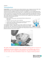
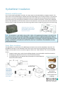
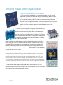
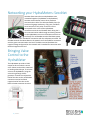
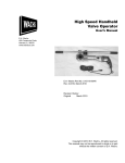
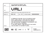
Installation Guide 4/20/2015 1 | P A G E Introduction 4/20/2015 Congratulations... You have selected the most advanced and diverse water management device available. With engineering inspiration, Seco Sys has designed and developed the HydraMeter to be the first fully comprehensive water management device ever conceived. The HydraMeter is an ultra‐intelligent water meter controller that mounts atop many common water meters. In its application, users can have visibility and control of water consumption in a way never obtained before. Like Hydra, the powerful multi‐headed water serpent of Greek mythology, Seco Sys’ HydraMeter has several metering personalities and modes of operation. This unique ability makes it possible for the HydraMeter to tackle nearly any water management task, setting it apart from other available water management devices. Key features are as follows: Advanced flow measurement and processing for flow‐rate, flow‐time and flow‐volume. Independent control of master valves and pumps. Configurable water budget management with automatic alarm response. Direct interface with flow sensor compatible control systems. Internet communication capable. The HydraMeter facilitates a single solution for all water management requirements. The HydraMeter controller is completely scalable and mounts to nearly any AWWA approved water meter, allowing it to easily integrate and manage water for small or large water delivery systems. To take full advantage of the many personalities and features of your HydraMeter, please take the time to review the user manual. This guide is intended to be a general overview, and is NOT a plumbing “How To.” If you are not experienced in water meter installation, or have any doubts as to your abilities, please seek out a qualified installer. If you are doing your own installation, be aware that you are doing so at your own risk and Seco Sys will not be held liable for failures due to improper installation procedures. 2 | P A G E HydraMeter Specifications BASIC METERING FEATURES Acquires flow measurement resolution from AWWA water meters. Measures flow down to .04/gallons per minute with zero drag. Multiple character LCD display to interpret water consumption and alarms. Configurable units of measure (Gallons or Liters) Simultaneous display of flow rate and accumulated volume. OPERATING FEATURES Multi‐mode keypad interface for direct configuration. Manual control keys to Open or Close a connected valve. Rechargeable Lithium Ion Polymer Batter CONTROL FEATURES Control output for electric valve (Motorized or DC Latching type). Configurable limit alert by flow‐time: limits how long a flow event is permitted to run. Configurable limit alert by high flow‐rate: limits the highest flow rate permitted for any event. Configurable limit alert by low flow‐rate: limits the lowest flow rate permitted for any event. Configurable limit alert by flow‐volume: limits the volume of water delivered for any event. Configurable leak rate detection independent of low flow‐rate. Configurable water‐window schedules, up to 4 per day. Flow‐time limits can be set to 16 hours 39 minutes, in one‐second increments. Optional output for booster pump control, activated by user defined flow rate. Pulsed flow output signal to share live flow rate data with compatible equipment. Independent programmable alarm delay time for all limits. Connectivity for networking multiple HydraMeters, up to 19 in cascaded configuration. AVAILABLE OPTIONS Ability to connect to the internet using SecoNet via HydraPod or HydraConnect. Ability to operate in remote locations using solar power from a HydraPod. Ability to share flow data with SCADA and other compatible third party equipment MECHANICAL SPECIFICATION Durable, fade resistant injection molded plastic enclosure with hinged lid Water tight transparent cover with valve control access Liquid tight cord‐grip connection ports Dimensions: 4 1/4W x 3H x 5 1/2D inches /107.95W x 76.2H x 139.7D mm (without meter adapter) Shipping Weight: 12.3 Ounces (without meter adapter) 3 | P A G E ELECTRICAL SPECIFICATIONS Input power: 12 VDC, 50mA MAX Reserve Power: 3.7v Lithium Ion Polymer Battery Output Valve Control: 12 VDC Latching or Continuous Current, 1.5 Amp Max impulse. Output Valve Control: Type ‐ DC Latching or Continuous Current Power ‐ 12 VDC, 1.5 Amp Max Impulse Current Optional Pump Control: Type ‐ Non‐Latching Relay Coil Power ‐ 12 VDC, 50mA Max WARRANTY 3 year limited warranty 4 | P A G E HydraMeter Installation Where to install the meter Prior to securing the HydraMeter controller, the water meter must be plumbed by a competent installer. The water meter can be installed above or below ground level depending on local climate conditions. The preferred alternative is to place the HydraMeter above ground where the water delivery plumbing and electrical power are easily accessed. For below ground installations, the meter should be contained in a meter box as depicted below. If the HydraMeter and an electronic valve are to be housed in a common meter box the box should be at least 16 inches in length for meters up to 9 inches long, and 24 inches in length for meters ups to 16 inches long. These boxes are low cost and readily available from plumbing and landscape outlets or home improvement stores. Water Meter Installation The HydraMeter is a combination of an AWWA approved water meter and the HydraMeter Controller. The HydraMeter Controller can be mounted to most meter service sizes mounts by latching onto the mounting flanges normally used to secure a mechanical register. Refer to the “Table of Meters” for a list of compatible meters. To plumb a water meter, special seals and flange adapters are used establish a leak free connection. The flange type depends on the meter size (see illustration below). The flange fittings must be appropriately spaced apart to accommodate the 5/8 to 1 inch service meter that will be installed. 1 ½ inch and up Face‐to‐face fitting spacing required for a particular size water meter can be determined from Table 1. 5 | P A G E For sizes above 2 inches, use the manufacturers’ dimensional specifications and recommended meter couplings. Bringing Power to the HydraMeter 3 Ways to bring power to a HydraMeter 1. If you are using the HydraMeter as a stand‐alone product, you will use the supplied wall mount 12 Volt DC at 300 milliamps power supply. Make sure that the power outlet you use is appropriate to the environment and complies with any local building or safety codes. Minimally we recommend a weatherproof outlet with a built‐in high‐sensitivity GFCI. Connect the red positive wire from the power supply to a red SecoNet terminal on the HydraMeter. Connect the black negative wire from the power supply to a black SecoNet terminal on the HydraMeter. 2. Another way to bring power (along with communications) to the HydraMeter is to connect it to an iDrop. iDrops are installed into conventional electrical junction boxes. Since these boxes come in a variety installation and service types, the box that best suits the environment should be used. For example, if an iDrop is to be installed into an existing wall, a conventional wall type box is suggested. If the iDrop is to be installed outdoors, a weather‐ proof box is appropriate. Power is brought into the iDrop using a Seco Sys provided AC power supply with an output rating of 12 volts DC. On the back of the iDrop are connectors with colored terminals similar to those found on the HydraMeter. Connect the red positive wire from the power supply to the right hand red terminal on the iDrop connector. The black negative wire from the power supply is to be connected to the right hand black terminal. The green will be empty. Along with distributing power for HydraMeters, special function iDrops provide a docking station for specialized Seco Sys water management devices. These iDrops can provide interface to third part water management devices such as irrigation controllers and supervisory control and data acquisition (SCADA) systems. A special function iDrop will have connectors labeled “Pulse Flow” and “RS 232” are reserved for interface with compatible third party equipment. This feature permits the sharing of relevant information with other devices or systems such as irrigation controllers or supervisory control and data acquisition devices. 3. Finally, power can be supplied to the HydraMeter by connecting it to a solar powered HydraPod. The wiring is similarly color coded, and more specific instructions can be found in the HydraPod installation manual. 6 | P A G E Networking your HydraMeters: SecoNet SecoNet allows more than one HydraMeter to be networked together (HydraMeter‐to‐HydraMeter). SecoNet communication uses a three conductor communication cable. The cable specified by Seco Sys has three 24 gauge conductors; red, green, and black wires housed in a PVC jacket. These wire colors correspond to the colors of the HydraMeter connection terminals and SecoNet labels. Bring the 3 wire communication cable through one black grommet on the HydraMeter to one set of SecoNet terminals on the iDrop. The red SecoNet terminal distributes power on the network and is intended for connection with the red power wire lead. The green SecoNet terminal distributes data on the network and is intended for connection with the green communication wire lead. The black terminal distributes the negative voltage and ground on the network and is intended for connection with the black negative wire lead. Bringing Valve Control to the HydraMeter The HydraMeter provides 12 VDC output to drive an electric control valve. Valves can be either motorized or latching solenoid type. To wire the valve to the HydraMeter, bring the valve wiring through a black grommet. Connect the red positive lead of the valve to the red ValveNet connector terminal and black negative lead of the valve to the black ValveNet connector terminal. 7 | P A G E