1
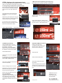
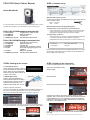
)4&LR Vision Colour Sensor
STEP 1: General setup
Quick Start Guide
It is recommended to read this quick start guide f irst and ref er to other
included documentation f or f urther details or when ref erenced to.
FQ-CLR-V1P 3M Package content (part list)
1 x FQ-S15050)
Single function vision sensor
1 x FQ-WN003-E
Ethernet cable 3m
1 x FQ-WD003-E
I/O cable 3m
1 x AFBN004_FQ-CLR )4&/54uick Start Guide
FQ-CLR-V32P 3M Package content (part list)
A) Connect the sensor to power
Connect the I/O cable to the FQ2-CLR colour vision sensor and connect to a power source:
- brown: +24 VDC
- blue: 0 VDC
B) Connect the sensor to the programming tool
1) Programming via Touch Finder–programming device
- connect the sensor to the touch finder using the ethernet cable
- power up the touch finder using the battery or the AC power
supply(refer to separate instruction sheets for details)
2) Programming via PC tool
- connect the sensor to your PC (manual IP address assingment)
or a DHCP server (automatic IP address assignment)
- download the PC tool from www.omron-cxone.com/vision_sys
1 x FQ-S25050F0ulti function vision sensor
1 x FQ-WN003-E
Ethernet cable 3m
1 x FQ-WD003-E
I/O cable 3m
1 x FQ-D31 7ouch Finder –programing device
1 x FQ-AC4
AC power supply (plug type C) for
FQ-D31
1 x FQ-BAT1
Battery for FQ2-D31
1 x AFBN004_FQ2-CLR FQ-CLR Quick Start Guide
Refer to Z326 FQ2 User Manual for detailed explanations on connecting the sensor and assigning the IP address. Please download from
www.industrial.omron.eu/fq2-clr
STEP 2: Setting up the sensor
STEP 3: Setting up the inspection
1.Connecting the sensor
Power up the Touch Finder or start the
PC tool and follow the instructions. The
sensor should connect automatically
after a few seconds after powering up
or press ‘auto connect’.
2. Adjusting the image
STEP a): mechanical adjustment
Place a GOOD sample of the object
to be inspected in front of the sensor.
Adjust the camera distance and
position to the desired field of vision.
License No.:
Product Key:
1609-2389-9941-6099
8121306
Confirm the settings and return to the main menu.
Select from the INSPECT field
INSPECTION.
Select ADD item.
Select COLOR DATA from the list
STEP b): brightness adjustment
Select from the IMAGE field CAMERA SETUP and BRIGHTNESS from
the menu on the upper right hand side. If you do not see the below
menu, select SENSOR SETTINGS from the bottom right menu.
To select the inspection area select TEACH, adjust the green
inspection area, confirm with the OK and TEACH button and return
to SETTINGS screen. For re-adjusting the inspection area after
confirming or teaching select INSP. REGION from the upper right
hand menu in the TEACH screen.
If the picture brightness is too dark or too light, use the AUTO button or
the manual adjustment until the object and the colour are clearly visible.
To set up the judgement criteria or to transmit the RGB values see
next page.
Note:
Other inspection region shapes than rectangular can be defined. Refer to Z326 FQ2 Users Manual.
STEP 4: Setting up the judgement criteria
To set up the judgement criteria whether a product is considered suitable
(OK) or not good (NG), several options are available.
2. Manual tolerance adjustment (good sample only)
After setting up the inspection area select JUDGMENT.
1.Teaching with good (OK) and not good (NG) sample
Place the good (OK) sample in front of the
sensor and select AUTO ADJUSTMENT
from the menu on the upper right hand
side.
Press OK Teach for the good sample
several Times or teach several good
samples
Replace the good sample by the not good
sample and press NG Teach several times
or teach several not good samples.
To verify the success of the teaching,
Return to main menu and select from the
TEST field CONTINUOUS TEST.
Select Graphics+Details
Select the upper value and enter the accepted
tolerance level.
A high number ensures a stable process.
Setting a low number may be useful for detecting minor errors e.g. label displacements.
Test results of good and not good sample
To switch into normal operation return to main menu and select RUN
3. RGB value processing
Using the RGB values is recommended when using e.g. the ‚worst
OK sample‘ or the ‚best
NG sample‘ to set the thresholds.
Return to main menu and select from
the INSPECT field CALCULATION.
OPTIONAL: RGB out via ethernet
Return to the main menu.
To assign the RGB values to the
ethernet output, select from the
IN/OUT field I/O SETTING.
Select EXPRESSION
Select Ethernet
Select the first expression and select
MODIFY.
It is optional but recommended to first
rename this and the following expressions to RED, GREEN, BLUE
Select OUTPUT DATA SET
After selecting MODIFY select DATA
and COLOUR DATA.
Select the first data and select
SETTINGS.
Select R average AR for red colour.
Repeat this for the second and third
expression with green (G average
AG) and blue (B average AB)
Select COLOR DATA and Select R
average AR for red.Repeat this for
the 2nd and 3rd data with green and
blue.
Return to the calculation screen and
select JUDGEMENT.
The actual RGB values are
displayed. For each value upper and
lower thresholds can be entered
numerically. (adjustment via slider
not possible as default values are too
large)
OMRON Europe B.V.
Wegalaan 67 – 69
2132 JD Hoofddorp
The Netherlands
AFBN0049_FQ-2CLR
Tel.: +31 235681-300
Fax: +31 235681-388
www.industrial.omron.eu