1
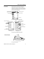
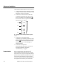
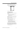
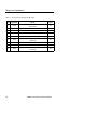
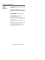
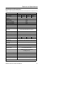
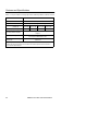
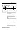
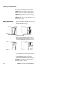
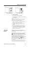
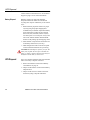
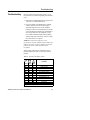
ONePlus UPS
ONePlus Series UPS
User Instruction Manual
IMPORTANT SAFETY INSTRUCTIONS
SAVE THESE INSTRUCTIONS.
Please read and save these instructions. This manual contains important
instructions for the ONePlus UPS. Follow these instructions during the
unpacking, installation and maintenance of the ONePlus UPS. If you have a
problem with the unit, please refer to this manual before calling ONEAC
Technical Services.
Licenses and Trademarks
ONEAC, Virtual Kelvin Ground and MopUPS are all registered trademarks and
ONePlus is a trademark of ONEAC Corporation. All other trademarks, product
and corporate names are the property of their respective owners.
ONEAC USA
27944 North Bradley Road
Libertyville, IL 60048-9700
USA
ONEAC EUROPE
George Curl Way
Southampton, Hampshire SO18 2RY
United Kingdom
Telephone: (847) 816-6000
Toll Free: (800) 327-8801
Facsimile: (847) 680-5124
Telephone: +44 (0) 2380 610311
Facsimile: +44 (0) 2380 612039
Entire contents copyright © 2004 ONEAC Corporation. All rights reserved. Reproduction in whole or
in part without permission is prohibited. All information subject to change without notice.
913-577 Rev. -
ONePlus UPS User Instruction Manual
12/04
Introduction ....................................................................................... 1
Registering Your ONEAC UPS ............................................................. 1
Technical Support ............................................................................... 1
FCC Compliance ................................................................................ 2
Safety (English) ................................................................................... 3
Sicherheitshinweise (Deutsch) ............................................................. 4
Mesures de sécurité (Français) ............................................................ 5
Seguridad (Español) ............................................................................ 6
Theory of Operation ........................................................................... 7
AC Power Mode .......................................................................... 7
Battery Backup Mode ................................................................... 7
Output Overload Protection ......................................................... 8
Setup and Installation ......................................................................... 9
Installation ................................................................................... 9
Long Term Storage ...................................................................... 9
Ventilation ................................................................................. 10
Grounding the Unit .................................................................... 10
Connections .............................................................................. 11
ONePlus Front Panel ................................................................... 12
Power Switch ............................................................................. 13
Self-Test ..................................................................................... 14
Indicators and Alarms ................................................................ 14
Communications ........................................................................ 16
Features and Specifications ............................................................... 19
Physical and Electrical Specifications ........................................... 20
Specifications and Characteristics ............................................... 21
Typical Runtimes ........................................................................ 23
Battery Considerations ..................................................................... 23
Battery Replacement Procedures ................................................ 24
Testing New Batteries ................................................................ 25
Battery Disposal ......................................................................... 26
UPS Disposal .................................................................................... 26
Troubleshooting ............................................................................... 27
Warranty .......................................................................................... 30
Batteries .................................................................................... 30
Limitations of Warranty .............................................................. 30
Exclusive Remedies ..................................................................... 30
Return Procedure ....................................................................... 30
ONePlus UPS User Instruction Manual
i
Introduction
Introduction
Thank you for selecting this uninterruptible power
supply (UPS). ONEAC’s ONePlus UPS offers the
most reliable protection from the harmful effects of
electrical line disturbances for your computing and
communications equipment. ONEAC’s ISO 9001
certification represents our commitment to building
world-class products. We take pride in every unit that
leaves our manufacturing facility.
RegisteringYour
ONEAC UPS
To ensure that your ONePlus Series UPS model and
serial number are registered, complete and mail the
enclosed postage-paid warranty card or go on line at
www.oneac.com.
Technical
Support
ONEAC offers 24-hour technical support. To contact
ONEAC Technical Services:
• North America: (847) 816-6000, option 3
or toll free (800) 327-8801, option 3.
• Europe: +44 (0) 1235 861962
• email: [email protected].
In North America, all calls received before 7 a.m.
and after 5 p.m. CST are forwarded to a cell phone.
Between 5 p.m. and 10 p.m. CST, ONEAC Technical
Services Representatives will return your call within
one half hour (between 5 p.m. and 10 p.m.). Except
for emergencies, calls received between 10 p.m. and
7 a.m. CST will be returned during normal business
hours.
Please check with ONEAC Technical Services
before attempting to repair or return any ONEAC
product. If an ONEAC UPS needs repair or
replacement, ONEAC Technical Services will issue
a Return Material Authorization (RMA) number
along with instructions on how to return the UPS.
ONePlus UPS User Instruction Manual
1
FCC Compliance
FCC
Compliance
ATTENTION: Changes or modifications to this unit
not expressly approved by the party responsible or in
FCC compliance could void the user’s authority to
operate the equipment.
This equipment was tested and complies with the
limits for a Class A digital device, pursuant to Part 15
of FCC Rules. These limits are designed to provide
reasonable protection against harmful interference
when the UPS is operating in a commercial
environment. The UPS generates, uses, and can
radiate radio frequency energy. If installation and use
is not in accordance with the instruction manual, it
may cause harmful interference to radio
communications.
ATTENTION: Operation of this equipment in a
residential area may cause harmful radio
communications interference. The user is
responsible for correcting the interference.
2
ONePlus UPS User Instruction Manual
Safety
Safety
(English)
WARNING: This equipment services power from
more than one source. The output receptacles may
have voltage even when the unit is unplugged.
UPSs present a different safety issue than most
electrical equipment because unplugging the UPS
puts it into backup mode. Unplugging the UPS does
not remove the electrical charge. To ensure that the
UPS is off, turn the power switch OFF before
unplugging the UPS from the wall outlet.
CAUTION: Operating this equipment without
proper grounding may present a risk of electrical
shock.
Do not use AC adaptors with only two conductors to
connect the input line cord to the wall socket as this
will not connect the earth ground to the equipment.
WARNING: Dangerous voltages are present within
this unit! There are no user-serviceable parts inside.
Any repairs or modifications by the user may result
in out-of-warranty repair charges, unsafe electrical
conditions, or violation of electrical code.
Do not remove the cover. All repairs should be done
by qualified service personnel. Voltages inside the
UPS may be lethal. Internal components are
powered even when the UPS is turned OFF. Even
with the battery disconnected and the unit
unplugged, energy is stored in high voltage
capacitors and represents a severe shock hazard.
ONePlus UPS User Instruction Manual
3
Sicherheitshinweise
Sicherheitshinweise
(Deutsch)
ACHTUNG:Dieses Gerät erhält seinen Strom von
mehr als einer Quelle. Die Ausgangssteckdosen
führen unter Umständen Spannung, selbst wenn der
Stecker des Gerätes ausgesteckt wurde.
Für USVs müssen andere Sicherheitsmaßnahmen als
für die meisten Elektrogeräte ergriffen werden, da
die USV durch Ausstecken in den Reservebetrieb
gebracht wird. Wenn der Stecker der USV
abgezogen wird, wird die elektrische Ladung
hierdurch nicht entfernt. Um sicherzustellen, daß die
USV ausgeschaltet ist, muß der Netzschalter auf
AUS (OFF) gestellt werden, bevor der Stecker der
USV aus der Wandsteckdose gezogen wird.
VORSICHT: Durch Betreiben dieses Gerätes ohne
ordnungsgemäße Erdung können Elektroschocks
riskiert werden.
Keine Wechselstromadapter mit nur zwei
Stromleitern verwenden, um das Netzkabel an die
Wandsteckdose anzuschließen, weil das Gerät
hierdurch nicht an die Erde angeschlossen wird.
ACHTUNG:In diesem Gerät sind gefährliche
Spannungen vorhanden! Im Inneren dieses Gerätes
befinden sich keine vom Benutzer zu wartenden Teile.
Durch etwaige Reparaturen oder Modifikationen durch
den Benutzer können nicht von der Garantie gedeckte
Reparaturkosten, gefährliche elektrische Zustände oder
Verstöße gegen Stromvorschriften entstehen.
Abdeckung nicht entfernen. Alle Reparaturen sollten
von qualifizierten Wartungstechnikern durchgeführt
werden. Die Spannungen im Inneren der USV
können tödliche Verletzungen zur Folge haben. Die
internen Komponenten führen Strom, selbst wenn
der Stromschalter auf AUS (OFF) steht. Auch wenn
die Batterie nicht angeschlossen und der Stecker des
Gerätes ausgesteckt ist, wird Energie in
Hochspannungskondensatoren gespeichert, und dies
bedeutet eine ernsthafte Elektroschockgefahr.
4
ONePlus UPS User Instruction Manual
Mesures de sécurité
Mesures de sécurité
(Français)
AVERTISSEMENT : Cet équipement est alimenté
par plus d'une source. Des tensions peuvent être
présentes aux prises de sortie, même lorsque l'unité
est débranchée.
Le problème de sécurité sur l'UPS diffère de celui de
la plupart des équipements électriques, car lorsqu'il
est débranché, il se met en mode de réserve. Son
débranchement n'élimine pas la charge électrique.
Pour s'assurer que l'UPS est hors tension, mettre
l'interrupteur d'alimentation sur ARRÊT (OFF) avant
de débrancher l'UPS de la prise murale.
ATTENTION : Si cet équipement fonctionne sans
être correctement mis à la terre, un risque de choc
électrique peut en résulter.
Ne pas utiliser d'adaptateurs CA n'ayant que deux
conducteurs pour brancher le cordon d'alimentation
dans la prise murale, car l'équipement ne serait pas
mis à la terre.
AVERTISSEMENT : Cet équipement renferme des
tensions dangereuses! Il ne contient aucune pièce
réparable par l'usager. Toutes réparations ou
modifications effectuées par l'usager peuvent
entraîner des frais de réparation non couverts par la
garantie, un danger électrique ou l'infraction à un
code électrique.
Ne pas enlever le couvercle. Confier toutes les
réparations à un personnel d'entretien qualifié. Les
tensions présentes dans l'UPS peuvent être
mortelles. Les composants internes de l'unité sont
sous tension, même lorsque l'interrupteur
d'alimentation est sur ARRÊT (OFF). Même lorsque
la batterie est déconnectée et l'unité débranchée, de
l'énergie est stockée dans des condensateurs à haute
tension et représente un grave risque d'électrocution.
ONePlus UPS User Instruction Manual
5
Seguridad
Seguridad
(Español)
ADVERTENCIA: Este equipo suministra
alimentación desde más de una fuente. Los
tomacorrientes de salida pueden tener voltaje aun
cuando la unidad esté desenchufada.
Las UPS (fuentes de alimentación ininterrumpibles)
cuentan con una característica de seguridad diferente
a la mayoría de los equipos eléctricos, ya que al
desenchufarse, quedan en el modo de reserva. Al
desenchufar una UPS no se elimina la carga
eléctrica. Para cerciorarse de que una UPS esté
apagada, gire el interruptor de alimentación a la
posición APAGADO (OFF) antes de desenchufar el
UPS del tomacorriente mural.
PRECAUCION: El hacer funcionar este equipo sin
la conexión a tierra adecuada representa un riesgo
de descargas eléctricas.
No utilice adaptadores de CA con sólo dos
conductores para conectar el cable de la línea de
entrada al enchufe mural debido a que éste no
conectará el equipo a tierra.
ADVERTENCIA: ¡Esta unidad tiene voltajes
peligrosos!. En su interior no hay piezas que pueda
reparar el usuario. Las reparaciones o
modificaciones hechas por el usuario pueden dar
como resultado cargos de reparación no cubiertos
por la garantía, y producir situaciones de riesgo
eléctrico o violación de los códigos eléctricos.
No retire la cubierta. Todas las reparaciones deben
ser realizadas por personal de servicio calificado.
Los voltajes del interior de las UPS pueden ser
mortales. Los componentes internos tienen
electricidad aun cuando el interruptor esté en la
posición APAGADO (OFF). Incluso si la batería está
desconectada y la unidad desenchufada, se almacena
energía en capacitores de alto voltaje, lo cual
representa un peligro grave de descarga.
6
ONePlus UPS User Instruction Manual
Theory of Operation
Theory of
Operation
The ONePlus UPS has two operating modes:
Conditioned AC Power and Conditioned Battery
Backup.
AC Power Mode
When utility AC power is present and within the
correct voltage range, the UPS provides fully
conditioned power:
• Electronic equipment is protected from harmful
transient voltage spikes and other electrical
noise.
• UPS detector circuits continuously monitor the
utility power for blackout, low voltage, and
overvoltage events.
The buck and boost feature will compensate for a
wide range of voltage variations without depleting
the batteries.
Battery Backup
Mode
In an extreme over- or under-voltage situation, the
detector circuits determine that utility AC power is
no longer in an appropriate voltage range. The UPS
switches to battery to supply continuous conditioned
power.
While in backup mode, detector circuits monitor the
return of utility AC power. The UPS synchronizes
with the utility’s frequency when utility AC power is
available. The equipment is supplied continuously
with conditioned power even when running in
battery backup mode.
ONePlus UPS User Instruction Manual
7
Theory of Operation
If the battery becomes exhausted while maintaining
the load, battery backup terminates and the UPS
output turns off. A low battery warning is sounded
and transmitted via the communications port
approximately two minutes prior to termination of
battery backup. The UPS monitors the line and
provides output when utility power is restored to
normal operating range.
Output ON/OFF Switch
Front Panel Display
Fig. 1: ONePlus UPS Front View
Output Overload
Protection
During normal operation, electronic output overload
protection is active. If the output is loaded to more
than 105 percent of the UPS rating, battery power to
the UPS is not available. To reset, turn the UPS OFF,
remove some of the load, then turn the UPS ON. (For
GS compliance: The power distribution system for
all models is type TN.)
Input Protector
A grossly overloaded UPS trips the rear panel circuit
breaker. The front panel display reads “c1.” To reset
the circuit breaker, push the button in.
• If the circuit breaker trips repeatedly following
reset, unplug the equipment from the UPS output
receptacles and reset the circuit breaker once
again.
• If operation appears to be normal, check the total
equipment load. Add your equipment to the
output one device at a time. Check the front
panel display after each device is powered ON.
8
ONePlus UPS User Instruction Manual
Setup and Installation
• If the circuit breaker trips with nothing plugged
into the output receptacles, there may be an
internal problem with the UPS. Call ONEAC
Technical Services for assistance (refer to
page 1).
Setup and
Installation
Inspection and
Unpacking
Installation
Before shipment, this product was tested, inspected
and found to be free of mechanical and electrical
defects. Upon receipt of your UPS, carefully
examine the packing containers for any sign of
physical damage. Notify the carrier immediately if
damage is present. After inspecting, carefully
unpack the UPS. Retain the packaging materials for
reuse or dispose of the materials properly, see Return
Procedure on page 30. Once unpacked, inspect and
test the unit for hidden damage that may have
occurred in transit. If damage is evident, contact
ONEAC Technical Services.
When selecting a location for your UPS, be sure that
the unit is near a properly wired AC electrical outlet
and is easily accessible for all other connections (the
loads and/or optional communications cable). Leave
at least 2 inches of clearance on each side of the UPS
for proper ventilation.
CAUTION:Do not cover or install the UPS in a
confined or enclosed space.
Choose an area that is clean and dust-free. If the
environment is dusty, clean the outside of the unit
with a vacuum cleaner.
For optimal battery life, keep the UPS at an ambient
temperature of 25°C (77°F).
Long Term
Storage
Improper long-term UPS storage may damage the
UPS battery and invalidate the battery warranty.
Unplugging a UPS from its AC utility power source
for an extended period of time results in lost battery
charge. Restoration of charge to maximum capacity
requires 24 - 48 hours.
ONePlus UPS User Instruction Manual
9
Setup and Installation
To keep the battery enclosure fully charged and to
maximize the life of the battery, plug the UPS into an
outlet while it is in storage. If the UPS is stored
without power access, plug it into a power source for
24 hours at least once every 4 - 6 months.
ATTENTION: If the storage temperature is greater
than 30°C (86°F) plug the UPS into a power source
for 24 hours every 2 to 3 months.
ATTENTION: The UPS should not be stored at
temperatures below -15°C (+5° F).
Ventilation
The ventilation requirement for ONePlus is a
minimum of 2 inches (50 mm) of clearance on all
sides.
Grounding the
Unit
To eliminate shock hazard, connect the unit to a
properly grounded AC receptacle.
Before applying power, verify that the available line
voltage matches the voltage listed on the rear-panel
label.
CAUTION: Interruption of the protective grounding
conductor or disconnection of the protective earth
terminal presents a potential shock hazard that could
result in personal injury and damage to the
equipment.
NOTE: When connecting the UPS, make sure that
the receptacle has power available and is not
controlled by a wall switch.
10
ONePlus UPS User Instruction Manual
Setup and Installation
Connections
Before beginning, shut down and unplug the
equipment to be protected. DO NOT make any
connections or attempt to use any of the equipment
until all the following connection instructions have
been reviewed and completed.
Site Wiring Fault Indicator
Serial Communication Port
USB Communication Port
Input Circuit Breaker
Four 5-15 Receptacles
Ground Lug
fig. 2: 250 and 400 VA ONePlus UPS Back Panels
Serial Communication Port
USB Communication Port
Site Wiring
Fault Indicator
Serial Communication Port
USB Communication Port
Site Wiring
Site Wiring
Fault Indicator
Fault Indicator
Eight 5-20
(for 5-15R or 5-20Rs)
Ground Lug
Six
5-15 Receptacles
Input Circuit Breaker
Ground Lug
Input Circuit Breaker
600 VA ONePlus
1000 VA ONePlus
fig. 3: 600 and 1000 VA ONePlus UPS Back Panels
Connect communication cable
from Terminal to UPS (optional)
fig. 4: Typical UPS Installation
ONePlus UPS User Instruction Manual
11
Setup and Installation
1. Plug the ONePlus UPS into a properly wired AC
electrical outlet.
2. Plug the equipment to be protected into the UPS.
CAUTION: Do not attach laser printers to the UPS.
A laser printer periodically draws significantly more
power during use and may overload the UPS.
3. Press the power switch ( ) on the front panel of
the UPS for 2 seconds to turn the unit ON.
The ONePlus performs a self-test when it is first
plugged in and turned on. After the self-test the unit
enters Normal-mode. If the alarm sounds or the UPS
alarm indicator stays on, see Table 4, “System Code
Status Chart,” on page 27.
NOTE:The batteries charge to 90% capacity in
approximately 3 to 6 hours. However, it is
recommended that the batteries charge for 6 - 24
hours after installation or after long-term storage. If
long term storage is necessary, the batteries should
be charged every 6 months by plugging the UPS into
a power outlet for 24 hours.
ONePlus Front Panel
12
The ONePlus front panel lights indicate status of the
unit and potential power problems. For alarm codes
ONePlus UPS User Instruction Manual
Setup and Installation
and indicators, see System Code Status Chart on
page 27.
Power Switch
Audible Alarm/Load
Power
Battery
Fault
Temperature
250-400 VA ONePlus UPS Front Panel
Power
Battery
Fault
Temperature
Power Switch
Audible Alarm/Load
600-1000 VA ONePlus1
fig. 5: ONePlus UPS Front Panel
Power Switch
With the UPS connected to a properly wired AC
input power source, press the power switch ( ) on
the front panel for 2 seconds. Power is supplied to
the output connectors.
Turn OFF the UPS by pressing the power switch
( ) for 2 seconds. This turns the power to the
output connectors “OFF.” The internal charger will
continue to charge and maintain the battery as long
as the line cord is connected to a live input AC power
source.
ONePlus UPS User Instruction Manual
13
Setup and Installation
Self-Test
The UPS performs a self-test when it is first plugged
in and turned ON. A green LED indicates normal AC
output. The three LEDs on the front panel will
indicate the status. A blinking yellow LED shows the
battery is being charged. The UPS will continuously
monitor the condition of the battery. If the battery
cannot be charged, is disconnected or takes too long
to charge, a code is represented in the LED Display.
NOTE:The System Code Status Chart on the back of
the UPS (and on page 27 of this manual) provides a
quick reference for interpretation of the system status
LEDs.
To initiate a self-test, press and hold the
button
for five seconds. If the UPS finds a problem, an LED
indicates where the problem is. For more about the
LED indicator lights, see Troubleshooting on page
28.
NOTE:Be sure the batteries are fully charged and
the UPS is not in Battery-mode before initiating the
self-test.
Indicators and
Alarms
Battery-Mode
If the AC input power source to the UPS rises too
high, too low or fails, the UPS will switch to the
internal inverter to deliver power to the outlet
receptacles from the batteries. The LEDs will
indicate that the UPS is on battery (see System Code
Status Chart on page 27). An audible alarm will also
sound every minute.
Low Battery
When the battery voltage falls to a predetermined
level, the audible alarm will sound continuously and
the green and yellow LEDs will blink. If the UPS
continues to operate in this mode for two minutes or
more, the UPS will shutdown and remove power
from the output receptacles.
When AC power returns, the UPS will return to
on-line operation and the batteries will automatically
recharge.
14
ONePlus UPS User Instruction Manual
Setup and Installation
Overload
If the load on the UPS exceeds its capacity, the red
and green LEDs will blink. The audible alarm will
sound once every minute.
If the UPS is heavily overloaded, the audible alarm
will sound continuously and will shut down in 4
seconds. The input circuit breaker may also trip. To
reset the breaker, turn off the UPS (press the UPS
power switch and hold for 5 seconds) remove the
load and push the breaker back into its housing.
Battery Replacement
If the UPS has determined that the battery is no
longer functional, the green and red LEDs will be on
continuously and the yellow LED will flash. The
audible alarm will sound every five minutes. See
Battery Considerations on page 23 for more
information regarding battery replacement.
Indicator Lights
The front of the UPS has four indicator lights: green,
yellow, and red.
Green
Power
Yellow
Battery
Red
Fault
Green
Over Temperature
fig. 6: Front Panel Indicator Lights
ONePlus UPS User Instruction Manual
15
Setup and Installation
The front panel indicator lights serve four functions:
1. To indicate status of the UPS, whether operating
normally or in fault condition. See System Code
Status Chart on page 27 for details.
2. To indicate % of load connected to the UPS.
To determine % load, the UPS must be on AC
power, not on battery. Press and hold the
button until the indication lights illuminate,
indicating load % as follows:
100%
75%
50%
25%
fig. 7: Percentage of Load or Percentage of Remaining Runtime
Indicators
3. To indicate % of remaining runtime.
To determine % of remaining runtime, the UPS
must be on battery, not on AC power. Press and
hold the
button until the indication lights
illuminate. See fig. 7 for determining% of
remaining runtime.
4. To indicate over temperature.
When illuminated, the unit has exceeded safe
operating temperatures. See Table 5,
“Troubleshooting,” on page 28.
Communications
16
With a communications cable and MopUPS®
Express installed, MopUPS Express can exchange
data with the UPS. This power management software
polls the UPS for detailed information on the status
of the power environment. If a power emergency
occurs, the software initiates an orderly shutdown of
the equipment. The interface ports will send On
ONePlus UPS User Instruction Manual
Setup and Installation
Battery and Low Battery signals to the host
computer. The interface ports will also accept a
shutdown inverter signal to conserve battery life.
Serial Port
USB Port
fig. 8: ONePlus Communications Ports
Installing MopUPS Express
To establish communications between the UPS and a
computer:
1. Connect the computer to the UPS
communications port using the supplied USB
communications cable.
NOTE:If a serial connection is required, contact the
factory to purchase optional serial cable (ONEAC
part number CA-2B10S-03).
NOTE:RS232 and USB communications ports
cannot be used simultaneously.
2. Insert the supplied software CD into the
computer’s CD-ROM drive.
3. Once the CD is inserted into the drive, an
installation wizard will appear. Follow the
installation instruction from the wizard.
Once MopUPS Express is installed and launched,
the User Manual can be accessed by clicking on the
Help button. If further assistance is needed, contact
ONEAC Technical Service at 800-327-8801, option
3 or email: [email protected].
ONePlus UPS User Instruction Manual
17
Setup and Installation
Table 1. Pin Signals for Supplied USB Cable
PIN #
Signal Name
Function
Position
1
Low batt
Low battery simulated contact; 20 mA, 30 VDC contact rating
Closes when low
Out
2
RxD
Receive from external device and shut down input
In
3
TxD
Transmit to external device
Out
4
—
No connection
—
5
GND
Signal common
—
6
AC fail
AC fail, simulated contact, open on fail; 20 mA, 20 VDC
contact rating
Out
7
—
No connection
—
8
—
No connection
—
AC fail
AC Fail, simulated contact, close on fail; 20 mA, 30 VDC
contact rating
Out
9
18
ONePlus UPS User Instruction Manual
Features and Specifications
Features and
Specifications
Your ONEAC ONePlus UPS features full output
isolation and power conditioning with Virtual Kelvin
Ground® output filtering. This provides the highest
level of protection from power line disturbances
available.
ONEAC’s ONEGROUND is a standard feature on all
ONePlus UPSs.The patented technology diverts
transient errant current from flowing through ground
circuit leads of datacom cables—minimizing the
effect of ground potential shifts that can effect the
performance of interconnected systems.
NOTE:In order to maintain the full performance
benefits of this technology, equipment connected to
the ONePlus UPS should not externally rebond the
grounding connector to building structural steel or a
common conductor between the UPS and the
equipment it is powering
• Five-year warranty on power control systems
• Two-year warranty on batteries
• True sine wave output
• Intelligent battery management system includes:
•
•
•
•
•
Battery condition monitoring and status alerts
Low battery indication
User-replaceable battery
Battery charge indication
Buck and boost low/high line voltage
compensation without battery depletion
• Controlled inverter shutdown if battery is
depleted
• Site wiring fault indicator shows lack of ground
connection or line neutral reversed.
ONePlus UPS User Instruction Manual
19
Features and Specifications
Physical and
Electrical
Specifications
Surge voltage withstand capability: ANSI/IEEE
C62.41 Category A&B, 6 kV/ 200 & 500 Amp, 100
kHz ringwave
Surge voltage let-through (max): Less than 10 V
Normal mode (L-N), less than 0.5V Common mode
(N-G) when subjected to 6 kV ANSI/IEEE C62.41
Cat. A
Normal & common mode clamping response
time: Instantaneous
Transfer time (max): <6 milliseconds
On battery output voltage: Sine wave
Buck and Boost: maintains output voltage between
101 and 132 VAC while input voltage varies between
89 and 152 VAC.
Load power factor range (crest factor): UPS .65 to
1.0 (3)
Batteries: Sealed, maintenance-free lead acid with a
2-4 year typical lifetime, user replaceable
Recharge time to 90% available capacity: 3-6
hours after full discharge to cut off
20
ONePlus UPS User Instruction Manual
Features and Specifications
Specifications and Characteristics
Table 2. Physical/Electrical Specifications and Performance Characteristics
Specification and Characteristics
Part Number
Maximum Load VA/W
ONePlus250
ONePlus400
ONE254AG-SE ONE404AG-SE
250/167
ONePlus600
ONePlus1000
ONE604AG-SE
ONE1004AG-SE
400/268
Rated Power Factor
600/402
Crest Factor
<3
Nominal Input Voltage
120 VAC
Low Limit for On-line Operation
89 VAC
High Limit for On-line Operation
152 VAC
Frequency Limits (on-line)
60Hz +/ -5%
Input Connection
6’ attached line cord with 5-15P plug
Input Over Current Protection
Buck and Boost
resettable circuit breaker
maintains output voltage between 101 and 132 VAC
while input voltage varies between 89 and 152 VAC
Nominal Output Voltage (on battery)
115 VAC
On Battery Waveshape
sine-wave
On Battery Frequency
60Hz +/- 1%
Transfer Time
Output Connection
Battery Type
Typical Battery Life
Typical Battery Recharge Time
(90% Recovery)
1000/670
UPS .67
6mS, max
(4) 5-15R
(4) 5-15R
(6) 5-15R
(8) 5-20R (T*)
maintenance free, spill proof, sealed lead-acid
2 - 4 years, depends on number of discharges and ambient temperature
3-6 hours after full discharge to cut off
Communications
isolated basic signaling
Interface Connector
USB and RS232 communications ports
Input Signal - static
inverter shut down [pin 2 (+) to pin 5 (common)]
(+3 to +27 VDC shuts down inverter)
Output Signals - stimulated relay
on battery (pin 9 N.O., (N.C.), pin 5 (common)
Low battery (pin 1 N.O.)
Maximum Collector Voltage
Maximum Collector Current
25 VDC
25 mADC
Operating Temperature**
0 to +40° C (32 to 104° F)
Storage Temperature**
-15 to 45° C (+5 to 113° F)
Relative Humidity
0 to 95%, non-condensing
Table continued on next page.
ONePlus UPS User Instruction Manual
21
Features and Specifications
Table 2. Physical/Electrical Specifications and Performance Characteristics
Specification and Characteristics
ONePlus250
ONePlus400
ONePlus600
Operating Elevation
0 to 3,000 m (0 to 10,000 ft.)
Storage Elevation
0 to 15,000 m (0 to 50,000 ft.)
UPS Dimensions(HxWxL) in.
(HxWxL) (cm)
7.1 x 5.5x 13.8
(18 x 14 x 35)
7.1 x 5.5x 15.4
(18 x 14 x 35)
28 (12.7)
Surge Voltage Withstand Capability
ANSI/IEEE C62.41 Category A&B, 6kV/200 &500 Amp, 100kHz
Ringwave
Normal & Common Mode Clamping
Response Time
57 (25.7)
9.3 x 7.1 x 15.0
(23.5 x 18 x 38)
UPS Shipping Weights lbs. (kg)
Surge Voltage Let-through
28.6 (13)
9.3 x 7.1 x 15.0
(23.5 x 18 x 38)
ONePlus1000
63 (28.5)
Less than 10V normal mode (L-N), less than 0.5 V Common mode (N-G)
when subjected to ANSI/IEEE C62.41 Cat. A
instantaneous
* “T-slot” output connector will accept either 5-15P or 5-20P plugs
** ONePlus UPS should be operated or stored in locations where ambient temperature does not exceed 25°C
(77°F) to preserve optimal battery life.
22
ONePlus UPS User Instruction Manual
Battery Considerations
Typical Runtimes
Table 3. Typical ONePlus UPS Runtimes
Typical
Runtime by
System Load
ONE254AG-SE
ONE404AG-SE
VA LOAD
ONE604AG-SE
ONE1004AG-SE
RUNTIME
Half Load
22 min.
12 min.
12 min.
12 min.
Full Load
8 min.
5 min.
5 min
5 min.
NOTE: Due to application specific conditions, your actual run time may be different.
Battery
Considerations
NOTE:To obtain new batteries, contact ONEAC
Technical Services at (847) 816-6000, option 3 or
toll free at (800)-327-8801, option 3. In Europe, dial
+44 (0) 1235 534721.
ONePlus batteries are user replaceable. It is a safe
procedure that is isolated from electrical hazards.
The UPS and attached loads can be left powered
“ON” during the procedure. If the unit is “ON,” the
audible alarm will sound when the battery is
disconnected and the yellow and red LEDs will
blink.
Although not necessary, AC power can be removed
for battery replacement. Press the power switch ( )
for 2 seconds to turn the unit “OFF” AND unplug the
UPS from the AC power source.
NOTE:The UPS cannot protect against power
outages while the batteries are disconnected.
Before replacing batteries, read all warnings below.
WARNING:Due to the presence of electrical charge,
batteries can present a risk of electrical shock or
burn.
To minimize the risk of electrical shock:
• Remove watches, rings or other metal objects;
• Use tools with insulated handles;
ONePlus UPS User Instruction Manual
23
Battery Considerations
• Do not lay tools or metal parts on the battery.
WARNING:DO NOT attempt to change battery
wiring or connectors. Doing so can cause injury.
WARNING:Replace batteries with the same type
and quantity as previously installed in the unit.
WARNING:DO NOT disconnect the batteries if the
UPS is in battery mode.
Battery Replacement
Procedures
1. Remove plastic bezel from the front of the UPS
by pulling the top left corner forward and sliding
the front panel off (see fig. 9).
ONePlus 250 & 400 VA models
ONePlus 600 & 1000 VA models
fig. 9: Removing the Front Panel
2. Remove the metal battery retention plate to
access the battery by removing the coin slot
screw(s) and sliding the plate up (see fig. 10).
ONePlus 250 & 400 VA models
ONePlus 600 & 1000 VA models
fig. 10: Removing the Metal Cover
3. Disconnect the keyed wire connector which
connects the cable to the battery.
4. Carefully slide old battery out of battery
chamber onto a flat, stable surface (see fig. 11).
CAUTION:Be sure battery is supported when
removed from battery chamber.
24
ONePlus UPS User Instruction Manual
Battery Considerations
ONePlus 250 & 400 VA models
ONePlus 600 & 1000 VA models
fig. 11: Removing the Battery
5. Slide the new battery into chamber.
6. Connect the cable to the battery using the keyed
wire connector.
NOTE:The ONePlus battery wire connectors are
keyed to assure proper installation and that the
correct battery is used with the UPS.
7. Replace metal battery retention plate and lock
into place with the coin slot screw.
8. Carefully snap plastic bezel into the closed
position.
9. Dispose of the old battery pack according to
current environmental regulations. See Battery
Disposal, below, if you would like ONEAC to
dispose of depleted battery.
Testing New
Batteries
NOTE:Once new batteries are installed it is
recommended that the batteries charge 6 - 24 hours
prior to testing.
To test the batteries, press and hold the sound button,
, for five seconds. The self-test will initiate,
distributing the load to the batteries and testing their
performance.Once this 15-second self-test is
complete, the UPS will go to Normal mode, If there
is trouble with the batteries, the
(battery)
indicator will flash and the
(fault) indicator will
be illuminated.
First check the battery connections and be sure the
battery is fully charged. If the problem continues,
ONePlus UPS User Instruction Manual
25
UPS Disposal
contact ONEAC Technical Services. See Technical
Support on page 1 for all contact information.
Battery Disposal
Batteries contain toxic and acidic materials.
Disposal method must adhere to local/national
recycling laws. Dispose of the battery in one of three
ways:
1. Return batteries prepaid to ONEAC for proper
recycling using the prepaid shipping label
included with your ONEAC replacement battery
pack. If misplaced, contact OEAC Technical
Services at (847) 816-6000, toll free at (800)
327-8801 option 3 or in Europe at +44 (0) 1235
534721 for an RMA number. Mark the RMA
number on the packing slip and shipping carton.
2. Phone ONEAC Corporation for the number of a
local battery collection site (US only).
3. Make arrangements with a local auto shop that
collects automotive batteries for reprocessing.
CAUTION:DO NOT dispose of battery in a fire. The
battery may explode. Do not open or mutilate the
battery or battery enclosure. Released electrolyte is
harmful to the skin and eyes and is toxic.
UPS Disposal
Once your UPS has reached the end of its useful life
and it is necessary to dispose of the unit:
1. Remove the batteries as instructed in Battery
Considerations on page 23.
2. Dispose of the batteries as instructed in Battery
Disposal above.
3. Dispose of the unit in accordance with local/
national recycling or disposal ordinances.
26
ONePlus UPS User Instruction Manual
Troubleshooting
Troubleshooting
ONEAC offers 24-hour technical support. If you
have questions or problems regarding your ONePlus
UPS:
1. Refer to the Troubleshooting table on page 28 for
corrective or recommended action.
2. If you are unable to troubleshoot the problem,
contact Technical Services. Refer to page 1,
Technical Support for the correct telephone
number in your area. Technical Services will ask
you to describe the problem. They will attempt to
solve the problem over the telephone or may
issue a Return Material Authorization (RMA)
number along with instructions on how to return
the UPS if service is required.
NOTE:You will need to supply the service
representative with the UPS part number and serial
number. You can access these numbers on the back
panel of the unit on a label located near the
receptacles.
Always check with ONEAC Technical Services
before attempting to repair or return any ONEAC
product.
Table 4. System Code Status Chart
Unit Status
Power Battery Fault
O
●
●
●
●
❋
❋
❋
O
O
O
O
O
❋
❋
❋
O
●
❋
O
●
O
O
O
❋
O
●
❋
O
O
❋
●
●
OFF
ON/AC Present
ON AC/No Battery
ON AC/Battery Charging
ON AC/Replace Battery
ON AC/Overload
ON Battery Power
ON Battery/Battery Low
Off/Overload
Off/No AC - Fault
Off/Unit Fault
O = Off, ● = On, ❋ = Blinking
ONePlus UPS User Instruction Manual
27
Troubleshooting
Table 5. Troubleshooting
Problem
UPS will not turn ON
Possible Cause
Solution
Front Panel Switch not
engaged.
Press the power switch (
seconds.
) for 2
UPS’s input circuit
breaker tripped.
Reduce the load on the UPS by
unplugging the load and press the
circuit breaker in on the rear panel.
Unit not plugged in.
Plug unit into wall outlet.
No batteries installed or Check for batteries or contact ONEAC
defective batteries.
Technical Services for replacement.
UPS operates on battery
even with line voltage
present.
Site Wiring Fault is ON.
UPS’s input circuit
breaker tripped.
Reduce the load on the UPS by
unplugging the load and press the
circuit breaker in on the rear panel.
High or low line.
Contact qualified electrician.
Out of frequency range.
Check for UPS compatibility with
power source.
Ground wire connection
does not exist.
Line and neutral wires
are reversed in the line
receptacle.
Contact qualified electrician.
(NOTE: the UPS operates while the
Site Wiring Fault is ON, but may not
provide rated noise and surge
suppression.)
To silence the alarm for an existing
fault, press the
button. If the
See Troubleshooting on
UPS status changes, the alarm will
page 28 for Audible
Audible Alarm is sounding.
sound again. The alarm will not silence
Alarms codes and
if there is a UPS fault, low battery
resolutions.
condition, or if the battery needs to be
replaced.
If yellow LED is blinking,
Contact ONEAC for replacement. See
the battery needs to be
Battery Considerations on page 23.
replaced.
Fault LED is ON.
If yellow LED is off or on
Contact ONEAC Technical Services.
solid, there is an internal
See Technical Support on page 1.
UPS fault.
28
ONePlus UPS User Instruction Manual
Troubleshooting
Table 5. Troubleshooting
Problem
Possible Cause
Solution
If yellow LED is blinking, • Check battery connection or
there is no battery
• replace battery.
connected or detected.
Fault LED is blinking
Over Temperature LED
is ON
If green LED is blinking
or off, the output is
overloaded.
Reduce load on the UPS (disconnect
one ore more devices) and restart the
UPS.
UPS is overheated
• Operating environment is too hot.
• Vent openings are blocked - 2”
clearance.
• Load too high.
ONePlus UPS User Instruction Manual
29
Warranty
Warranty
ONEAC products are warranted to be free from
defects in materials and workmanship for five years.
This warranty is limited to repairing or replacing, at
ONEAC’s option, any defective component, circuit
board, or module contained within the product only
when it is returned with an ONEAC Return Material
Authorization (RMA) number to ONEAC or to an
ONEAC-designated repair facility. In all cases, the
customer is responsible for shipping charges to and
from ONEAC or the ONEAC-designated repair
facility.
Batteries
Certain modules or peripherals included with the
product, but not manufactured by ONEAC,
including but not limited to batteries or battery
enclosures, are warranted for two years or the extent
of the manufacturer’s warranty, whichever is longer.
Limitations of
Warranty
This limited warranty does not cover any losses or
damage resulting from shipment to or from the
customer, or from improper installation,
inappropriate environment, abuse, modifications,
adjustments, or unauthorized repair.
For full details of the warranty, see ONEAC
Warranty, Policy and Procedures (part number
955-053).
Exclusive Remedies
Except as set forth herein and except as to title, there
are no warranties, express or implied, or any
affirmations of fact or promises by ONEAC for the
products, their merchantability, or fitness for any
particular purpose. In no event shall ONEAC be
liable for lost profits, goodwill or any other special or
consequential damages.
Return Procedure
To return a UPS, contact ONEAC Technical Support
(page 1) for a Return Material Authorization (RMA)
number. This number must be marked on the
shipping carton and packing slip of the unit returned.
The customer is responsible for repair charges for
damages incurred in shipment that result from
inadequate or improper packing of the product.
30
ONePlus UPS User Instruction Manual
Warranty
ONePlus UPS User Instruction Manual
31