1
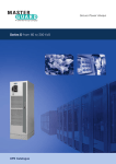
Secure Power Always
Trinergy from 200 to 1200 kVA
UPS Catalogue
Important note!
The technical data enclosed is for general information.
Please note that the operating instructions and references
indicated on the products are for installation, operation and
maintenance.
Product designations
All product designations used are trademarks or product
names of Chloride Group PLC or its subsidiary companies.
This publication is issued to provide outline information and
is not deemed to form any part of any offer or contract.
The company has a policy of continuous product
development and improvement and we therefore reserve
the right to vary any information quoted without prior notice.
Person to contact
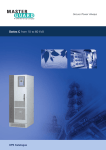
Uninterruptible Power
Supply Systems
Trinergy
from 200 to 1200 kVA
UPS Catalogue • 2009
01
Scope
2
General Requirements
2
System Description
2
AC/DC IGBT Converter (Rectifier)
7
DC/DC IGBT Converter (Booster/Battery Charger)
8
DC/AC IGBT Converter (Inverter)
9
Power Interface/Electronic Static Switch (Bypass)
11
Functioning Modes/ Trinergy Algorithm
12
Monitoring and Control, Interfaces
14
Mechanical Data
17
Environmental Conditions
17
Technical Data (400 to 1200 kVA)
18
Options
21
Appendix: Planning and Installation
23
MKA4CAT0UKTRIN/Rev 1-09/2009/UK
CHLORIDE Trinergy
UPS Systems from 200 to 1200 kVA
1 Scope
This specification describes a continuous
duty three-phase, solid state, full IGBT
(Insulated Gate Bipolar Transistor),
double conversion uninterruptible power
supply (UPS) system. The UPS will
automatically provide continuity of
electrical power, within defined limits
and without interruption, upon failure or
degradation of the commercial AC
source.
The continuity of conditioned electric
power will be delivered for the time
period defined by the battery system.
The rectifier, the inverter, and other
mission critical converters within the
UPS, are driven by vector control
algorithms (covered by patents 95
P3875, 95 P3879 and 96 P3198) running
on dedicated digital signal processor
(DSP) systems operating in combination
with the Trinergy algorithm.
2 General requirements
2.1 Applied standards
Chloride
operates
a
Quality
Management System which complies
with BS EN ISO 9001-2000 for
the design, manufacturing, sales,
installation, maintenance and service
of uninterruptible power supply
systems. The Chloride Environmental
Policy and Management Systems
comply with EN ISO 14 001. Chloride is
also committed to implementing a
policy of continuous improvement to
its production processes and pollution
reduction. Trinergy will carry the
CE mark in accordance with the
European Safety Directive 2006/95
(superseding the 73/23 and successive
amendments) and European EMC
directive
2004/108
(superseding
the 89/336, 92/31 and 93/68). Trinergy
is designed and manufactured
in accordance with the following
international standards:
• IEC/EN62040-1-1 general and safety
requirements
• EN62040-2 EMC requirements
• IEC/EN62040-3 operating requirements
• Classification according to IEC/EN
62040-3: VFI-SS-111
2.2 Safety
In terms of general and safety
requirements, the UPS conforms to
standard IEC/EN 62040-1-1 governing
use in unrestricted access locations.
2.3 EMC and surge suppression
Electromagnetic effects will be minimised
in order to ensure that computer systems
and other similar electronic loads will
neither be adversely affected by nor affect
the UPS. The UPS will be designed to
meet the requirements of EN 62040-2,
class C3. The manufacturer and customer
in partnership agree to ensure the
essential EMC protection requirements
for the specific resulting installation.
2.4 Neutral connection and grounding
Trinergy output neutral will be electrically
isolated from the UPS chassis. The input
and output neutral connections are the
same, i.e. they are solidly tied together.
Therefore the UPS will not modify the
state of the upstream neutral, in any
operating mode, and the neutral state of
the distribution downstream from the
UPS is imposed by the mains one.
Trinergy will be used in installations with
grounded neutral; for further details
please contact Chloride Technical Support.
2.5 Materials
All materials and components comprising
the UPS will be new and of current
manufacture.
3 System description
3.1 The system
The UPS will provide high quality AC
power for electronic equipment loads
and will offer the following features:
•
•
•
•
•
Trinergy technology
Maximum energy savings
Scalability up to 9.6 MW
Increased power quality
Full input Power Factor Correction
(PFC) and very low THDi
MKA4CAT0UKTRIN/Rev 1-09/2009/UK
• Full compatibility with any TN and
IT installation
• Full compatibility with any standby
power generator
• Full compatibility with all types of
loads with PF up to 1 without
derating
• Power blackout protection
• Advanced battery care
• Transformer free design
02
The UPS will automatically provide
continuity of electrical power, within
defined limits and without interruption,
upon failure or degradation of the
commercial AC source.
In a single UPS Trinergy can provide a
parallel of up to six power modules
operating in parallel for capacity or
redundancy.
CHLORIDE Trinergy
UPS Systems from 200 to 1200 kVA
3 System description
3.2 Models available
Input/output
connections
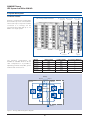
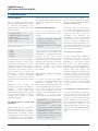
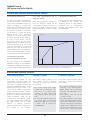
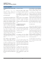
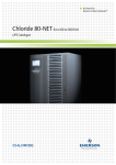
CAD - Trinergy internal architecture
Trinergy is a high power modular UPS
and is made up of one central I/O Box
with a total of up to six power modules
connected to it. Trinergy can be
customised from 200 kVA up to 1.2
MVA in one single system.
200 kVA
200 kVA
Three phases
of inverter
Three phases
of rectifier
I/O Box
Battery
connection
Booster
Static
bypass
Figure 1. Trinergy CAD model.
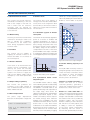
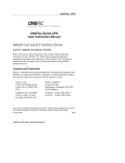
The following configurations are
available as standard while for all the
other configurations it is possible to
separately purchase the I/O Box, power
modules and connection kit.
Model
Rating (kVA)
I/O Box (kVA)
N° of Power Modules
Trinergy
400
400
2
Trinergy
600
800
3
Trinergy
800
800
4
Trinergy
1000
1200
5
Trinergy
1200
1200
6
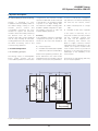
Primary
Bypass
Output
Power module
200 kVA
Power module
200 kVA
Maintenance
Battery
Figure 2. Trinergy 400 kVA single-line diagram.
03
MKA4CAT0UKTRIN/Rev 1-09/2009/UK
CHLORIDE Trinergy
UPS Systems from 200 to 1200 kVA
3 System description
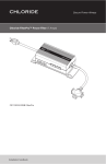
3.3 I/O Box
The central I/O Box is a common interface
for power connection and user interaction.
The central I/O Box is available in three
different ratings: 400 kVA, 800 kVA and
1200 kVA. A maximum of two, four or
six 200 kVA power modules can be
connected to the I/O Box, depending
on its rating. The modular architecture
of Trinergy allows power modules to be
added without the need for any
modification to the current installation.
The following switches are located on
the front of this box:
•
•
•
•
•
Bypass
Input
Output
Maintenance bypass
Battery
This allows any maintenance work to
be carried out without disconnecting
the load. Input and output terminals, as
well as the battery connection are
located in the central I/O Box which
allows for top or bottom cable entry.
It will be possible to implement a manual uninterrupted bypass of the complete system in order to enable maintenance work to be carried out on the
system. The bypass supply will continue to feed the load. In this case the
UPS will be voltage-free as it will be
disconnected from the supply networks. In this case, maintenance work
on the UPS can be carried out without
affecting the connected electric load.
be disconnected from the UPS by
means of an external switch (e.g.
situated in the battery cabinet). The
UPS will continue to operate and meet
the performance criteria specified with
the exception of the battery backup
time.
The central I/O Box houses a 12.1 inch
LCD touch screen which allows for
easy monitoring of the system and
individual modules. Using the touch
screen it is also possible to access the
service history log for faster, simpler
maintenance. Single point of failure is
completely eliminated as all the power
components, as well as the control
boards, are present in each power
module.
Batteries can be either centralised or
distributed with connection always being
from the I/O Box. If the battery is taken
out of service for maintenance, it must
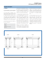
FRONT
FRONT
FRONT
400 kVA
800 kVA
1200 kVA
Figure 3. Trinergy I/O Box footprint.
MKA4CAT0UKTRIN/Rev 1-09/2009/UK
04
CHLORIDE Trinergy
UPS Systems from 200 to 1200 kVA
3 System description
3.4 Power Modules
Each of the Trinergy power modules
has eight separate drawers which allow
for improved serviceability of the
individual power modules. The power
module contains:
•
•
•
•
•
Full IGBT rectifier,
IGBT Booster/battery charger
IGBT inverter
Power interface/Static Bypass
Power control
Each power module will be fitted with
the following switches:
•
•
•
•
Input
Output
Battery
Neutral
These switches will make it possible to
completely isolate a single power
module for maintenance or service
operation. As a result, there will be no
interruption to the power of the critical
load when it is necessary to take a
power module out of service for
maintenance or repair. Isolation will
be complete and all serviceable
components such as fuses, internal
power functional modules etc will be
isolated.
Remaining power modules will
continue to power the load making it
possible to perform maintenance
operation on the system while
maintaining the highest level of power
protection and avoiding the need to
switch the whole system to manual
maintenance bypass.
3.5 Microprocessor control and
diagnostics
Operation and control of the UPS will
be provided through the use of microprocessor-controlled logic. Indications,
measurements and alarms, together
with battery autonomy, will be shown
on a graphic LCD touch screen display.
The procedures for start up, shutdown
and manual transfer of the load to and
from bypass will be explained in clear
step-by-step sequences on the LCD
display.
Several algorithms included in the
vector control firmware are covered by
patents owned by Chloride (95 P3875,
95 P3879 and 96 P3198).
3.6 Control and diagnostics
The precise control of Trinergy allows
it to quickly and seamlessly activate
one of the three different functioning
modes of the UPS in order to
accomplish
the
efficiency
and
effectiveness of each of the standard
configurations. At the same time,
Trinergy continues to maintain the
performance and power protection of a
Class 1 (IEC 62040-3) UPS for the load
and perfect input power conditioning
for the upstream distribution.
Control of the electronic power
modules will be optimised in order to
provide:
• Optimum three-phase supply and
conditioning of the load
• Controlled battery charging
• Minimum effects upon the supply
network
Trinergy houses an advanced digital
control platform that combines the
advantages of a double DSP which
executes all the vector control
algorithms and the Microcontroller
which gives maximum communication
flexibility whilst interfacing all internal
and external signals. Thanks to this
platform
Trinergy
will
achieve
the most powerful control in the
UPS industry.
3.6.1 Vector control & Trinergy
algorithm
To ensure the quick and flexible
processing of measuring data, special
arithmetic
algorithms
will
be
implemented in DSP, rapidly generating
controlled variables as a result. This will
thus render possible the real-time
control of the inverter electronics,
resulting in obvious advantages in the
performance
of
the
power
components. These advantages will be:
• Improvement of short circuit
behaviour, as individual phases can
be controlled faster
• Synchronism or phase angle
precision between UPS output and
bypass supply even in the case of a
distorted mains voltage
• High flexibility in parallel operation:
parallel Trinergy systems may be
housed in separate rooms.
05
3.6.2 Preventive monitoring
In order to maximise the reliability of
the system, the control unit will
monitor a wide number of operating
parameters for the rectifier, inverter
and battery. All vital operating
parameters, such as temperatures,
frequency and voltage stability at the
system input and output, load
parameters and internal system values
will be constantly monitored and
controlled for irregularities. The system
will react automatically before a critical
situation arises either for the UPS or
the load, in order to ensure the supply
of the load even in these difficult
conditions.
3.6.3 Telediagnosis and telemonitoring
In all the above modes of operation,
the UPS may be monitored and
controlled from a remote location such
as a service centre, in order to maintain
system reliability at nominal levels.
Even during complete shutdown of the
UPS, information relating to the
operating parameters will not be lost
thanks to non volatile FRAM which will
store the information for up to 45
years.
MKA4CAT0UKTRIN/Rev 1-09/2009/UK
CHLORIDE Trinergy
UPS Systems from 200 to 1200 kVA
3 System description
3.6.4 Serviceability and commissioning
Trinergy is designed for easy
installation and serviceability thanks to
the drawer design, making it a full
modular
service
solution
and
considerably minimising the time
needed for repairs. All functional
modules can be removed by extracting
the drawers from the front of
machine. Each UPS will be equipped
with ID card, including all main UPS
working parameters. This card, reduces
the MDT shortening service and
commissioning operations.
configurations. The maximum number
of power modules that can be connected
to the I/O Box is six, providing 1.2 MW
of power in one single Trinergy UPS.
The maximum number of Trinergy UPS
possible in parallel configuration is eight.
The parallel connection of UPS will
increase reliability and power.
Reliability
If the installation requires a redundant
configuration the power of each UPS
should not be lower than Ptot/(N-1)
where:
Ptot = Total load power
N = Number of Power Modules in parallel
1 = Minimum coefficient of redundancy
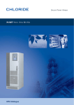
3.7 Parallel Configuration
3.7.1 Paralleling principle
The Trinergy series of uninterruptible
power supply systems will be
connectable in parallel for multi-module
Under normal operating conditions, the
power delivered to the load will be
shared between the number of power
modules connected to the parallel bus.
UPS 1
BATT
UPS 2
Pov = Max overload power of a single
UPS
N = Number of UPS units in parallel
In the event of failure by one of
the power modules, the faulty module
will be completely isolated and
the load will be supplied from
the remaining units without any
break in supply continuity. Internal
redundancy allows maintenance to be
carried out on specific modules while
other modules continue to provide full
protection to the load with enormous
advantages on the availability of the
whole system.
A maximum of eight Trinergy UPS may
be connected in parallel.
UPS n
BATT
SBS
Figure 4. Trinergy parallel systems.
MKA4CAT0UKTRIN/Rev 1-09/2009/UK
In case of overload the configuration
may deliver Pov x N without transferring
the load onto the reserve, where:
06
Load
CHLORIDE Trinergy
UPS Systems from 200 to 1200 kVA
3 System description
3.7.2 Modular Parallel
The Trinergy UPS will be capable
of operating in a modular parallel
configuration.
The parallel option will simply consist
of screened data cables connected to
the neighboring UPS systems (closed
loop ring bus).
A multi-module system will be
controlled and monitored automatically
by controlling the individual UPS
modules. The parallel system control is
distributed among the units (no
master/slave architecture). The bypass
lines and inverters included in each
UPS share the load. The load sharing
among the UPS parallel system ("load
on inverter" mode) will be achieved
with a tolerance of less than 3% at
nominal load.
The loop ring bus will allow the parallel
to share the system load even with an
interruption in the data cable (first
failure proof system).
3.7.3 Circular Redundancy
Circular redundancy is able to optimise
the efficiency of the UPS even at low
partial loads. In the case that the
total number of power module is
not necessary to power the output
load, Trinergy will evaluate the real
number of power modules required
(maintaining also the level of
redundancy requested) to power the
actual load. As soon as an increase of
the load is verified the power modules
will be started up.
The main objective of “circular
redundancy” is to power on only the
minimum number of inverters required
at that level of load, ensuring a periodic
turnover of all the available modules
(cores). This ensures that the highest
level of efficiency is maintained at all
times.
4 AC/DC IGBT Converter (Rectifier)
4.1 Primary input
The three-phase current taken from the
commercial AC source will be converted
to a regulated DC voltage by an IGBT
rectifier. In order to protect the power
components within the system each
phase of the rectifier input will be
individually fitted with a fast-acting fuse.
As shown in Figure 1, the IGBT rectifier
will provide DC power to the DC/AC
output converter (IGBT inverter) and
to the DC/DC battery converter
(booster/battery charger) when the latter
is working in battery charger mode.
4.2 Total Input Harmonic Distortion
(THD) and Power Factor (PF)
The maximum voltage THD (THDV)
permitted on the rectifier input (either
from the utility or generator) will be 15%
(normal operation is guaranteed up to
8%). The maximum current THD injected
into the mains (THDI) will be less than
3% at maximum input power and
input voltage THDV < 1% (nominal input
voltage and current). Under these
conditions the input power factor (PF) will
be > 0.99. Under other input conditions
and with other output load fractions the
THDI will be < 5%. This means that the
Trinergy, in double conversion mode, will
be seen by the primary mains sources
and distribution as a resistive load (i.e. it
will absorb only active power and the
current waveform will be practically
sinusoidal),
thus
ensuring
total
compatibility with any power source.
4.3 Operation with diesel generator
In order to obtain the required THD on
input voltage, the coordination
between a diesel generator and UPS
will be based on the generator’s subtransient reactance, as opposed to its
short-circuit reactance.
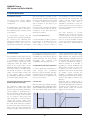
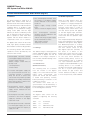
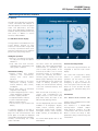
4.4 Soft start
With the UPS logic properly powered,
after applying the input voltage the rectifier
starts an additional programmable current
soft start (1-90 seconds). This procedure
AC
Input
Current
results in a gradual and soft walk-in of the
current taken from the input voltage
supply network. This ensures that any
standby generator is gradually introduced
into the UPS input, as shown in Figure 5.
To avoid the simultaneous start-up of
different rectifiers, it is possible to
programme a hold-off dedicated start
delay (1-180 seconds) for each unit.
In addition, the UPS includes an ‘on
generator’ function which, when activated
via floating contact, provides the
possibility of inhibiting either battery
charging, synchronisation of the inverter to
the direct line supply or transfer to the
direct line.
When the UPS is operating with a
Flywheel system, the corresponding holdoff and soft start parameters must be set
according to the requirements of the
genset. Please contact the technical
support for more information.
Hold-off
Delay
(1- 180s)
Mains Failure
Current
soft
start
(1-90 s)
Mains OK
Time
Figure 5. Rectifier soft start.
07
MKA4CAT0UKTRIN/Rev 1-09/2009/UK
CHLORIDE Trinergy
UPS Systems from 200 to 1200 kVA
5 DC/DC IGBT Converter (Booster/Battery Charger)
5.1 Booster/Battery Charger
As seen in Figure 1, this bidirectional
IGBT DC/DC converter will have the
following functions:
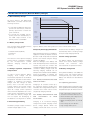
(Nominal Voltage)
Input AC
Voltage
100%
85%
80%
• To recharge the batteries taking the
power from the DC bus, when the
primary input mains is within the
given tolerances
• To provide the suitable full DC
power, taken from the batteries, to
the IGBT output inverter if the
primary mains is unavailable.
Time
Battery
status
Charging/
floating
idle
(no discharge)
5.2 Battery charger mode
This converter will be operable with the
following types of batteries:
T1
The selection of the optimum charging
method will be completely managed
by the microprocessor. Several
different charging methods are
available.
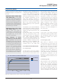
5.3 Voltage regulation, temperature
compensation
In order to ensure optimum battery
charging, float voltage will be
automatically adjusted to the ambient
temperature. The IGBT rectifier will be
capable of supplying the battery
charger with DC voltage at rated
power, even if the UPS input AC
voltage is below the nominal voltage
specified. A further reduction of the
input AC voltage (within specified
limits which are dependent also on the
output power requested by the load)
will inhibit the battery charger but
will not require the discharging of
the batteries. See Figure 6 for details.
5.4 Residual ripple filtering
The battery charger output will have a
residual voltage ripple of <1%.
MKA4CAT0UKTRIN/Rev 1-09/2009/UK
Time
Figure 6. Battery status during reduction of the commercial AC source.
5.5 Capacity and charging characteristics
• Sealed Lead Acid (VRLA)
• Lead Acid
• Ni - Cd
T2
When the primary mains is not suitable to
supply the rectifier, the DC/DC converter
(booster mode) will provide the required
power to the inverter using the energy
stored in the battery.
After the discharge of the battery and
when the input AC power is restored, the
rectifier will power the inverter and
recharge the batteries through the DC/DC
converter in battery charger mode. The
following charging methods are an
example of the several methods available,
giving the possibility of matching the
following different types of accumulators:
5.5.1 Sealed, maintenance-free lead
acid accumulators:
threshold value the battery charger will
automatically return to floating voltage
level (two-step charging method).
5.6 Over voltage protection
The battery charger will automatically
switch off if the DC battery voltage
exceeds
the
maximum
value
associated with its operational status.
5.7 Battery management
Using advanced battery care (ABC) the
Trinergy series will maximise battery
running time by up to 50%. The main
battery care features are described as
follows.
5.7.1 Operating parameters
Charging is at constant current up to
the maximum floating voltage level.
Thereafter the voltage will be kept at a
constant level within narrow limits
(single-step charging method).
5.5.2 Sealed, low-maintenance lead
acid
accumulators
or
NiCd
accumulators:
Charging is at increased charging
voltage and constant charging current
(boost charge phase). When the
charging current falls short of a lower
08
When operating with a maintenance free,
valve regulated lead acid battery (VRLA),
the parameters per cell will be as follows:
•
•
•
•
•
End of discharge voltage (V) 1.65
Shutdown imminent alarm (V) 1.75
Minimum battery test voltage (V) 1.9
Nominal voltage (V) 2.0
Battery discharging alarm (V) 2.20 @
20°C
• Float voltage (V) 2.27 @ 20°C
• High voltage alarm (V) 2.4
CHLORIDE Trinergy
UPS Systems from 200 to 1200 kVA
5 DC/DC IGBT Converter (Booster/Battery Charger)
5.7.2 Automatic battery test
The operating condition of the batteries
will be automatically tested by the
control unit at selectable intervals, e.g.
weekly, fortnightly or monthly. The
battery test can be performed in each
of the different functioning modes.
A short-time discharge of the battery
will be made to confirm that all the
battery blocks and connecting
elements are in good working order.
In order to preclude a faulty diagnosis,
the test, at the earliest, will be
launched 24 hours after the latest
battery discharge. The battery test will
be performed without any risk to the
load, even if the battery is completely
defective. Users will be alerted to a
detected battery fault. The battery test
will not cause any degradation in terms
of the battery system life expectancy.
5.7.4 Time compensated end of
discharge voltage
When the discharge time exceeds one
hour, the shutdown voltage will be
automatically increased, as shown in
Figure 6 for VRLA, to avoid prolonged
battery discharge as a result of a light
load.
Trinergy uses sophisticated algorithms
to determine the battery life
remaining, based on real operating
conditions such as temperature,
discharge and charging cycles, and
discharge depth.
Voltage per cell
1.80
1.75
1.70
5.7.3 Ambient temperature
compensated battery charger
The float voltage will be automatically
adjusted as a function of the temperature
in the battery compartment (-0.11% per °C)
in order to maximise battery operating life.
5.7.5 Remaining battery life
1.65
0
1
2
3
4
5
6
7
8
9
10
Time (hours)
Figure 7. End-of-discharge voltage in relation to discharge time.
6 DC/AC IGBT Converter (Inverter)
6.1 AC voltage generation
6.2 Voltage regulation
6.3 Frequency regulation
From the DC voltage of the
intermediate circuit the inverter will
generate sinusoidal AC voltage for the
user load on the basis of pulse-width
modulation (PWM). By means of the
digital signal processor (DSP) of the
control unit, the IGBT of the inverter
will be controlled so that DC voltage is
divided up into pulsed voltage packets.
Thanks to a low-pass filter, the pulsewidth modulated signal will be
converted into sinusoidal AC voltage.
No isolation transformer is needed for
the IGBT inverter, with the great
benefits of: energy conversion
efficiency and reduction in physical size
and weight of the modules.
The inverter output voltage on the
three phases will be individually
controlled to achieve the following
performances:
The inverter output frequency will be
controlled to achieve the following
performances:
• The inverter steady state output
voltage will not deviate by more
than ±1% in a steady state
condition for input voltage and
load variations within the quoted
limits
• The inverter transient voltage will
not exceed Class 1 limits when
subjected to application or removal
of 100% load as defined by
IEC/EN62040-3
09
• The inverter steady-state output
frequency, when synchronised to
bypass supply, will not deviate by
more than ±1% adjustable to ±2%,
±3%, ±4%
• The frequency slew rate will be
<1 Hz per second
• The output frequency of the inverter
will be controlled by a quartz oscillator
which can be operated as a free running unit or as a slave for synchronised
operation with a separate AC source.
The accuracy of the frequency control
will be ±0.1% when free-running
MKA4CAT0UKTRIN/Rev 1-09/2009/UK
CHLORIDE Trinergy
UPS Systems from 200 to 1200 kVA
6 DC/AC IGBT Converter (Inverter)
6.4 Total Harmonic Distortion
6.10 Short circuit
The inverter will provide harmonic
neutralisation and filtering to limit the
THD on the voltage to less than 1%
with a linear load. For reference
non-linear load (as defined by
IEC/EN62040-3) the THD will be limited
to less than 3%.
The inverter short circuit capacity of
Trinergy for the first 10ms will be 300%
for any short circuit configuration. After
the first 10ms, it will limit the current to
150% for no longer than 5s and then it
will shut down.
6.5 Neutral sizing
6.11 Automatic upgrade of inverter
rated power
with PF up to 1 will be supplied by the UPS
without any derating since the inverter will
be able to work at 100% of its power.
KVAr
Leading
%
100
100%
KVA
Cos ϕ 0.5
80
Cos ϕ 0.8
60
Cos ϕ 0.9
The inverter will be capable of
supplying an overload of 125% for 10
minutes and 150% for one minute of
the nominal power.
Output Power
KVA
6.6 Overload
20
0
Cos ϕ 1
25
20
40
75
100 % kW
Cos ϕ 0.9
60
Cos ϕ 0.8
80
100
50
100%
KVA
The inverter will automatically upgrade its
power as a function of ambient and
operating temperatures, as shown in
Figure 8. In the most common conditions
(25°C) Trinergy will provide 10% more
power than nominal. In these conditions
the battery charge will be reduced in
correspondence. The limit of the active
power available at the output of the UPS
is nevertheless obtained considering the
nominal apparent power with output PF 1.
100%
The sizing of the inverter neutral will be
oversized on all ratings in order to be
able to manage the combination
of harmonics on the neutral wire
when driving single-phase reference
non-linear loads.
40
Cos ϕ 0.6
KVA
100%
Lagging
%
Figure 9. Power Factor Output Diagram.
6.7 Inverter shutdown
6.13 Active Filtering Capacity in VI
mode
110
In the event of an internal failure the
inverter will be immediately shut
down by the control unit. The UPS
device or the parallel-operated UPS
systems will continue to supply the
load from the bypass supply without
interruption, if it is within permissible
limits.
Ambient
Temperature
105
100
15
25
30
40
°C
Figure 8. Automatic power upgrade.
6.12 Symmetrical Power Factor
Output Diagram
6.8 Output voltage symmetry
The inverter will guarantee the
symmetry of the output voltages at
±1% for balanced loads and ±3% for
100% unbalanced loads.
6.9 Phase displacement
The phase angle displacement
between the three-phase voltages will
be:
• 120° ± 1° for balanced loads
• 120° ± 3° for unbalanced loads
(0, 0, 100%)
MKA4CAT0UKTRIN/Rev 1-09/2009/UK
The full IGBT inverter is able to supply,
without derating, all kinds of loads (leading
and lagging) with a Power Factor up to 1.
This behavior is achieved thanks to the
perfect dimensioning of all components of
the output stage, which allows the
obtaining of a Power Factor output diagram
perfectly symmetrical respect to zero.
Thanks to this feature, which is unique in
the market, Trinergy offers maximum
flexibility and compatibility with each
installation and means that the customer
doesn’t have to worry about future
modifications of the loads with a different
Power Factor. As shown in Figure 9, it is
clearly evident from the two blue areas
that every kind of load (leading or lagging)
10
The DC/AC IGBT inverter by means of
the digital signal processor (DSP) of the
control unit will be controlled so that it
can operate as series and parallel
active filter if this allows a higher
efficiency level to be achieved.
Inverter as a parallel active filter: the
inverter will work as a current
controlled generator, generating a
current that compensates the reactive
and harmonic content of the load.
Inverter as a series active filter: the
current of the active filter will have a shape
intended to compensate the bypass line
voltage in order to be able to remain inside
the tolerance limits. This is possible by
operating together with the Power
Interface containing a series inductance
that will serve one main purpose; that
of adding a small line impedance
for the active voltage compensation
by interacting with the current of
the active filter generated by the inverter.
CHLORIDE Trinergy
UPS Systems from 200 to 1200 kVA
7 Power Interface/Electronic Static Switch (Bypass)
7.1 General
The Power Interface is made up of a
bypass static transfer switch with an
upstream choke. This interface will power
the load whenever the load and network
conditions allow it to be able to take
advantage of the Maximum Energy
Saving mode (VFD) and the High
Efficiency & Power Conditioning mode
(VI). In interactive mode the inverter is
able to operate as series active filter
together with the Power Interface to
compensate small out of tolerance.
The bypass static switch will be a fully
rated, high speed, solid-state transfer
device rated for continuous duty operation.
7.2 Backfeed protection
• The uninterrupted transfer from
the inverter to the bypass supply
will be inhibited in the following
situations:
-bypass supply voltage outside
limits
-failure of electronic bypass switch
• The
uninterrupted
automatic
retransfer may be inhibited in the
following situations:
-manual switching to bypass supply
via the maintenance switch
-UPS output overload
-frequency converter.
7.1.1 Voltage
The following transfer and retransfer
operations will be provided by the
electronic static switch:
• Uninterrupted automatic transfer
to the bypass supply in the event of:
-inverter output overload
-battery voltage outside limits in
backup mode
-over-temperature
-inverter failure
• If inverter and bypass supply are
not synchronised at the time of a
necessary transfer, a switching
delay can be set to protect the
critical load. This prevents possible
damage to the load by unintentional
phase shift (a delay of 20ms is the
preset standard value).
• Uninterrupted manual transfer/
retransfer to and from the bypass
supply will be initiated from the
control panel.
• Uninterrupted automatic transfer/
retransfer to and from the bypass
supply by activation of the digital
interactive mode.
• Uninterrupted automatic retransfer
from the bypass supply, as soon as
the inverter regains the capacity to
supply the load.
The default voltage of the bypass line
will be 230/400 V RMS. Any transfer
from inverter to bypass line will be
inhibited if the voltage is beyond a
limit of ±10% (standard setting) of the
nominal voltage.
7.1.2 Transfer time
(double conversion)
The switching time for a transfer
from the inverter to the bypass
supply or vice versa will be less than
0.5ms when synchronised. The
system will ensure that the inverter
is stable and operating normally
before permitting a retransfer of the
load back to inverter.
The transfer time when out of
synchronisation will be defined by a
preset parameter to prevent damage
to the load by phase reversal.
When the UPS bypass input line
is powered off, there is normally
no dangerous voltage/current/power
present on the UPS bypass input.
However, when there is a fault in
the bypass static switch there is the
risk that electric power will appear
on the UPS bypass input terminals.
In this case the inverter powers the
critical load and the upstream input
power line.
This unexpected potentially dangerous
power can propagate in the upstream
distribution through the faulty bypass
line. Backfeed protection is a safety
device which prevents any potential
risk from electric shock on the
UPS bypass input AC terminals, in
the event of a failure of the
bypass static switch SCR. The control
circuit will include a contact (available
for the user) which activates an
external isolating device, such as an
electromechanical relay or a tripping
coil, upon backfeed detection. In
compliance with IEC/EN 62040-1-1, the
isolating device is not included in
the UPS. The external isolating device
will be a 4 pole (three phases
plus neutral) air gap isolator and
will be defined according to clause
5.1.4 of the previously cited standard.
7.1.3 Overload
The bypass static switch will be
capable of supporting the following
overloads:
125%
150%
700%
1000%
for
for
for
for
10 minutes
1 minute
600 milliseconds
100 milliseconds
11
MKA4CAT0UKTRIN/Rev 1-09/2009/UK
CHLORIDE Trinergy
UPS Systems from 200 to 1200 kVA
8 Functioning Modes
Trinergy incorporates the three existing
standard topologies in one transformerfree UPS:
• Maximum Power Control mode
(IEC 62040-3 VFI): is the double
conversion mode which provides the
highest level of power conditioning. It
protects the load from all types of
electrical network disturbances using
a greater amount of energy. Efficiency
at full load with the latest transformer
free technology is over 95%.
• Maximum Energy Saving mode
(IEC 62040-3 VFD): this mode
detects when the need for
conditioning is non-existent and
allows energy flow to pass through
the bypass line. In this case
efficiency reaches 99%.
• High
Efficiency
&
Power
Conditioning mode (IEC 62040-3
VI): compensates only the main
disturbances such as the load THDi,
the load PF and main sags and swells.
The energy used is derived from the
use of the inverter as an active filter
giving all the necessary reactive
power. In a typical condition this
mode will have an efficiency of
between 96 and 98%, depending on
the load type (e.g. non linear, linear
etc.) and the input mains conditions.
The precise control of Trinergy allows it
to quickly and seamlessly activate one
of the three different functioning
modes in order to accomplish the
efficiency and effectiveness of each of
the standard configurations. At the
same time, Trinergy continues to
maintain the performance and power
protection of a Class 1 (IEC 62040-3)
UPS for the load and perfect input
power conditioning for the upstream
distribution.
The activation of one of the three different
functioning modes is based on real time
power tracking of the main parameters
related to the input network and to the
output load.
(For any further detail on how the UPS
select the functioning mode to be
activated please refer to the application
note “UPS Functioning Modes”)
If the observed variables listed below are
outside the ranges described the UPS will
activate a different functioning mode.
Parameters can be modified by the
service engineer upon request. These
conditions refer to full output load.
8.1 Double Conversion Mode (VFI)
8.1.1 Normal (VFI)
The UPS inverter continuously supplies
the critical AC load. The rectifier derives
power from the commercial AC source
95 - 99% efficiency at down to 20% load
and converts it into DC power for the
inverter and the battery charger. The
battery charger keeps the battery
in a fully charged and optimum
operational condition. The inverter
converts the DC power into clean and
regulated AC power which is supplied
to the critical load (conditioned line)
and is synchronised with the bypass
supply frequency. This ensures
that any automatic transfer to the
bypass supply (due to an overload
etc.) is frequency synchronised
and does not cause interruption to
the critical load.
8.1.2 Overload (VFI)
In the event of an inverter overload,
manual stop or failure, the static switch
will automatically transfer the critical
load to the bypass line without
interruption.
8.1.3 Emergency (VFI)
Upon failure or reduction of the
commercial AC source (see section 12)
the inverter will supply the critical load,
drawing power from the associated
battery through the battery booster.
There will be no interruption to the
critical load upon failure, reduction or
restoration of the commercial AC
source. While the UPS is powered by
the batteries, indications will be
provided of actual autonomy time
remaining as well as the duration of the
mains failure.
100
Max Efficiency
98
%
96
8.1.4 Recharge (VFI)
Min Efficiency
94
Upon restoration of the commercial AC
source, even in the case that the
batteries are completely discharged,
the rectifier will restart automatically
(walk in) and gradually take over both
the inverter and battery charger. This
function will be fully automatic and will
cause no interruption to the critical load.
92
% 90
88
86
84
82
80
0%
20%
40%
60%
80%
100%
Load
Figure 10. Trinergy efficiency values using circular redundancy.
MKA4CAT0UKTRIN/Rev 1-09/2009/UK
12
CHLORIDE Trinergy
UPS Systems from 200 to 1200 kVA
8 Functioning Modes
8.2 Maximum Energy Saving mode
(VFD)
This
operational
mode
allows
significant
energy
savings
by
increasing the overall AC/AC efficiency
of the UPS up to 99%.
8.2.1 Normal (VFD)
The operating mode will depend on the
quality of the mains supply in the shortterm past and on the electrical
characteristic of the load. If the line quality
remains within permitted tolerance
parameters in this timeframe, the direct
line will provide continuous supply to
the critical AC load through the power
interface. The IGBT inverter control will
remain in constant synchronisation
with the direct line without driving
the IGBT. This ensures that the load
can be transferred to the conditioned
line without any break in supply
where there is a deviation from the
selected input power tolerance levels.
If the direct line failure rate has been
outside permitted parameters in this
timeframe, Trinergy will supply the
load from the conditioned line. The battery
charger supplies the energy necessary for
maintaining maximum charge to the
battery.
8.2.2 Transfer to VFI Emergency
(due to mains supply failure or
variance beyond tolerance limits)
If Trinergy is supplying the load via
the direct line and the bypass mains
supply varies beyond tolerance levels
(adjustable using the software), the load
will be transferred from the direct line to
the conditioned line. The load is powered
from the mains via the rectifier and
inverter, (provided the input mains
remains within the tolerances stated in
chapter 12). Should the input mains fall
below the lowest limit, the batteries will
be used to power the load via the
inverter.
8.2.3 Return to VFD
When the mains supply returns
to within tolerance limits, Trinergy
will continue to supply the load via
the conditioned line for a period of
time dependant on the direct line
failure rate (the conditioned line draws
power from the mains not the
battery).
When the direct line has stabilised,
Trinergy returns to normal operation.
The battery charger automatically
begins to recharge the battery
so that maximum autonomy is
guaranteed in the shortest possible
time.
8.3 High Efficiency & Power
Conditioning mode (VI)
This
functioning
mode
allows
significant energy savings by operating
with a typical efficiency between 96%
and 98% while providing power
conditioning to the load.
8.3.1 Normal (VI)
The operating mode will depend
on the quality of the mains supply
in the short-term past and on
the electrical characteristic of the
load.
If, the line quality remains within
permitted tolerance parameters and
the load needs power conditioning,
(THDi, THDv, PF) the power interface
will provide continuous supply to the
critical AC load while the inverter
operates as series and parallel active
filter.
The IGBT inverter will be able to
compensate the power factor of
the load, the current harmonic
distortion and the voltage harmonic
distortion guaranteeing optimum
power conditioning to the load
while maintaining the highest level
of efficiency.
13
8.3.2 Transfer to VFI Emergency
(due to mains supply failure or
variance beyond tolerance limits)
If the bypass mains supply varies
beyond tolerance levels (adjustable
using the software) that cannot be
compensated through the active filter,
the load will be transferred from the
direct line to the conditioned line. The
load is powered from the mains via the
rectifier and inverter, (provided the
input mains remains within the
tolerances stated in section 12). Should
the input mains fall below the lowest
limit, the batteries will be used to
power the load via the inverter.
8.3.3 Return to VI
When the mains supply returns within
tolerance limits, Trinergy will continue
to supply the load via the conditioned
line for a period of time dependant on
the direct line failure rate (the
conditioned line draws power from the
mains not the battery). When the
direct line has stabilised, Trinergy
returns to normal VI operation. The
battery charger automatically begins to
recharge the battery so that maximum
autonomy is guaranteed in the
shortest possible time.
For further details on the activation of
the three different functioning modes
refer to Chloride functioning modes
application note.
MKA4CAT0UKTRIN/Rev 1-09/2009/UK
CHLORIDE Trinergy
UPS Systems from 200 to 1200 kVA
9 Monitoring and Control, Interfaces
9.1 General
The UPS will incorporate the necessary
controls, instruments and indicators to
allow the operator to monitor the system
status and performance, and take
action where appropriate. Furthermore,
interfaces allowing extended monitoring
and control, in addition to service
functions, will be available.
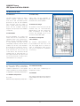
9.2 LCD Touch Screen display
Trinergy features a standard LCD touch
screen display, allowing for easy
interaction with the UPS. A high level
of security is provided for both, users
and service engineers via two separate
password access privilege levels.
Intelligent operation
• Monitors user-defined thresholds
for load power margin and phase
imbalance
• Logs data and event histories
regarding power, load, battery, and
other system conditions
Information tracking
• Overall system and module
readiness, with informational,
warning
and
critical
status
indicators
• Module level alerts for all major
subsystems including rectifier,
inverter, batteries, static switch,
and bypass
• Power path status via animated
single-line mimic display
• System voltages and power — input,
output and bypass, all phases
• Load vs. capacity indicator
• Load phase balance indicator
• System temperature gauge
• Battery charge indicator
• Service history logs—module and
battery
A single-line diagram of the UPS is
continuously displayed on the default
page. The main functional blocks and
power paths of the UPS are displayed
using simple universal technical symbols,
instantly communicating the overall
status of the UPS.
MKA4CAT0UKTRIN/Rev 1-09/2009/UK
Figure 11. LCD Touch Screen display.
The same screen also permanently
displays the output load percentage
measurement in dashboard style
(one for each output phase). In the
event that the UPS is not in normal
functioning mode, it is possible to
access the “Warning and Alarm”
summary page directly from the
default page. Warnings and alarms
will be identified by text strings and
codes. In battery operation, the
display will switch between warning
code and estimated backup time
in minutes.
After 30 seconds of inactivity (i.e. no
contact with screen/buttons) the
display reverts to the screen saver
page which shows the status of the
UPS (Normal, Warning, Alarm).
The text displayed by the LCD will be
available in 15 languages: English,
Italian, French, German, Spanish,
Portuguese, Turkish, Polish, Swedish,
Norwegian, Finnish, Czech, Russian,
Arabic, Chinese, all selectable by the
user.
For further details please refer to the
User Manual.
14
9.3 Start and Stop inverter
The Start and Stop push buttons are
integrated in the LCD touch screen
display.
The control will incorporate a safety
feature to prevent inadvertent
operation yet still allow for rapid
shutdown in the event of an
emergency. To stop the inverter the
user must press and hold the Stop
button for a few seconds. An audio
alarm will be activated during this
delay time.
9.4 Interface
9.4.1 Ethernet RJ45 Interface (X9)
Trinergy will be equipped with a RJ45
Ethernet interface.
This interface is a 10/100 MBit
autonegotiation
full/half
duplex
RJ45 Ethernet interface for LAN
communication with service software
PPVis. It allows the setup of UPS
parameters during commissioning and
maintenance.
CHLORIDE Trinergy
UPS Systems from 200 to 1200 kVA
9 Monitoring and Control, Interfaces
9.4.2 RS232 Service port (X3)
Trinergy will be equipped with one D type
female connector (9 pin) for serial
RS232 communication for service
purposes only.
9.4.3 LIFE.net (X6)
The service Interface is a SUB-D 9 pin
male connector for RS232 serial
communication.
Trinergy includes an XS6 connection
for the LIFE.net slot modem. If this
slot modem is not installed, this port
may be used for an external LIFE.net
kit (e.g. LIFE over IP, GSM).
the available slot expansion cards.
9.5 2*16 Pole screw connector for
input and output contacts (TB1)
9.4.4 Slot card bay (XS3 & XS6)
Trinergy will be equipped with two slot
bays available for communication card
options. One of the slots (XS6) will
be available for the LIFE.net slot
modem. The other slot (XS3) will be
available for connectivity options,
such as ManageUPS NET III adapter.
Please refer to Chloride Connectivity
Solutions for further details about
This 2*16-pole screw connector allows the
connection of: six individual configurable
output and four individual configurable
input contacts which can be programmed
via PPVis (service software tool) for a wide
range of functions. This interface is SELVisolated from the UPS primary circuits. The
maximum rating of the output contacts
must not exceed 24V and 1A (refer to
the User Manual for further details).
Output Contacts (lower row of the connector):
PIN
Status
Preset Value
PIN 1 (left)
Normally closed
Summary Alarm
PIN 2
Normally open
PIN 3
Normally closed
PIN 4
Normally open
PIN 5
Normally closed
Low Battery
PIN 6
Normally open
Normally open
PIN 7
Normally closed
AC Fail
PIN 8
Normally open
PIN 9
Common to PIN1-PIN8
N/A
PIN 10
N/A
N/A
PIN 11
Normally closed
Selectable
PIN 12
Normally open
PIN 13
Common to PIN11-PIN12
N/A
PIN 14
Normally closed
Selectable
PIN 15
Normally open
PIN 16
Common to PIN14-PIN15
Bypass Active
N/A
The Interface is SELV - isolated from UPS primary circuits.
15
MKA4CAT0UKTRIN/Rev 1-09/2009/UK
CHLORIDE Trinergy
UPS Systems from 200 to 1200 kVA
9 Monitoring and Control, Interfaces
Input Contacts (upper row of the connector):
PIN
PIN 1 (left)
Preset Value
Status
Input 1 (24VDC OUT)
Selectable
PIN 2
Input 1 (24VDC signal)
PIN 3
Input 2 (24VDC OUT)
PIN 4
Input 2 (24VDC signal)
PIN 5
Input 3 (24VDC OUT)
PIN 6
Input 3 (24VDC signal)
PIN 7
Input 4 (24VDC OUT)
PIN 8
Input 4 (24VDC signal)
PIN 9 - 16
N/A
Selectable
Selectable
Selectable
N/A
The Interface is SELV - isolated from UPS primary circuits.
9.6 LIFE.net
In order to increase the overall
reliability of Trinergy system, the
LIFE.net communication kit, providing
connection to Chloride’s LIFE.net
diagnostic service will be available.
LIFE.net will allow the remote
diagnosis of the UPS through the
IP connection (Internet connection),
telephone lines or GSM link in
order to ensure maximum reliability of
the UPS throughout its operational
life. The monitoring will be a real
24-hour, 365 day service thanks
to a unique feature that allows
trained Service Engineers to remain
in constant electronic contact with
the service centre, and therefore
the UPS. The UPS will automatically
dial-up the service centre at
defined intervals to provide detailed
information that will be analysed
in order to predict potential shortterm future problems. In addition, it
will be possible to control the UPS
remotely.
MKA4CAT0UKTRIN/Rev 1-09/2009/UK
The communication of UPS data to the
Chloride LIFE Command Centre will be
transmitted via the integrated modem
at the following intervals:
• ROUTINE: settable at intervals of
between five minutes and two
days (typically once a day)
• EMERGENCY: when a problem
occurs or parameters are beyond
tolerance limits
The service centre will analyse
historical data and issue a regular
detailed report to the customer
informing them of the UPS operational
condition and any critical states.
The LIFE.net centre allows the
possibility of activating the LIFE-SMS
delivery system option, where the
customer may receive SMS notification
which will be activated in the event of
one of the following:
• Mains power failure
• MANUAL: following a request from
the command centre
• Mains power recovery
• Bypass line failure
During the call the command centre will:
• Load supplied by reserve.
• Identify the UPS connected
• Request the data stored in the UPS
memory since the last connection
• Request real-time information from
the UPS (selectable)
16
CHLORIDE Trinergy
UPS Systems from 200 to 1200 kVA
10 Mechanical Data
10.1 Enclosure
10.3 Cable entry
The UPS will be housed in a spacesaving modular enclosure with
front doors and removable panels
(protection as per IP 20 standard).
The enclosure will be made of
zintec coated sheet steel and the
doors will be lockable. Different
degrees of IP protection are available
on request.
Cable entry will be available as
standard from the BOTTOM or from
the TOP of the central I/O Box.
10.2 Ventilation
Forced redundant air cooling will
ensure that all the components are
operated within their specification.
Airflow will be controlled according
to load demand. The UPS will be
immediately notified of the fan failure
condition via all the user interfaces
and through the LIFE.net service.
The cooling air entry will be on the
front and the air exit at the top
of the device. The enclosure will be
installed with at least 500 mm of
free space between the device and
roof of the enclosure in order to allow
unhindered exit of cooling air.
10.4 Enclosure design
All surfaces of the enclosure will be
finished with an electrostatically
applied epoxy coat. The coating will
have a thickness of at least 60
microns. The standard colour of the
enclosure will be RAL 5004.
10.5 Access to integrated
subassemblies
All internal subassemblies will
be accessible from the front of the
unit via hinged doors to allow for
ease of maintenance. Rear access
will not be required for installation
or servicing.
Figure 12. I/O Box showing power
connection bars.
11 Environmental Conditions
The UPS will be capable of withstanding
any combination of the environmental
conditions listed below. It will operate
without mechanical or electrical damage
or degradation of operating characteristics.
11.2 Relative humidity
Up to 95% (non condensing) for
temperature of 20°C.
11.3 Altitude
11.1 Ambient temperature
0° to 40°C
Maximum daily temperature (24 hr) 40°C.
The maximum altitude without derating
will be 1000 metres above sea level (for
higher
17
MKA4CAT0UKTRIN/Rev 1-09/2009/UK
CHLORIDE Trinergy
UPS Systems from 200 to 1200 kVA
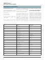
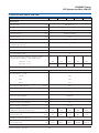
12 Technical Data (400 to 1200 kVA)
UPS Unit
400
600
800
1000
1200
Primary input
Nominal voltage(1)
(V)
400 (3Ph + N(1))
Voltage range
(V)
340 to 460
Minimum voltage without battery discharge(10)
(V)
250
Nominal frequency
(Hz)
50 (60 selectable)
Frequency range
(Hz)
± 10%
ⱖ 0.99
Power factor @ nominal load & nominal input conditions(2)
Input current distortion @ nominal input conditions(2)
& nominal output power(3)
(%)
<3
Walk in/Soft start (seconds)
10 (1 to 90 selectable)
Rectifier Hold-Off (seconds)
1 (1 to 180 selectable)
Inrush current/Imax input(4)
ⱕ1
AC/DC rectifier efficiency without charging current
@ nominal input conditions(2) with resistive load:
- Half load(7) ⱖ (%)
97.6
97.8
97.8
97.8
97.8
- Full load(7) ⱖ (%)
97.5
97.7
97.7
97.7
97.7
BATTERY
Permissible battery voltage range
(V)
396 to 700
Recommended no. of cells:
- VRLA(5)
240
- WET
240
- NiCd
375
Float voltage for VRLA @ 20°C(6)
(V/cell)
2.27
End cell voltage for VRLA
(V/cell)
1.65
Float voltage temperature compensation
-0.11% per °C
DC ripple current in float mode for a 10 min
autonomy as per VDE0510(5)
<0.05C10
Float Voltage stability in steady state condition
(%)
ⱕ1
DC ripple voltage without battery
(%)
ⱕ1
Optimum battery temperature
(°C)
15 to 25
Maximum Battery recharge current for 240 cells
@ 400V input voltage & nominal load
Battery output power in discharge mode with
nominal output load
(A)
140
210
280
350
420
(kW)
377
565
754
942
1130
1902.9
2378.6
End battery voltage for 240 cells
(V)
End battery current for 240 cells with
nominal output load.
(A)
MKA4CAT0UKTRIN/Rev 1-09/2009/UK
396
475.7
18
951.4
1427.1
CHLORIDE Trinergy
UPS Systems from 200 to 1200 kVA
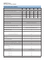
12 Technical Data (400 to 1200 kVA)
UPS Unit
400
600
800
1000
1200
Inverter Output
Apparent nominal power @ 40°C ambient
(kVA)
400
600
800
1000
1200
Apparent nominal output power @ 25°C ambient
(kVA)
440
660
880
1100
1320
Nominal active power
(kW)
360
540
720
900
1080
(A)
580
870
1159
1449
1739
(kW)
400
600
800
1000
1200
Nominal output current
Maximum active power up to 100%
of nominal apparent power(10)
Overload at nominal output voltage for 10 minutes
(%)
125
Overload at nominal output voltage for 1 minute
(%)
150
Short circuit current for 10ms/ <5s
(%)
300/150
(V)
400 (380/415 selectable, 3ph+N)
Nominal output frequency
(Hz)
50 (60 selectable)
Voltage stability in steady state condition for input
(AC & DC) variations and step load (0 to 100%)
(%)
±1
Nominal output voltage
Voltage stability in dynamic condition for input variation
(AC & DC) and step load (0 to 100% and vice versa) (%)
Voltage stability in steady state for 100%
load imbalance (0, 0, 100)
Complies with IEC/EN 62040-3, Class 1
(%)
±3
- synchronised with bypass mains
(%)
±1 (2, 3, 4 selectable)
- synchronised with internal clock
(%)
±0.1
Output frequency stability
Frequency slew rate
(Hz/sec)
<1
Output voltage distortion with 100%
linear load
(%)
<1
Output voltage distortion @ reference non linear
load as for IEC/EN 62040-3
(%)
<3
Load crest factor handled without derating the ups (Ipk/Irms)
3:1
Phase angle precision with balanced loads
(degrees)
1
Phase angle precision with 100% unbalanced loads (degrees)
<3
DC/AC Inverter efficiency @ nominal input conditions(2)
with resistive load:
- Half load(7) ⱖ (%)
97.7
- Full load(7) ⱖ (%)
97.6
Neutral conductor sizing
1.7 nominal current
Output power upgrading with ambient temperature:
- At 25°C (%)
110
- At 30°C (%)
105
- At 40°C (%)
100
19
MKA4CAT0UKTRIN/Rev 1-09/2009/UK
CHLORIDE Trinergy
UPS Systems from 200 to 1200 kVA
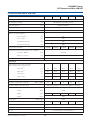
12 Technical Data (400 to 1200 kVA)
UPS Unit
400
600
800
1000
1200
Static bypass
(V)
400 (380/415 selectable, 3ph+N)
Nominal frequency
(Hz)
50/60 (selectable)
Frequency range
(%)
±1 (2, 3, 4 selectable)
Voltage range
(%)
±10
- For 10 minutes
(%)
125
- For 1 minute
(%)
150
- For 600 milliseconds
(%)
700
- For 100 milliseconds
(%)
1000
Nominal bypass voltage(1)
Maximum overload capacity
I2t @ Tvj=125°C 8.3-10ms
(A2s)
1280000
2880000
5120000
8000000
11520000
Transfer time with inverter synchronous to bypass:
- Inverter to Bypass
(ms)
no break
- Bypass to Inverter
(ms)
no break
(ms)
<20
Transfer time with inverter not synchronous to Bypass
System data
AC/AC efficiency VFI mode @ nominal
input conditions(2) with resistive load:
- 25% load(7)(8)
(%)
95
95.2
95.2
95.2
95.2
- 50% load(7)(8)
(%)
95.4
95.6
95.6
95.6
95.6
- 75% load(7)(8)
(%)
95.5
95.7
95.7
95.7
95.7
- 100% load(7)(8)
(%)
95.2
95.5
95.5
95.5
95.5
AC/AC Efficiency VFD mode(7)
(%)
75
76
Noise @ 1 metre as per ISO 3746
99
(dBA ± 2dBA)
71
Protection degree with open doors
73
74
IP20 (higher degree of protection available on request)
Mechanical dimensions:
- Height
(mm)
- Width
(mm)
- Depth(9)
(mm)
860
(RAL scale)
5004
Frame colour
Weight
1780
1800
(kg)
1450
Cable entry
2775
2370
3450
3040
4450
5125
3890
4560
Top/Bottom
Access
Front
Cooling
Forced Ventilation with redundancy
MKA4CAT0UKTRIN/Rev 1-09/2009/UK
20
CHLORIDE Trinergy
UPS Systems from 200 to 1200 kVA
12 Technical Data (400 to 1200 kVA)
UPS Unit
400
600
800
1000
1200
Environmental
Operating temperature(11)
(°C)
0 - 40
Maximum relative humidity @ 20°C (non condensing)
(%)
up to 95
Max altitude above sea level without derating
(m)
1000 (for higher altitudes complies with IEC/EN 62040-3)
(1) In case of a split bypass configuration primary input and bypass mains must have a common earth. The neutral conductor could be part of the bypass or
primary mains but it must be present.
(2) At nominal voltage, nominal frequency.
(3) With input voltage at nominal value and with THDv 1%.
(4) Imax input can be calculated using the maximum input power @400V in recharge mode.
(5) Permitted number of cells = 240 – 300. Special battery cabinet for more than 240 cells.
(6) There are several possible charging methods. Refer to chapter 5 for full description.
(7) For tolerance see IEC/EN 60146-1-1 or DIN VDE 0558.
(8) Efficiency referred to VFI mode with Circular Redundancy.
(9) Including front handle; without handle 830 mm.
(10) Conditions apply. For further details please contact technical support.
(11) Reccomended average daily ambient temperature 35°C with a maximum of 40°C for 8 hours as requested by 62040 standard.
General conditions for the Technical Data table:
The data shown are typical and not definable in other ways; furthermore the data refer to 25°C ambient temperature and PF= 1 where not specified.
Not all the data shown apply simultaneously and may be changed without prior warning.
Data apply to the standard version, if not otherwise specified.
If the options described in chapter 13 are added, the data shown in the Technical Data Table may vary. For test conditions and measurement tolerances not
specified in the table refer to the Witness Test Report procedure.
13 Options
13.1 Isolation transformer
Trinergy can be customised to provide
full galvanic isolation for specific load
requirements by adding an external
isolation transformer. For further detail
please contact the technical support.
These options will provide the following
benefits:
• Full galvanic isolation for medical and
“most critical” applications
• Installation with two independent
input sources with different neutrals
• Installation in distribution without
neutral
• Voltage adaptation
13.2 Core Connection Kit
In order to add one power module to the
existing configuration it is necessary to
fit the copper bar present on the back
of the unit which connects input output
and bypass of the power module to
the central I/O Box. Six different
connection kits are available to suit
the module(s) installed.
The interconnection kit for the first
module to be connected to the left and
to the right of the I/O Box also contains
the side panel of the power module.
13.4 Remote Display
A remote alarm panel will be available
to display important messages from
the individual UPS. Upon request, it
will be possible to display up to
eight UPS systems.
13.3 Parallel configurations
Trinergy can be connected with up
to eight units in parallel, without the
need for an additional parallel board,
allowing maximum reliability and
flexibility.
A single unit can be upgraded to a
parallel one at any time through a
parallel
cable
used
for
the
communication between the UPS
connected in parallel. One parallel
cable kit is required for each unit to be
paralleled.
21
MKA4CAT0UKTRIN/Rev 1-09/2009/UK
CHLORIDE Trinergy
UPS Systems from 200 to 1200 kVA
13 Options
13.6 Battery management modules
(only upon request)
13.9 MopUPS shutdown
monitoring software
With measuring modules connected to
the battery blocks, enhanced battery
management will be possible offering the
following features:
The main function of MopUPS
software will be the safe shutdown of
the operating system in the event of a
power failure. Other functions include:
• Measurement of the condition of
each individual battery block by
means of separate battery measuring
modules (BMM)
• Analysis of each battery block with
measurement of the minimum and
maximum voltage values.
13.7 Dust filters
This option will improve the protection
degree of the air entrance from IP20 to
lP40 for specific applications such as
a dusty environment. The filter will be
housed in the UPS cubicle (IP20).
1.
2.
3.
4.
5.
and
Automatic communications for
events; e-mail, SMS, etc.
File saving of event log and status
information
Viewing and monitoring of UPS in
real time
Programmed system shutdown
Remote monitoring of UPS
connected to network server using
Named Pipes or TCP/IP
13.10 ManageUPS adapter
This option will include a complete
package (including slot card adapter) to
ensure monitoring and control of the
networked UPS through TCP/IP
protocol. The adapter permits:
13.8 Use as frequency converter
Trinergy may be programmed for use as a
frequency converter (50Hz in - 60Hz out
or 60Hz in -50Hz out) for operations with
or without a battery bank connected.
In this operational mode, the data shown
in the Technical Data table may vary (e.g.
output overload capability). Please
contact Chloride Technical Support for
details.
MKA4CAT0UKTRIN/Rev 1-09/2009/UK
• UPS monitoring from NMS via
SNMP
• UPS monitoring from PC via a Web
browser
• Dispatch of e-mail messages on
occurrence of events
ManageUPS, in conjunction with
MopUPS, will also permit safe
shutdown of the operating systems.
22
13.11 MODBUS RTU / JBUS and
Environment Sensor
Two
special
versions
of
the
ManageUPS NET adapter are available
for Trinergy and include the following
added options:
• The ManageUPS NET Adapter + B
series which provides an open
approach to the management of
the network power. ManageUPS +
B simplifies the integration of
Chloride UPS systems with
Building Monitoring and Automation
Systems via MODBUS RTU,
MODBUS/TCP or JBUS protocols.
• ManageUPS NET Adapter + E
model includes the auxiliary Blue
Bus connector, one (1) Environment
Sensor module and a five-meter
Blue Bus cable. The Environment
Sensor measures the ambient
temperature and relative humidity
(RH), reads three (3) volt-free relay
input contacts and controls one (1)
output relay for event response.
It is also possible to add a cascade
of up to 16 additional sensor
modules to monitor multiple
zones from one UPS network
adapter. Flexible "Any or All" logic
allows you to pick multiple event
triggers to drive the output relay
control.
CHLORIDE Trinergy
UPS Systems from 200 to 1200 kVA
Appendix: Planning and Installation
Installation site
Pay attention to
conditions when
installation site:
Avoid
the following
selecting an
• This UPS must only be installed in
closed operating areas. If the area
houses, any equipment containing
in excess of 25 litres of inflammable
fluids, refer to HD 384.4.42 S1 A2,
chapter 42 (corresponds to DIN
VDE 0100, Part 420), it must be
ensured that flammable fluids and
or combustive products cannot
spread through the building.
• The ambient temperature should
be between 0°C and +40°C for
UPS devices. Continuous operation
at temperatures up to a maximum
of +50°C, reduces the max. load
by 12% of the nominal load per
5°C.
• The ambient temperature should
be between +15°C and +25°C for
batterycabinets.
• Be sure to provide sufficient cooling
of the installation room so that the
ambient temperature remains within
the stated limits. The heat emission
ratings of the UPS are given in the
Technical Data tables. Be sure also to
provide sufficient ventilation for the
type of batteries used in the UPS.
• When operating the Trinergy UPS at
altitudes over 1000m a.s.l., the load
must be reduced accordingly (see
User Handbook). If the ambient
temperature remains less than
+30°C, no load reduction is necessary
for altitudes up to 2000m.
• Ensure that the load carrying capacity
of the floor is sufficient for the UPS
and batteries. The floor must be even
and level.
23
harmful
agents
such
as:
• Vibration, dust, corrosive atmospheres
and high humidity
Allow the following min. distances:
• 500 mm between the top of the
cabinet and the roof
• No wall-distance is required, unless
the cables are routed from above,
in which case the wall-distance
must be at least equal to the
bending radius of the cables in use.
The distance between covering
parts and floor is 150 mm.
• No limits on either side of device.
MKA4CAT0UKTRIN/Rev 1-09/2009/UK
CHLORIDE Trinergy
UPS Systems from 200 to 1200 kVA
Notes
MKA4CAT0UKTRIN/Rev 1-09/2009/UK
24
Chloride Systems
WORLD HEADQUARTERS
Via Fornace 30
40023 Castel Guelfo (BO)
Italy
T +39 0542 632 111
F +39 0542 632 120
E [email protected]
www.chloridepower.com
Chloride operates through a worldwide network of Chloride sales and service offices and
joint ventures, with operations across 80 countries including:
Almaty, Kazakhstan
Bangkok, Thailand
Beijing, China
Makati City, Philippines
Bologna, Italy
Buenos Aires, Argentina
Chicago, USA
Dubai, UAE
Erlangen, Germany
Ho Chi Minh City, Vietnam
Lisbon, Portugal
Istanbul, Turkey
Madrid, Spain
Moscow, Russia
Paris, France
Pune, India
Diadema, Brazil
Shanghai, China
Singapore
Southampton, UK
Sydney, Australia
Warsaw, Poland
• Principal sales & service offices
• Service network
Chloride Middle East
Arenco Tower, Office 608
Dubai Internet City - Dubai
UAE
PO Box 72536
Chloride Secure Power Philippines, Inc.
28th Floor, Tower 2, The Enterprise Center
6766 Ayala Avenue corner Paseo de Roxas
Makati City 1226
Philippines
CHLD Singapore Pte Ltd
2 Corporation Road
#03-07 Corporation Place
Singapore
618494
T +61 2 9888 1266
F +61 2 9888 1966
E [email protected]
T +971 4 434 5201
F +971 4 430 8032
E [email protected]
T +632 849 3895
F +632 886 5008
E [email protected]
T +65 6481 4776
F +65 6481 0552
E [email protected]
www.chloridepower.com.au
www.chloridepower.com/middle-east
www.chloridepower.com
www.chloridepower.com.sg
Chloride UK
George Curl Way
Southampton
Hampshire, SO18 2RY
United Kingdom
Chloride North America
27944 North Bradley Road
Libertyville, IL 60048
USA
Chloride Power Protection Limited
1093/98-99 M. 12 Central City Tower 1
18th floor, Bangna-Trad Road (K.M.3)
Bangna, Bangkok 10260
Thailand
T +44 (0) 23 8061 0311
F +44 (0) 23 8061 0852
E [email protected]
T +1 847 816 6000
+1 800 327 8801
F +1 847 680 5124
E [email protected]
www.chloridepower.co.uk
www.chloridepower.com/usa
T +66 2762 3600
F +66 2745 6618
E [email protected]
www.chloridepower.com/th
For a full list of contacts please visit our website at www.chloridepower.com
Chloride Vietnam
Unit 1708, 17th Floor, Gemadept Tower
06 Le Thanh Ton Street
Ben Nghe Ward, District 1
Ho Chi Minh City
Vietnam
T +84 8 255 6737
F +84 8 255 6800
www.chloridepower.com/vn
MKA4CAT0UKTRIN
Chloride Australia
Ground Floor, 16 Giffnock Avenue
North Ryde
NSW 2113
Australia