1
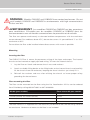
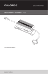
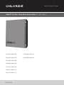
Secure Power Always
ONEAC® FA Filter Three-Phase Power Filter (30 - 200 Amps)
FA23030 (026-005)
FA43200 (026-012)
FA63030 (026-075)
FA63200 (026-078)
FA23060 (026-060)
FA63060 (026-076)
FA23100 (026-070)
FA63100 (026-077)
FA23200 (026-011)
User manual
Secure Power Always
FA Series Power Filter
Introduction
Thank you for selecting this Chloride product. This ONEAC brand power filter offers reliable
protection from the harmful effects of electrical line disturbances.
Registering your product
To register your FA Power Filter, please complete the warranty registration card included with
your filter or online at www.chloridepower.com/usa. From the product page, go to product
registration.
About this manual
Important safety instructions
Save these instructions.
Please read and save these instructions. This manual contains important instructions for the
ONEAC FA Power Filter. Follow these instructions during the unpacking, installation, and
maintenance of the filter. If you have a problem with the filter, please refer to this manual
before calling Technical Services.
Technical Services
Chloride offers 24-hour technical support. To contact technical services:
North America: toll free (800) 327-8801 (Opt 3),
local (847) 816-6000 (opt 3)
email:
[email protected]
Please check with Technical Services before attempting to return any Chloride product under
warranty. If a Chloride product needs repair or replacement, Technical Services issues a Return
Material Authorization (RMA) number along with instructions on how to return the product.
Dangerous voltages are present within this unit. There are no user serviceable parts within this
unit; therefore, any repairs or modifications may result in out-of-warranty repair charges, unsafe
electrical conditions, or violation of electrical code.
Sizing information
The rating label of your filter is located on the inside of the door. The rating label lists the FA
model’s current rating, nominal input and output voltage and serial number. Verify that the voltage
and current specified on the rating label are appropriate for your application. The combined steady
state RMA current draw of all your equipment must not exceed the filter’s output current rating
on any of the three phases.
Introduction
1
FA Series Power Filter
2
Introduction
Secure Power Always
FA Series Power Filter
Contents
Introduction...........................................................................................................................1
Registering your product..................................................................................................1
About this manual.............................................................................................................1
Technical Services............................................................................................................1
Sizing information.............................................................................................................1
Installation.............................................................................................................................5
Installation overview.........................................................................................................5
Important installation guidelines.......................................................................................5
Verifying your installation..................................................................................................7
Installation and operation.......................................................................................................8
Unpacking and placement................................................................................................8
Mounting..........................................................................................................................9
Main input fuses.............................................................................................................10
Input and output connections.........................................................................................11
Component identification....................................................................................................14
Component identification...............................................................................................15
Filter disposal.......................................................................................................................17
Specifications......................................................................................................................18
Physical views.....................................................................................................................24
Fuse and suppressor replacement......................................................................................28
Fuse replacement...........................................................................................................28
Fault diagnosis................................................................................................................29
Troubleshooting an installation............................................................................................33
Warranty..............................................................................................................................34
Limitations of warranty...................................................................................................34
Exclusive remedies.........................................................................................................34
Return procedure............................................................................................................34
Introduction
3
FA Series Power Filter
4
Introduction
Secure Power Always
FA Series Power Filter
Installation
Installation overview
NOTE: Only qualified electricians should install an ONEAC FA Filter.
Follow the National Electrical Code®, local codes, good wiring practice and the user
manual.
1. Unpack the filter. See “Unpacking and placement” on page 8.
2. Position the filter correctly within the enclosure.
3. Mount the filter at the installation location and punch conduit holes for the input and
output. See “Mounting” on page 9.
4. Connect the input wires. See “Input and output connections” on page 11.
Connect the ground connection first. Use a grounding conductor that is equal to or
larger than the current carrying conductors.
5. Verify the correct operation of the filter. See “Verifying your installation” on page 7.
6. Connect your equipment to the output. See “Input and output connections” on page
11.
Use steel wall conduit or steel flexible conduit with a continuous copper ground.
Do not connect a neutral wire to the output of a delta connected unit.
7. Turn on the equipment protected by this filter.
8. Start normal operation of your system.
Important installation guidelines
CAUTION: RISK OF ELECTRIC SHOCK —EXPOSED LIVE PARTS. Switch off
at power source and wait ten seconds before removing or replacing components.
Installation and maintenance to be carried out by qualified electrician.
ATTENTION: RISQUE D’ÉLECTROCUTION - PARTIES VIVANTES EXPOSÉES.
Éteignez la source d’alimentation et attendez 10 secondes avant d’enlever ou de
remplacer des composantes. L’installation et l’Entretien doivent être réalisés par
un électricien certifié.
Installation
5
FA Series Power Filter
WARNING:
Only qualified electricians should install or retrofit this filter.
This filter contains DANGEROUS VOLTAGES.
Accidental contact can result in serious electrical shock.
High leakage current.
Ground connection is ESSENTIAL before connecting supply.
ATTENTION:
Seulement les électriciens qualifiés devraient installer ou mettre à niveau ce
filtre.
Ce Filtre contient des VOLTAGES DANGEREUX.
Le contact accidentel peut entrainer un choc électrique majeur.
Fort courant de fuite.
Le branchement de la mise à la terre est essentiel avant la mise en servce.
Always follow the National Electrical Code® or your local electrical codes and good wiring
practice.
This filter is three-phase and wired in a “DELTA TO DELTA” or a “WYE TO WYE”
configuration. See figure below.
6
Installation
Secure Power Always
FA Series Power Filter
fig. 1. Wiring circuit for the FA Three-Phase Power Filter
NOTE: DO NOT connect a neutral wire to the output of a “delta to delta” configuration.
Physically separate the input power connections to the filter from the equipment power
connections on the output.
Data cables should be kept as far away as possible from any power cables.
For maximum performance:
• Use steel wall conduit or flexible steel conduit with a continuous copper ground
between your equipment and the filter.
• Always include a ground wire for each circuit on the output of the filter. DO NOT use
an extension cord or power strips.
• DO NOT connect your equipment to the filter’s output until the input connections
have been made and proper filter operation has been verified.
Verifying your installation
1. Turn off the branch circuit feeding the filter. Verify that the installation follows the
guidelines outlined in section entitled “Important installation guidelines” on page 5.
2. Turn on the main power source.
CAUTION: DANGEROUS VOLTAGES ARE PRESENT.
ATTENTION: PRÉSENCE DE VOLTAGE DANGEREUX.
3. Use a voltmeter to determine if voltage is present at the input and output terminals.
Installation
7
FA Series Power Filter
4. If the operating voltage matches that suggested by the device manufacturer, turn on
the equipment and operate as usual.
If the variation is greater than the manufacturer’s specifications on any phase, a tap
selection for that phase should be made to adjust the voltage level.
If there is power at the input with no power at the output, turn off the branch circuit
feeding the filter and follow the procedure in the section titled “Troubleshooting an
installation” on page 33.
Installation and operation
Unpacking and placement
Your ONEAC FA Power Filter is delivered on a wooden pallet. Upon arrival, inspect the unit
and pallet for signs of damage. Examine the encloser for dents or scratches and open the
door to check for loose or broken parts.
If damage is detected, immediately contact the freight company and Chloride Technical
Services. Chloride Technical Services can be reached at (800) 327-8801 (Opt 3) or (847) 816
6000.
Chloride recommends that your filter be left on the pallet during handling. Remove the filter
from the pallet once it is as close to the final installation location as possible.
The actual physical placement of the filter should be as close as possible to the equipment
being protected. The filter should be installed inside the room containing the equipment
being protected. Consideration should be given to ease of access to the equipment and
the conduit entry points. If the standard wall-mounting is not appropriate, an optional floor
mounting kit is available.
Adequate ventilation is essential to prevent overheating, which could result in unnecessary
operation of the main fuses. There should be at least six inches (150 mm) of unrestricted
space at the top, bottom, and sides of the enclosure.
8
Installation and operation
Secure Power Always
FA Series Power Filter
WARNING: Models FA43200 and FA63200 have vented enclosures. Do not
install models FA43200 and FA63200 in environments with high concentrations
of dust and dirt.
AVERTISSEMENT: Les modèles FA43200 et FA63200 ont des ouvertures
pour ventilations. N’installez pas les modèles FA43200 et FA63200 dans les
evnironnements avec de hautes concentrations de poussière et de saletés.
The filter can operate continuously at elevated ambient temperatures with the maximum
current derated. For ambients above 25°C, derate the current 1% per additional °C to -15%
maximum at 40°C.
Do not allow the filter to be installed where direct contact with water is possible.
Mounting
Inverting the filter
The ONEAC FA Filter is meant for permanent wiring of the input and output. The internal
chassis can be inverted to supply top feed wiring. To invert the internal chassis:
1. Lay the filter on it back and remove the six nuts and washers.
2. Attach a suitable lifting device to the lifting holes on the internal chassis and carefully
lift the chassis from the enclosure, keeping the chassis level as you slowly lift it.
3. Reinstall the washers and nuts after refitting the chassis to insure proper safety
grounding for the enclosure.
Floor mounting the filter
The filter can be mounted on the floor using the kits listed below. All kits can be ordered
from Chloride by calling 800-327-8801 or 847-816-6000.
Model (part number)
Floor-mount kit part number
FA23030 (026-005) and FA63030 (026-075)
350-091
FA23060 (026-060) and FA63060 (026-076)
350-073
FA23100 (026-070) and FA63100 (026-077)
350-046
FA23200 (026-011), FA43200 (026-012), and FA63200 (026-078)
350-064
The floor mount kit is supplied with the necessary hardware to bolt the mounting stand to
the enclosure. Hardware to mount to the floor is not included.
Installation and operation
9
FA Series Power Filter
WARNING: Cover all the electrical components to protect from debris before
using the floor mount template to mark and drill the necessary holes. Failure to do
so may cause a serious electrical hazard.
AVERTISSEMENT: Couvrez toutes les composantes électriques pour
protéger des débris avant de marquer et forer les trous nécessaires à l’installation.
Ignorer cet avis peut entrainer de sérieux problèmes électriques.
Once the location of your filter has been determined, permanetly bolt the enclosure in place.
If the mounting is not flat, the door may not open and close properly. If the top of the door
strikes the lip which extends around the body opening, place metal shims between the
mounting at the bottom of the enclosure and closest to the door hinge. Be sure all mounting
screws are tight.
Main input fuses
This feature is needed to protect your equipment and the ONEAC FA Power Filter. The branch
circuit feeding the filter should have ratings which meet or exceed the fuses within the filter.
Time-delay fuses are supplied as the main fuses within the filter. This allows for equipment
with large inrush and surge current characteristics. Should this feature be required for your
equipment, the branch circuit protective device(s) should also be suitably rated.
The ONEAC FA Power Filter’s main input fuses can be replaced using the fuses listed below.
Three fuses are needed for each filter.
Model
FA23030
Fuse description
30 A, 250 V time delay
Manufacturer part number
Bussman
Littelfuse
Gould
Shawmut
Reliance
FRN-R-30
FLN-R-30
TR 30 R
ECNR 30
FA36060
30 A, 600 V time delay
FRS-R-30
FLS-R-30
TRS 30 R
ECSR 30
FA23060
75 A, 250 V time delay
FRN-R-75
FLN-R-75
TR 75 R
ECNR 75
FA63060
75 A, 600 V time delay
FRS-R-75
FLS-R-75
TRS 75 R
ECSR 75
FA23100
150 A, 250 V time delay
FRN-R-150
FLN-R-150
TR 150 R
ECNR 150
FA63100
150 A, 600 V time delay
FRS-R-150
FLS-R-150
TRS 150 R
ECSR 150
FA23200
200 A, 250 V time delay
FRN-R-200
FLN-R-200
TR 200 R
ECNR 200
FA43200
200 A, 600 V time delay
FRS-R-200
FLS-R-200
TRS 200 R
ECSR 200
FA63200
200 A, 600 V time delay
FRS-R-200
FLS-R-200
TRS 200 R
ECSR 200
10
Installation and operation
Secure Power Always
FA Series Power Filter
Input and output connections
This product is meant for permanent wiring of the input and output.
Use the template provided to mark suitable locations for input and output conduits adjacent
to the terminals—top, bottom, or through the rear of the enclosure.
CAUTION: Do not fit conduits to any other face of the enclosure. Before
proceeding, turn off the main power source supplying the filter at the service
disconnect.
ATTENTION: Ne pas installer de conduit sur un autre côté. Avant de
commencer, éteignez la source d’alimentation principale alimentant le filtre.
WARNING: Cover all electrical components before punching conduit holes.
Debris around the electrical components may cause a serious electrical hazard.
AVERTISSEMENT: Couvrez toutes les composantes électriques avant de
perforer les trous de conduit. Les débris autour des composantes électriques
peuvent provoquer de sérieux problèmes électriques.
Remove paint from around the hole on the inside of the enclosure to ensure good grounding
of the conduit.
Install an appropriate conduit and fitting for the application.
Cable styles and minimum wire sizes should be appropriate for the current rating of the
equipment, as defined by local and national regulations. Take into account any derating which
may be necessary for special conditions. All installation practices shall be in accordance with
such regulations.
UL Lised connectors are recommended for wiring connections on the input and output.
Connectors with two holes are recommended for models FA23200, FA43200, and
FA63200.
Use copper conductors only. Strip the insulation from the wire.
Ensure that all insulation is removed, that the conductors are clean with no conductor strand
cut through, and that the stranding remains neatly twisted.
Use compression tools and dies suitable for the wire size and terminal used.
Installation and operation
11
FA Series Power Filter
Ensure that the conductor reaches the end of the crimp barrel.
A well crimped terminal will have a smooth polished appearance where the die has
compressed the terminal barrel. The crimped portion will match the shaped of the dies
exactly (especially the angles), but there will not be excessive amounts of “flash” where
the dies meet.
Use screws, bolts, and washers suitable for the terminals used. Connect the terminals to
the terminal bars.
Phase rotation sequence is maintained by the ONEAC FA Filter. Using both mounting holes
for models FA23200, FA43200, and FA63200.
Connect the input ground to the terminal block (G).
Heavy gauge wire, equal to or larger in diameter than the power carrying conductors should
be used to connect the safety ground.
It is recommended that ground be wired back to the service ground.
WARNING: Do not rely on the conduit alone for the connection to the ground.
This filter may have high leakage current.
AVERTISSEMENT: Ne pas se fier uniquement sur le conduit pour la
connexion de la mise à la terre. Ce filtre peut avoir un courant de fuite élevé.
Chloride discourages the down sizing of grounding conductors as allowed by various codes.
If in doubt regarding wiring sizing, consult the National Electrical Code®, Table 310-16, or
your local electrical code.
Connect the input phase wires to the input terminals, torquing each connection. Refer to
the following chart for the torque specifications.
Follow the procedure in the “Verifying your installation” section on page 7.
The following table shows the recommended safe working torque specifications for the FA
Power Filter.
12
Installation and operation
Secure Power Always
FA Series Power Filter
Bolt/Screw size
1/2” (12 mm)
Stainless steel
45 ft/lbs
61 Nm
Brass
35 ft/lbs
47 Nm
7/16” (11 mm)
33 ft/lbs
44 Nm
26 ft/lbs
35 Nm
3/8” (9 mm)
21 ft/lbs
28 Nm
16 ft/lbs
21 Nm
5/16” (8 mm)
138 in/lbs
15 Nm
107 in/lbs
12 Nm
1/4” (6 mm)
79 in/lbs
9 Nm
62 in/lbs
7 Nm
#10
24 in/lbs
2.5 Nm
19 in/lbs
2 Nm
#8
21 in/lbs
2 Nm
16 in/lbs
1.5 Nm
#6
10 in/lbs
1 Nm
8 in/lbs
1 Nm
#4
5.5 in/lbs
0.5 Nm
4.3 in/lbs
0.5 Nm
Component identification
13
FA Series Power Filter
Component identification
The ONEAC FA Power Filter’s major components are outlined in the drawing below. The
actual component location may differ depending on the filter model and/or the power feeder
location (for example, top feed).
Refer to the section “Fuse and suppressor replacement” on page 28 for fuse values for your
model filter. Some components can be replaced by a qualified electrician on site and other
can only be retrofitted by Chloride Technical Services on site or installed at the factory.
NOTE: Field retrofitting requires that your system power be shut down.
14
Component identification
Secure Power Always
FA Series Power Filter
Component identification
fig. 2. Component identification FA23030 and FA63030
Component identification
15
FA Series Power Filter
fig. 3. Component identification for FA23060, FA63060, FA23100, and FA63100
16
Component identification
Secure Power Always
FA Series Power Filter
fig. 4. Component identification for FA23200, FA43200, and FA63200
Filter disposal
Once your filter has reached the end of its useful life and it is necessary to dispose of the
unit.
Do not discard waste electrical or electronic equipment (WEEE) in the trash. For
proper disposal, contact your local recycling/reuse or hazardous waste center.
Dispose of the unit in accordance with local/national recycling or disposal ordinances.
Filter disposal
17
FA Series Power Filter
Specifications
FA Power Filter model
FA23030
FA63030
FA23060
FA63060
Part number
026-005
026-075
026-060
026-076
Load current rating (Amps/phase)*
30
30
60
60
Frequency (Hz)
50/60
50/60
50/60
50/60
Enclosure rating**
NEMA 12
NEMA 12
NEMA 12
NEMA 12
Physical
Dimensions (with bracket) HxWxD - in (mm)
24 x 16 x 9 (610 x 410 x 230)
30 x 20 x 9 (760 x 510 x 230)
Floor footprint - sq in (sq cm)
144 (943)
180 (1173)
Ship weight - lbs (kg)
85 (39)
150 (68)
RF 50 Ω insertion loss (line to load; load to line)
400 kHz to 4 MHz (typical)
100 kHz to 10 MHz (typical
30 kHz to 30 MHz (typical)
45 db
35 db
35 db
45 db
35 db
35 db
45 db
35 db
35 db
45 db
35 db
35 db
1 kHz forward transfer impedance (Ω)
< 1.0
< 1.0
< 1.0
< 1.0
Efficiency at rated load (%)
> 98
> 98
> 98
> 98
Load power factor range (crest factor)
0.3 leading to 0.3 lagging
Surge voltage withstand capability
ANSI/IEEE C62.41 Cat A & B, 6 kV/200 & 500 A,
100 kHz ringwave and impulse
Clamping response time, normal and common modes
instantaneous
Surge voltage let-through (max) when subject to 6 kV
ANSI/IEEE C62.41 Cat. A test
less than 20 V normal mode (L-N), less than 20 V common
mode (L-G)
Overload capability (typically tolerated without
degradation
20 times rated output for 0.5 cycle
7.5 times rated output for 1 second
5 times rated output for 10 seconds
Distortion
< 1% THD added into a resistive load
Load regulation response time
< 2 msec for a 50% change in load
Interruption response time
Output voltage will track input voltage in less than 2 msec
at power-off and power-on for a single-cycle asynchronous
notch.
Cooling
convection
Warranty
Five-year materials and workmanship
Operating environment
Temperature
+32°F to +104°F (0°C to +40°C)
Humidity
0-95%, non-condensing
Elevation - ft (m)
10,000 (3000) ASL
Safety listings
Approvals
18
UL, cUL
Specifications
Secure Power Always
FA Series Power Filter
FA Power Filter model
FA23030
FA63030
FA23060
FA63060
Input - output voltage range (3-ph Delta)
190 - 250
380 - 600
standard
NA
NA
standard
standard
NA
NA
standard
Input - output voltage range (3-ph Wye)
190/110 - 250/144
380/220 - 600/346
standard
NA
NA
standard
standard
NA
NA
standard
Input and output termination (hardwired - internal)
standard
standard
standard
standard
Main fuse kit
optional
optional
optional
optional
Suppressor fuse kit
optional
optional
optional
optional
Floor mounting kit
optional
optional
optional
optional
Features and options
Specifications
19
FA Series Power Filter
FA Power Filter model
FA23100
FA63100
Part number
026-070
026-077
100
Load current rating (Amps/phase)*
100
Frequency (Hz)
50/60
50/60
Enclosure rating**
NEMA 12
NEMA 12
Physical
Dimensions (with bracket) HxWxD - in (mm)
30 x 24 x 13 (762 x 610 x 330)
Floor footprint - sq in (sq cm)
312 (2013)
312 (2013)
Ship weight - lbs (kg)
210 (95)
210 (95)
RF 50 Ω insertion loss (line to load; load to line)
400 kHz to 4 MHz (typical)
100 kHz to 10 MHz (typical
30 kHz to 30 MHz (typical)
50 db
40 db
30 db
50 db
40 db
30 db
1 kHz forward transfer impedance (Ω)
< 1.0
< 1.0
Efficiency at rated load (%)
> 98
> 98
Load power factor range (crest factor)
0.3 leading to 0.3 lagging
Surge voltage withstand capability
ANSI/IEEE C62.41 Cat A & B, 6 kV/200 & 500 A,
100 kHz ringwave and impulse
Clamping response time, normal and common modes
instantaneous
Surge voltage let-through (max) when subject to 6 kV
ANSI/IEEE C62.41 Cat. A test
less than 20 V normal mode (L-N)
less than 20 V common mode (L-G)
Overload capability (typically tolerated without
degradation
20 times rated output for 0.5 cycle
7.5 times rated output for 1 second
5 times rated output for 10 seconds
Distortion
< 1% THD added into a resistive load
Load regulation response time
< 2 msec for a 50% change in load
Interruption response time
Output voltage will track input voltage in less than
2 msec at power-off and power-on for a singlecycle asynchronous notch.
Cooling
convection
Warranty
Five-year materials and workmanship
Operating environment
Temperature
+32°F to +104°F (0°C to +40°C)
Humidity
0-95%, non-condensing
Maximum elevation - ft (m)
10,000 (3000) ASL
Safety listings
Approvals
20
UL, cUL
Specifications
Secure Power Always
FA Series Power Filter
FA Power Filter model
FA23100
FA63100
Input - output voltage range (3-ph Delta)
190 - 250
380 - 600
standard
NA
NA
standard
Input - output voltage range (3-ph Wye)
190/110 - 250/144
380/220 - 600/346
standard
NA
NA
standard
Features and options
Input and output termination (hardwired - internal)
standard
standard
Main fuse kit
optional
optional
Suppressor fuse kit
optional
optional
Floor mounting kit
optional
optional
Specifications
21
FA Series Power Filter
FA Power Filter model
FA23200
FA43200
FA63200
Part number
026-011
026-012
026-078
Load current rating (Amps/phase)*
200
200
200
Frequency (Hz)
50/60
50/60
50/60
Enclosure rating**
NEMA 12
NEMA 12
NEMA 12
Physical
Dimensions (with bracket) HxWxD - in (mm)
36x30x17 (914 x762x430)
41x30x17 (1040x762x430)
Floor footprint - sq in (sq cm)
510 (3268)
510 (3268)
510 (3268)
Ship weight - lbs (kg)
365 (166)
455 (207)
455 (207)
RF 50 Ω insertion loss (line to load; load to line)
400 kHz to 4 MHz (typical)
100 kHz to 10 MHz (typical
30 kHz to 30 MHz (typical)
50 db
40 db
30 db
50 db
40 db
30 db
45 db
35 db
35 db
1 kHz forward transfer impedance (Ω)
< 1.0
< 1.0
< 1.0
Efficiency at rated load (%)
> 98
> 98
> 98
Load power factor range (crest factor)
0.3 leading to 0.3 lagging
Surge voltage withstand capability
ANSI/IEEE C62.41 Cat A & B, 6 kV/200 & 500 A,
100 kHz ringwave and impulse
Clamping response time, normal and common modes
instantaneous
Surge voltage let-through (max) when subject to 6 kV
ANSI/IEEE C62.41 Cat. A test
less than 20 V normal mode (L-N), less than 20 V
common mode (L-G)
Overload capability (typically tolerated without
degradation
20 times rated output for 0.5 cycle
7.5 times rated output for 1 second
5 times rated output for 10 seconds
Distortion
< 1% THD added into a resistive load
Load regulation response time
< 2 msec for a 50% change in load
Interruption response time
Output voltage will track input voltage in less than
2 msec at power-off and power-on for a single-cycle
asynchronous notch.
Cooling
convection
Warranty
Five-year materials and workmanship
Operating environment
Temperature
+32°F to +104°F (0°C to +40°C)
Humidity
0-95%, non-condensing
Maximum elevation - ft (m)
10,000 (3000) ASL
Safety listings
Approvals
22
UL, cUL
Specifications
Secure Power Always
FA Series Power Filter
FA Power Filter model
FA23200
FA43200
FA63200
Input - output voltage range (3-ph Delta)
190 - 250
380 - 480
500 - 600
standard
NA
NA
NA
standard
NA
NA
NA
standard
Input - output voltage range (3-ph Wye)
190/110 - 250/144
380/220 - 480/277
500/288 - 600/346
standard
NA
NA
NA
standard
NA
NA
NA
standard
standard
standard
standard
Termination kit
2 AWG
1/0 AWG
2/0 AWG
4/0 AWG
250 MCM
optional
optional
optional
optional
optional
optional
optional
optional
optional
optional
optional
optional
optional
optional
optional
Main fuse kit
optional
optional
optional
Suppressor fuse kit
optional
optional
optional
Floor mounting kit
optional
optional
optional
Features and options
Input and output termination
(hardwired - internal)
Specifications
23
FA Series Power Filter
Physical views
fig. 5. External view FA23030 and FA63030
24
Physical views
Secure Power Always
FA Series Power Filter
fig. 6. External view FA23060 and FA63060
Physical views
25
FA Series Power Filter
fig. 7. External view FA23100 and FA63100
26
Physical views
Secure Power Always
FA Series Power Filter
.
fig. 8. External view FA23200
Physical views
27
FA Series Power Filter
Maintenance
Maintaining the correct operation of your filter is limited to annually checking the operating
voltage and torquing all the connections.
WARNING: Before proceeding, turn off the power source supplying the filter,
at the service disconnect.
AVERTISSEMENT: Avant de commencer, éteignez la source d’alimentation
alimentant le filtre.
Follow the chart below for recommended safe working torque specifications.
Bolt/Screw size
1/2” (12 mm)
Stainless steel
45 ft/lbs
61 Nm
Brass
35 ft/lbs
47 Nm
7/16” (11 mm)
33 ft/lbs
44 Nm
26 ft/lbs
35 Nm
3/8” (9 mm)
21 ft/lbs
28 Nm
16 ft/lbs
21 Nm
5/16” (8 mm)
138 in/lbs
15 Nm
107 in/lbs
12 Nm
1/4” (6 mm)
79 in/lbs
9 Nm
62 in/lbs
7 Nm
#10
24 in/lbs
2.5 Nm
19 in/lbs
2 Nm
#8
21 in/lbs
2 Nm
16 in/lbs
1.5 Nm
#6
10 in/lbs
1 Nm
8 in/lbs
1 Nm
#4
5.5 in/lbs
0.5 Nm
4.3 in/lbs
0.5 Nm
Fuse and suppressor replacement
The FA Series Power Filter requires fuses in some locations. In the unlikely event that a fuse
needs to be replaced, this section gives the fuse locations and specifications.
Fuse replacement
WARNING: Before proceeding, turn off the power source supplying the filter,
at the service disconnect.
AVERTISSEMENT: Avant de commencer, éteignez la source d’alimentation
alimentant le filtre.
28
Fuse and suppressor replacement
Secure Power Always
FA Series Power Filter
1. Open the filter and locate the fuses.
2. Replace the fuse(s) as needed.
3. Follow the procedure in “Verifying your installation” on page 7.
4. Close the filter.
The ONEAC FA Power Filter’s main input and output suppressor fuses (B and A in each
diagram) can be replaced using the fuses listed below.
Model
Fuse description
Manufacturer part number
Bussman
Littelfuse
Gould
Shawmut
FA23030
10 A, 250 V fast acting
FNM 10
FLM 10
FA63030
10 A, 600 V fast acting
KTK-10
KLK 10
FA23060
10 A, 250 V, fast acting
FNM 10
FLM 10
FA63060
10 A, 600 V fast acting
KTK-10
KLK 10
FA23100
10 A, 250 V fast acting
FNM 10
FLM 10
FA63100
10 A, 600 V fast acting
KTK-10
KLK 10
ATM 10
FA23200 input
15 A, 600 V fast acting
KTK-R-15
KLK-R-15
ATMR 15
FA23200 output
10 A, 250 V fast acting
FNM 10
FLM 10
FA43200 input
15 A, 600 V fast acting
KTK-R-15
KLK-R-15
ATMR 15
FA43200 output
10 A, 600 V fast acting
KTK-10
KLK 10
ATM 10
FA63200 input
15 A, 600 V fast acting
KTK-R-15
KLK-R-15
ATMR 15
FA63200 output
10 A, 600 V fast acting
KTK-10
KLK 10
ATM 10
ATM 10
ATM 10
Fault diagnosis
Blown fuse
Suggested problem
A
output overload
B
failed input suppressor
C
failed output suppressor
NOTE: Equipment may be temporarily operated with failed fuses B and C with reduced protection levels.
Fuse and suppressor replacement
29
FA Series Power Filter
fig. 9. Component identification FA23030 and FA63030
NOTE: The actual physical location of the input and output terminals may differ from what
is shown in the above drawing.
30
Fuse and suppressor replacement
Secure Power Always
FA Series Power Filter
fig. 10. Component identification for FA23060, FA63060, FA23100, and FA63100
NOTE: The actual physical location of the input and output terminals may differ from what
is shown in the above drawing.
Fuse and suppressor replacement
31
FA Series Power Filter
fig. 11. Component identification for FA23200, FA43200, and FA63200
NOTE: The actual physical location of the input and output terminals may differ from what
is shown in the above drawing.
32
Fuse and suppressor replacement
Secure Power Always
FA Series Power Filter
Troubleshooting an installation
Problem
Solution
Power at the input with no power at the output.
1. Turn off the power source supplying the filter at the
main power source or service disconnect.
2. Check the values specified on the nameplates. Verify
that your main power source is correct for the filter’s
input voltage.
3. Use a voltmeter to check continuity of the main line
fuses (A) inside the filter. If any fuses are blown,
replace the main line fuse(s).
Main line fuses (A) blow after being replaced.
1. Turn off the service disconnect
2. Verify the supply requirement.
(A blown main fuse suggests an output overload or incorrect
branch service voltage.)
Branch service protection continually blows.
1. Check the inrush characteristics.
High inrush protection is recommended for both the branch
service and the main line fuses inside the filter.
2. If everything seems correct, disconnect the line and
ground input wires and then contact Chloride Technical
Services.
Chloride offers 24-hour technical support. To contact technical services:
North America: toll free (800) 327-8801 (Opt 3),
local (847) 816-6000 (opt 3)
email:
[email protected]
Please check with Technical Services before attempting to return any Chloride product
under warranty. If a Chloride product needs repair or replacement, Technical Services issues
a Return Material Authorization (RMA) number along with instructions on how to return the
product.
RMAs should be directed to:
Chloride Technical Services
27944 North Bradley Road
Libertyville, IL 60048
Attn: RMA________________
Troubleshooting an installation
33
FA Series Power Filter
Warranty
This Chloride product is warranted to be free from defects in materials and workmanship
for five years. This warranty is limited to repairing or replacing, at Chloride’s option, any
defective component, circuit board, or module contained within the product only when it
is returned with an Chloride Return Material Authorization (RMA) number to Chloride or to
an Chloride-designated repair facility. In all cases, the customer is responsible for shipping
charges to and from Chloride or the Chloride-designated repair facility.
Limitations of warranty
This limited warranty does not cover any losses or damage resulting from shipment to
or from the customer, or from improper installation, inappropriate environment, abuse,
modifications, adjustments, or unauthorized repair.
For full details of the warranty, see Chloride Warranty, Policy and Procedures (part number
955-053).
Exclusive remedies
Except as set forth herein and except as to title, there are no warranties, express or implied,
or any affirmations of fact or promises by Chloride for the products, their merchantability,
or fitness for any particular purpose. In no event shall Chloride be liable for lost profits,
goodwill, or any other special or consequential damages.
Return procedure
To return the ONEAC FA Power Filter under warranty, contact Chloride for a Return Material
Authorization (RMA) number. This number must be marked on the shipping carton and
packing slip of the unit returned. The customer is responsible for repair charges or damages
incurred in shipment that result from inadequate or improper packing of the product.
34
Warranty
Secure Power Always
FA Series Power Filter
Warranty
35
Chloride North America
27944 North Bradley Road
Libertyville, IL 60048
USA
T: 800 327 8801, 847 816 6000
F: 847 680 5124
www.chloridepower.com/usa
www.chloridepower.com/usa
Chloride operates through a worldwide network of Chloride sales and service
offices and joint-ventures, with operations across 80 countries including:
Almaty, Kazakhstan
Bangkok, Thailand
Beijing, China
Bologna, Italy
Buenos Aires,
Argentina
Chicago, USA
Dubai, UAE
Erlangen, Germany
Chloride Australia
Ground Floor
16 Giffnock Avenue, North
Ryde
NSW 2113
Australia
T: +61 2 9888 1266
F: +61 2 9888 1966
www.chloridepower.com.au
Ho Chi Minh City,
Vietnam
Lisbon, Portugal
Istanbul, Turkey
Madrid, Spain
Moscow, Russia
Paris, France
Pune, India
Sao Paolo, Brazil
Shanghai, China
Chloride Middle East
Building 5, Office 104
Dubai Internet City
Dubai UAE
PO Box 72536
Chloride Brazil
Av. Eng. Alberto de
Zagottis, 695
Jurubatuba - São Paulo - SP
CEP: 04675-085 Brazil
T: +971 4 391 3205
F: +971 4 391 6803
T: +55 11 5541 5599
F: +55 11 5541 5599
www.chloridepower.com/
middle-east
Chloride Thailand
Panjathani Tower, 20th Flr
127/25 Nonsee Road
Chongnonsee, Yannawa,
Bangkok 10120
Thailand
T: +662 296 9800
F: 662 681 0109
www.chloridepower.com/th
Chloride United Kingdom
George Curl Way
Southampton, Hampshire
SO18 2RY
United Kingdom
Chloride Italy
Via Fornace, 30
40023 Castel Guelfo (BO)
Italy
CHLD Singapore Pte Ltd
2 Corporation Road
#03-07 Corporation Place
Singapore
618494
T: +44 (0) 23 8061 0311
F: +44 (0) 23 8061 0852
T: +39 0542 632 111
F: +39 0542 632 120
T: +65 6481 4776
F: +65 6481 0552
www.chloridepower.co.uk
Singapore
Southampton, UK
Sydney, Australia
Warsaw, Poland
www.chloridepower.com.sg
Chloride Vietnam
Unit 1708, 17th Floor,
Gemadept Tower
06 Le Thanh Ton Street,
Ben Nghe Ward
District 1, Ho Chi Minh
City
Vietnam
T +84 8 255 6737
F +84 8 255 6800
www.chloridepower.com/vn
ONEAC is a registered trademark of ONEAC. All other trademarks are the property of their respective companies. © 2009 Chloride
913-172 @ Rev. D