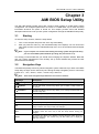
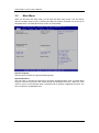
1
GOT3187W-111-PCT All-in-One 18.5” WXGA TFT Fanless Compact-Size PANEL PC User’s Manual Disclaimers This manual has been carefully checked and believed to contain accurate information. Axiomtek Co., Ltd. assumes no responsibility for any infringements of patents or any third party’s rights, and any liability arising from such use. Axiomtek does not warrant or assume any legal liability or responsibility for the accuracy, completeness or usefulness of any information in this document. Axiomtek does not make any commitment to update the information in this manual. Axiomtek reserves the right to change or revise this document and/or product at any time without notice. No part of this document may be reproduced, stored in a retrieval system, or transmitted, in any form or by any means, electronic, mechanical, photocopying, recording, or otherwise, without the prior written permission of Axiomtek Co., Ltd. CAUTION If you replace wrong batteries, it causes the danger of explosion. It is recommended by the manufacturer that you follow the manufacturer’s instructions to only replace the same or equivalent type of battery, and dispose of used ones. Copyright 2013 Axiomtek Co., Ltd. All Rights Reserved Dec 2013, Version A1 Printed in Taiwan ii Safety Precautions Before getting started, read the following important cautions. 1. Be sure to ground yourself to prevent static charge when installing the internal components. Use a grounding wrist strap and place all electronic components in any static-shielded devices. Most electronic components are sensitive to static electrical charge. 2. Disconnect the power cords from the GOT3187W-111-PCT Series before making any installation. Be sure both the system and the external devices are turned OFF. Sudden surge of power could ruin sensitive components. Make sure the GOT3187W-111-PCT Series is properly grounded. 3. Do not open the system’s top cover. If opening the cover for maintenance is a must, only a trained technician is allowed to do so. Integrated circuits on computer boards are sensitive to static electricity. To avoid damaging chips from electrostatic discharge, observe the following precautions: Before handling a board or integrated circuit, touch an unpainted portion of the system unit chassis for a few seconds. This will help to discharge any static electricity on your body. When handling boards and components, wear a wrist-grounding strap, available from most electronic component stores. Trademarks Acknowledgments Axiomtek is a trademark of Axiomtek Co., Ltd. ® Windows is a trademark of Microsoft Corporation. IBM, PC/AT, PS/2, VGA are trademarks of International Business Machines Corporation. ® ® Intel and Pentium are trademarks of Intel Corporation. AMI is trademark of American Megatrend Inc. Other brand names and trademarks are the properties and registered brands of their respective owners. iii Table of Contents Disclaimers ..................................................................................................... ii Safety Precautions ........................................................................................ iii Chapter 1 Introduction ................................................ 1 1.1 General Description ............................................................................ 1 1.2 Specifications ...................................................................................... 2 1.3 Dimensions and Outlines ................................................................... 4 1.4 I/O Outlets ............................................................................................ 5 1.5 Packing List ......................................................................................... 6 Chapter 2 Hardware and Installation .......................... 7 2.1 CF card Installation ............................................................................. 8 2.2 DRAM Installation.............................................................................. 10 2.3 HDD Installation................................................................................. 12 2.4 Wireless LAN Card Installation ........................................................ 14 2.5 Jumper and Switch Setting & COM port Connector....................... 17 2.5.1 2.5.2 2.5.3 2.5.4 2.5.5 2.5.6 2.5.7 2.5.8 2.5.9 2.5.10 Restore BIOS Optimal Defaults (JP1) ....................................................... 18 LVDS Voltage Selection (JP2) ................................................................... 18 CompactFlash™ Voltage Selection (JP5) ................................................. 18 COM1 RS-232/422/485 Mode Setting (JP6, JP9, JP10) .......................... 18 COM1 Data/Power Selection (JP7) ........................................................... 19 COM3 Data/Power Selection (JP8) ........................................................... 19 COM2 Data/Power Selection (JP11) ......................................................... 19 COM4 Data/Power Selection (JP12) ......................................................... 19 Auto Power On (JP15) .............................................................................. 20 COM port Connector ................................................................................. 20 2.6 Ethernet.............................................................................................. 20 2.7 Mountings: Panel / Wall / Desktop / VESA ...................................... 21 2.7.1 2.7.2 2.8 VESA-ARM/Wall-Mount ............................................................................ 21 Panel-mount Kit Assembly ........................................................................ 22 Power Input........................................................................................ 23 Chapter 3 AMI BIOS Setup Utility ............................. 25 3.1 Starting ............................................................................................... 25 3.2 Navigation Keys ................................................................................ 25 3.3 Main Menu.......................................................................................... 26 iv 3.4 Advanced Menu ................................................................................. 27 3.5 Chipset Menu ..................................................................................... 34 3.6 Boot Menu.......................................................................................... 39 3.7 Security Menu .................................................................................... 40 3.8 Save & Exit Menu .............................................................................. 41 Chapter 4 Drivers Installation ................................... 43 4.1 System ............................................................................................... 43 4.2 Touch Screen ..................................................................................... 43 4.3 Embedded O.S. .................................................................................. 44 v This page is intentionally left blank. vi GOT3187W-111-PCT User’s Manual Chapter 1 Introduction This chapter contains general information and detailed GOT3187W-111-PCT. Chapter 1 includes the following sections: 1.1 specifications of the General Description Specification Dimensions I/O Outlets Package List General Description The GOT3187W-111-PCT adopts a 18.5-inch WXGA TFT LCD with 300-nit brightness and an AMD G-Series APU T56N 1.65GHz dual core to provide excellent computing performance and thermal resistance. This fanless platform is especially designed for operating under heavy-duty environment including steel refinery, oil pipe, ship, machine maker operating systems and many more. Having below abilities makes GOT3187W-111-PCT surely a most robust and cost-effective solution. Wide Operating Temperature Range GOT3187W-111-PCT features a technology of wide operating temperature range which allows it to work between -10°C to +45°C. It incorporates compact ID and fanless cooling system with a low power AMD G-Series APU T56N 1.65GHz dual core, making the platform a power-efficient solution. Reliable and Stable Design The GOT3187W-111-PCT adopts a fan-less cooling system, which makes it especially suitable for vibration-heavy environments, best for the transportation, ship, and industrial machinery markets. For high capacity storage requirement, GOT3187W-111-PCT can work under 2.0G (5 ~ 500Hz, random for CompactFlash ) in operation mode with a patent of anti-vibration design. The patent improves the system reliability and sustainability. Introduction 1 GOT3187W-111-PCT User’s Manual WLAN Antenna Supported (optional) GOT3187W-111-PCT has a PCI Express Mini Card slot for optional add-ons such as wireless LAN card for 802.11 b/g connections & 3G/GPRS application, and more. It also provides an optional fixed rotational WLAN antenna for wireless network connection. More Features GOT3187W-111-PCT utilizes one 204-pin DDR3 SODIMM system memory max. up to 4GB, one SATA HDD and one CF. It provides over-current protection-fuse and a full set of I/O including RS-232, RS-232/422/485, VGA, USB 2.0, audio (line-out), and Gigabit Ethernet. Additionally, this slim unit supports panel mount, wall mount (optional), VESA mount (optional) and desktop stand (optional). 1.2 Specifications Main CPU Board CPU AMD G-Series APU T56N 1.65GHz dual core processor onboard System Chipset AMD A50M FCH System Memory One 204-pin DDR3 SO-DIMM socket Maximum memory up to 4GB BIOS America Megatrends BIOS I/O System Standard I/O 1 x RS-232/422/485, 1 x RS232 4 x USB 2.0 1 x VGA Ethernet 2 x RJ45 for Giga Ethernet Audio 1x Line-out Expansion 1 x Mini-card slot Storage 1 x 2.5” SATA TM 1 x CompactFlash slot Power connector Phoenix power connector or Screw type connector 2 Introduction GOT3187W-111-PCT User’s Manual System Specification 18.5” WXVGA(1366x768) LCD with LED backlight Projected Capacitive Touch Fanless Heat Dispensing Design IP65 front bezel Disk drive housing: One 2.5” SATA drive Net Weight 5.8 Kgs (11.02 lb) Dimension (Main Body Size) 460.8x58.5.x285mm(18.11"x2.3"x11.22") Operation Temperature -10℃ to 45℃ Relative Humidity 20% to 90% @ 40℃, Non-Condensing Power input DC version : 10~30VDC with phoenix power connector AC version : 12VDC w/adapter NOTE All specifications and images are subject to change without notice. NOTE If the operation temperature is higher than 35℃, the wide temperature HDD/CF are recommended to be used on the device. NOTE If the operation temperature is higher than 40℃, the wide temperature DRAM is recommended to be used on the device. Introduction 3 GOT3187W-111-PCT User’s Manual 1.3 Dimensions and Outlines The following diagrams show the dimensions and outlines of GOT3187W-111-PCT 4 Introduction GOT3187W-111-PCT User’s Manual 1.4 I/O Outlets Please refer to the following illustration for I/O locations of the GOT3187W-111-PCT. Introduction No Function No Function 1 POWER SWITCH (ATX) 8 USB 2.0 x 2 2 Power Input connector (Phoenix) 9 Ethernet x 2 3 Screw Conn. w/AC power adapter 10 VGA 4 Audio (Line-out) 11 CF slot 5 USB 2.0 x 2 12 Backlight Switch 6 COM 2 (RS-232) 13 Brightness adjustment 7 COM 1 (RS-232/422/485) 5 GOT3187W-111-PCT User’s Manual 1.5 Packing List When you receive the GOT3187W-111-PCT, the bundled package should contain the following items: GOT3187W-111-PCT unit x 1 Driver CD x1 Phoenix connector x 1 Panel mount kit x 12 Screws for HDD x 4 If you can not find the package or any items are missing, please contact Axiomtek distributors immediately. 6 Introduction GOT3187W-111-PCT User’s Manual Chapter 2 Hardware and Installation The GOT3187W-111-PCT provides rich I/O ports and flexible expansions for you to meet different demand, for example CF card. The chapter will show you how to install the hardware. It includes: CompactFlash™ Card DRAM Hard disk Wireless LAN Card Jumper and Switch Setting & COM port Connector Ethernet Mounting Method Power Hardware and Installation 7 GOT3187W-111-PCT User’s Manual 2.1 CF card Installation The GOT3187W-111-PCT provides one CF slot for users to install CompactFlash™ card. Please refer to the following instructions for installation: Step 1 Open the cover, unscrew 4 screws on the chassis. Step 2 Unplug the cables. 8 Hardware and Installation GOT3187W-111-PCT User’s Manual Step 3 Find the CF slot, then unscrew the CF cover. Step 4 Stick the mylar on the CF card, insert it to the CF card slot, then screw the CF cover into system. Hardware and Installation 9 GOT3187W-111-PCT User’s Manual 2.2 DRAM Installation The GOT3187W-111-PCT provides one 204-pin DDR3 SODIMM socket that supports system memory up to 4GB. Please follow steps below to install the memory modules: Step 1 Refer to section 2.1 step 1 to open the back cover. Step 2 Find the SO-DOMM connector. Step 3 Insert the DRAM to the DIMM socket, and then push it down firmly until it is clipped by the socket. 10 Hardware and Installation GOT3187W-111-PCT User’s Manual Step 4 Plug the cables. Hardware and Installation 11 GOT3187W-111-PCT User’s Manual 2.3 HDD Installation Step 1 Unscrew 8 screws on the back cover. Please refer the photo below. Step 2 Remove the back cover. 12 Hardware and Installation GOT3187W-111-PCT User’s Manual Step 3 Plug the data and power cable to HDD and screw the 4 screws into the system. Installation completes. Hardware and Installation 13 GOT3187W-111-PCT User’s Manual 2.4 Wireless LAN Card Installation The GOT3187W-111-PCT provides one Mini card slot for user to install one wireless LAN card. When installing the wireless LAN card, refer to the following instructions and illustration: Step 1 Refer to section 2.3 step 1 to open the back cover and find out mini-card slot on mainboard. Step 2 Insert the wireless LAN card to the slot. Push it down firmly until it is clipped by the slot. 14 Hardware and Installation GOT3187W-111-PCT User’s Manual Step 3 Find the Antenna cable and connect it on wireless LAN card. …. Hardware and Installation 15 GOT3187W-111-PCT User’s Manual Step 4 Remove the antenna plug from the top of back cover, and then install the antenna on the antenna connector NOTE: Please have the extented bracket when using half-size mini card. 16 Hardware and Installation GOT3187W-111-PCT User’s Manual 2.5 Jumper and Switch Setting & COM port Connector Jumper is a small component consisting of jumper clip and jumper pins. Install jumper clip on 2 jumper pins to close. And remove jumper clip from 2 jumper pins to open. Below illustration shows how to set up jumper. Properly configure jumper settings on the CAPA110/111 to meet your application purpose. Below you can find a summary table of all jumpers and onboard default settings. Note: Once the default jumper setting needs to be changed, it is suggested to be set under power-off. Jumper JP1 JP2 JP5 Description Jumper Setting Restore BIOS Optimal Defaults Default: Normal Operation LVDS Voltage Selection Default: +5V CompactFlash™ Voltage Selection Default: +3.3V 1-2 close 2-3 close 1-2 close JP6 JP9 1-2 close COM1 RS-232/422/485 Mode Setting Default: RS-232 JP10 3-5, 4-6 close 3-5, 4-6 close COM1 Data/Power Selection Default: RS-232 Data (CAPA111) CN8 Data/Power Selection Default: RS-232 Data (CAPA110) COM1 Pin 1: DCD 3-5 close COM1 Pin 9: RI 4-6 close CN8 Pin 1: DCD 3-5 close CN8 Pin 8: RI 4-6 close JP8 COM3 Data/Power Selection Default: RS-232 Data CN7 Pin 1: DCD 3-5 close CN7 Pin 8: RI 4-6 close JP11 COM2 Data/Power Selection Default: RS-232 Data CN9 Pin 1: DCD CN9 Pin 8: RI 3-5 close 4-6 close JP12 COM4 Data/Power Selection Default: RS-232 Data CN7 Pin 11: DCD 3-5 close CN7 Pin 18: RI 4-6 close JP15 Auto Power On Default: Disable JP7 Hardware and Installation 1-2 close 17 GOT3187W-111-PCT User’s Manual 2.5.1 Restore BIOS Optimal Defaults (JP1) Put jumper clip to pin 2-3 for a few seconds then move it back to pin 1-2. Doing this procedure can restore BIOS optimal defaults. Function Setting Normal (Default) Restore BIOS optimal defaults 1 2 3 1-2 close 2-3 close 2.5.2 LVDS Voltage Selection (JP2) The board supports voltage selection for flat panel displays. JP2 is used to set LVDS connector (CN1) pin 1~6 VCCM to +3.3V or +5V voltage level. Function JP2 Setting +3.3V level +5V level (Default) 1-2 close 2-3 close 2.5.3 CompactFlash™ Voltage Selection (JP5) This jumper is for CompactFlash™ voltage level selection. Use it to set CompactFlash™ connector (SCF1) pin 13 (VCC) and pin 38 (VCC) to +3.3.V or +5V. Function Setting +3.3V level (Default) +5V level 3 2 1 1-2 close 2-3 close 2.5.4 COM1 RS-232/422/485 Mode Setting (JP6, JP9, JP10) Use these jumpers to set COM1 port to operate as RS-232, RS-422 or RS-485 communication mode. When these jumpers are set to operate as RS-422 or RS485, please make sure COM1 is on data mode (see section 2.3.5) Function Setting JP6 RS-232 mode (Default) JP6 1-2 close JP9 3-5, 4-6 close JP10 3-5, 4-6 close RS-422 mode JP6 3-4 close JP9 1-3, 2-4 close JP10 1-3, 2-4 close RS-485 mode JP6 5-6 close JP9 1-3, 2-4 close JP10 1-3, 2-4 close 18 6 4 2 JP9 5 3 1 6 4 2 JP10 5 3 1 6 4 2 5 3 1 Hardware and Installation GOT3187W-111-PCT User’s Manual 2.5.5 COM1 Data/Power Selection (JP7) The COM1 port has +5V level power capability on DCD and +12V level on RI by setting this jumper. When COM1 is set to +5V or +12V level, please make sure the communication mode is RS-232 (see section 2.3.4). Function Setting Power: Set COM1 pin 1/CN8 pin 1 to +5V level Data: Set COM1 pin 1/CN8 pin 1 to DCD (Default) Power: Set COM1 pin 9/CN8 pin 8 to +12V level Data: Set COM1 pin 9/CN8 pin 8 to RI (Default) 1-3 close 3-5 close 2-4 close 4-6 close 6 4 2 5 3 1 2.5.6 COM3 Data/Power Selection (JP8) The COM3 port has +5V level power capability on DCD and +12V on RI by setting this jumper. Function Setting Power: Set CN7 pin 1 to +5V level Data: Set CN7 pin 1 to DCD (Default) Power: Set CN7 pin 8 to +12V level Data: Set CN7 pin 8 to RI (Default) 1-3 close 3-5 close 2-4 close 4-6 close 6 4 2 5 3 1 2.5.7 COM2 Data/Power Selection (JP11) The COM2 port has +5V level power capability on DCD and +12V level on RI by setting this jumper. Function Setting Power: Set CN9 pin 1 to +5V level Data: Set CN9 pin 1 to DCD (Default) Power: Set CN9 pin 8 to +12V level Data: Set CN9 pin 8 to RI (Default) 1-3 close 3-5 close 2-4 close 4-6 close 6 4 2 5 3 1 2.5.8 COM4 Data/Power Selection (JP12) The COM4 port has +5V level power capability on DCD and +12V level on RI by setting this jumper. Function Setting Power: Set CN7 pin 11 to +5V level Data: Set CN7 pin 11 to DCD (Default) Power: Set CN7 pin 18 to +12V level Data: Set CN7 pin 18 to RI (Default) Hardware and Installation 1-3 close 3-5 close 2-4 close 4-6 close 6 4 2 5 3 1 19 GOT3187W-111-PCT User’s Manual 2.5.9 Auto Power On (JP15) If JP15 is enabled for AC power input, the system will be automatically power on without pressing soft power button. If JP15 is disabled for AC power input, it is necessary to manually press soft power button to power on the system. Function Setting Disable auto power on (Default) Enable auto power on Note: 2.5.10 1-2 close 1-2 open 1 2 Each port +5V Maximum: 2A, +12V Maximum: 1A. COM port Connector The pin assignment of RS-232/RS-422/RS-485 is listed on the following table. If you need COM1 port to support RS-422 or RS-485 mode, please refer to Jumper Settings Pin RS-232 RS-422 RS-485 1 DCD TX- Data- 2 RXD TX+ Data+ 3 TXD RX+ No use 4 DTR RX- No use 5 GND GND GND 6 DSR No use No use 7 RTS No use No use 8 CTS No use No use 9 RI No use No use 2.6 Ethernet The GOT3187W-111-PCT is equipped with a high performance Plug and Play Ethernet interface, full compliant with IEEE 802.3 standard, and can be connected with a RJ-45 LAN connector. Please refer to detailed pin assignment list below: Pin Signal 1 2 3 4 5 6 7 8 20 TX+ (Data transmission positive TX- (Data transmission negative) Rx+(Data reception positive) RJ45 termination RJ45 termination Rx- (Data reception negative) RJ45 termination RJ45 termination 1 2 3 4 5 6 7 8 RJ-45 Hardware and Installation GOT3187W-111-PCT User’s Manual 2.7 Mountings: Panel / Wall / Desktop / VESA There are 4 application options for the GOT3187W-111-PCT, Panel/Wall/Desktop/VESA mountings. 2.7.1 VESA-ARM/Wall-Mount The GOT3187W-111-PCT provides VESA mount: 100x100 mm. Screw four screws to fix the kit in the back chassis. Wall mount: VESA mount: Hardware and Installation 21 GOT3187W-111-PCT User’s Manual 2.7.2 Panel-mount Kit Assembly The GOT3187W-111-PCT is designed for panel mount application. To mount the GOT3187W-111-PCT, the standard set of mounting kit (included in the system packaging) is needed. 22 Hardware and Installation GOT3187W-111-PCT User’s Manual 2.8 Power Input GOT3187W-111-PCT equips with a phoenix type power connector. It adopts 10VDC to 30VDC. Please follow the signs on power connector to connect DC power source. +: Power positive G: Safty ground -:Power negative Note: The safety ground must be connected to ensure the unit working appropriately. Hardware and Installation 23 GOT3187W-111-PCT User’s Manual This page is intentionally left blank. 24 Hardware and Installation GOT3187W-111-PCT User’s Manual Chapter 3 AMI BIOS Setup Utility The AMI UEFI BIOS provides users with a built-in setup program to modify basic system configuration. All configured parameters are stored in a 16MB flash chip to save the setup information whenever the power is turned off. This chapter provides users with detailed description about how to set up basic system configuration through the AMI BIOS setup utility. 3.1 Starting To enter the setup screens, follow the steps below: 1. 2. Turn on the computer and press the <Del> key immediately. After you press the <Del> key, the main BIOS setup menu displays. You can access the other setup screens from the main BIOS setup menu, such as the Advanced and Chipset menus. Note: If your computer can not boot after making and saving system changes with Setup, you can restore BIOS optimal defaults by setting JP1 (see section 2.3.1) . It is strongly recommended that you should avoid changing the chipset’s defaults. Both AMI and your system manufacturer have carefully set up these defaults that provide the best performance and reliability. 3.2 Navigation Keys The BIOS setup/utility uses a key-based navigation system called hot keys. Most of the BIOS setup utility hot keys can be used at any time during the setup navigation process. These keys include <F1>, <F2>, <Enter>, <ESC>, <Arrow> keys, and so on. Note: Some of the navigation keys differ from one screen to another. Hot Keys Description Left/Right The Left and Right <Arrow> keys allow you to select a setup screen. Up/Down The Up and Down <Arrow> keys allow you to select a setup screen or sub-screen. + Plus/Minus The Plus and Minus <Arrow> keys allow you to change the field value of a particular setup item. Tab The <Tab> key allows you to select setup fields. F1 The <F1> key allows you to display the General Help screen. F2 The <F2> key allows you to Load Previous Values. F3 The <F3> key allows you to Load Optimized Defaults. F4 The <F4> key allows you to save any changes you have made and exit Setup. Press the <F4> key to save your changes. Esc The <Esc> key allows you to discard any changes you have made and exit the Setup. Press the <Esc> key to exit the setup without saving your changes. Enter The <Enter> key allows you to display or change the setup option listed for a particular setup item. The <Enter> key can also allow you to display the setup sub- screens. AMI BIOS Setup Utility 25 GOT3187W-111-PCT User’s Manual 3.3 Main Menu When you first enter the setup utility, you will enter the Main setup screen. You can always return to the Main setup screen by selecting the Main tab. System Time/Date can be set up as described below. The Main BIOS setup screen is shown below. System Language Use this item to choose the system default language. System Date/Time Use this option to change the system time and date. Highlight System Time or System Date using the <Arrow> keys. Enter new values through the keyboard. Press the <Tab> key or the <Arrow> keys to move between fields. The date must be entered in MM/DD/YY format. The time is entered in HH:MM:SS format. 26 AMI BIOS Setup Utility GOT3187W-111-PCT User’s Manual 3.4 Advanced Menu Launch PXE OpROM Use this item to enable or disable the boot ROM function of the onboard LAN chip when the system boots up. The Advanced menu also allows users to set configuration of the CPU and other system devices. You can select any of the items in the left frame of the screen to go to the sub menus: ► ► ► ► ► ► ACPI Settings CPU Configuration IDE Configuration USB Configuration W83627UHG Super IO Configuration H/W Monitor For items marked with “”, please press <Enter> for more options. AMI BIOS Setup Utility 27 GOT3187W-111-PCT User’s Manual ACPI Settings You can use this screen to select options for the ACPI configuration, and change the value of the selected option. A description of the selected item appears on the right side of the screen. Enable ACPI Auto Configuration Use this item to enable or disable BIOS ACPI auto configuration. ACPI Sleep State Default the Advanced Configuration and Power Interface (ACPI) state to be S3 (Suspend to RAM). S3 Video Repost Enable or disable S3 video repost. 28 AMI BIOS Setup Utility GOT3187W-111-PCT User’s Manual CPU Configuration This screen shows the CPU Configuration, and you can change the value of the selected option. Node 0 Information View memory information related to Node 0. AMI BIOS Setup Utility 29 GOT3187W-111-PCT User’s Manual 30 IDE Configuration In the IDE Configuration menu, you can see the currently installed hardware in the SATA ports. During system boot up, the BIOS automatically detects the presence of SATA devices. AMI BIOS Setup Utility GOT3187W-111-PCT User’s Manual USB Configuration You can use this screen to select options for the USB Configuration, and change the value of the selected option. A description of the selected item appears on the right side of the screen. Legacy USB Support Use this item to enable or disable support for USB device on legacy operating system. The default setting is Enabled. Auto option disables legacy support if no USB devices are connected. Disable option will keep USB devices available only for EFI applications. USB transfer time-out The time-out value for control, bulk and interrupt transfers. Device reset time-out USB mass storage device start unit command time-out. Device power-up delay Maximum time the device will take before it properly reports itself to the host controller. “Auto” uses default value: for a root port it is 100ms, for a hub port the delay is taken from hub descriptor AMI BIOS Setup Utility 31 GOT3187W-111-PCT User’s Manual W83627UHG Super IO Configuration W83627UHG Serial Port Configuration The configuration of serial port 1~2 are set <Enabled> as default. 32 AMI BIOS Setup Utility GOT3187W-111-PCT User’s Manual H/W Monitor This screen monitors hardware health. This screen displays the temperature of system and CPU, cooling fan speed in RPM and system voltages (VCORE, +12V, +5V and +3.3V). AMI BIOS Setup Utility 33 GOT3187W-111-PCT User’s Manual 3.5 Chipset Menu The Chipset menu allows users to change the advanced chipset settings. You can select any of the items in the left frame of the screen to go to the sub menus: ► North Bridge ► North Bridge LVDS Config Select ► South Bridge For items marked with “”, please press <Enter> for more options. 34 AMI BIOS Setup Utility GOT3187W-111-PCT User’s Manual North Bridge Configuration This screen allows users to configure parameters of North Bridge chipset. AMI BIOS Setup Utility 35 GOT3187W-111-PCT User’s Manual Memory Configuration All of options are set Auto as default. Node 0 Information This item is to provide user with the information of current using DDRIII SDRAMs. 36 AMI BIOS Setup Utility GOT3187W-111-PCT User’s Manual North Bridge LVDS Config Select AMI BIOS Setup Utility 37 GOT3187W-111-PCT User’s Manual South Bridge This screen allows users to configure South Bridge chipset. For items marked with “”, please press <Enter> for more options. ► SB SATA Configuration ► SB USB Configuration ► SB HD Azalia Configuration SB SATA Configuration Use this item to select option for SATA configuration. SB USB Configuration Use this item for further setting USB port configuration. SB HD Azalia Configuration This item allows you to further control the HD audio device. 38 AMI BIOS Setup Utility GOT3187W-111-PCT User’s Manual 3.6 Boot Menu The Boot menu allows users to change boot options of the system. Setup Prompt Timeout Number of seconds to wait for setup activation key. 65535(0xFFFF) means indefinite waiting. Bootup NumLock State Use this item to select the power-on state for the NumLock. Quiet Boot Enable or disable Quiet Boot option. AMI BIOS Setup Utility 39 GOT3187W-111-PCT User’s Manual 3.7 Security Menu The Security menu allows users to change the security settings for the system. Administrator Password This item indicates whether an administrator password has been set (installed or uninstalled). User Password This item indicates whether an user password has been set (installed or uninstalled). 40 AMI BIOS Setup Utility GOT3187W-111-PCT User’s Manual 3.8 Save & Exit Menu The Save & Exit menu allows users to load your system configuration with optimal or fail-safe default values. Save Changes and Exit When you have completed the system configuration changes, select this option to leave Setup and return to Main Menu. Select Save Changes and Exit from the Save & Exit menu and press <Enter>. Select Yes to save changes and exit. Discard Changes and Exit Select this option to quit Setup without making any permanent changes to the system configuration and return to Main Menu. Select Discard Changes and Exit from the Save & Exit menu and press <Enter>. Select Yes to discard changes and exit. Save Changes and Reset When you have completed the system configuration changes, select this option to leave Setup and reboot the computer so the new system configuration parameters can take effect. Select Save Changes and Reset from the Save & Exit menu and press <Enter>. Select Yes to save changes and reset. Discard Changes and Reset Select this option to quit Setup without making any permanent changes to the system configuration and reboot the computer. Select Discard Changes and Reset from the Save & Exit menu and press <Enter>. Select Yes to discard changes and reset. Save Changes When you have completed the system configuration changes, select this option to save changes. Select Save Changes from the Save & Exit menu and press <Enter>. Select Yes to save changes. AMI BIOS Setup Utility 41 GOT3187W-111-PCT User’s Manual Discard Changes Select this option to quit Setup without making any permanent changes to the system configuration. Select Discard Changes from the Save & Exit menu and press <Enter>. Select Yes to discard changes. Restore Defaults It automatically sets all Setup options to a complete set of default settings when you select this option. Select Restore Defaults from the Save & Exit menu and press <Enter>. Save as User Defaults Select this option to save system configuration changes done so far as User Defaults. Select Save as User Defaults from the Save & Exit menu and press <Enter>. Restore User Defaults It automatically sets all Setup options to a complete set of User Defaults when you select this option. Select Restore User Defaults from the Save & Exit menu and press <Enter>. 42 AMI BIOS Setup Utility GOT3187W-111-PCT User’s Manual Chapter 4 Drivers Installation 4.1 System GOT3187W-111-PCT supports Windows 7. To facilitate the installation of system driver, please carefully read the instructions in this chapter before start installing. Step 1 Insert Driver CD and select the “\Drivers”. Step 2 Select all files and follow the installing procedure. 4.2 Touch Screen The GOT3187W-111-PCT uses the projected capacitive multi-touch. The specification is listed below. It also can drive the touch panel to get two fingers touch function that based on the Windows 7 support. Specification Touch Screen projected capacitive multi-touch Touch Screen Controller Mastouch USB Touch Screen Controller IC Communications USB interface Power Supply 5V Power Consumption 40mA Input Method Finger or Cap.Stylus Resolution 25ppi(Min.) Note: Base on WIN7 definition, ppi(Pixcel per inch) Win7 USB Driver Non-Driver Calibration Non-Calibration Drivers Installation 43 GOT3187W-111-PCT User’s Manual 4.3 Embedded O.S. The GOT3187W-111-PCT provides the WES 7E and WES 7P. The OS is supported devices which are listed below. WES 7 Here are supported onboard devices: Onboard Multi I/O SATA HDD USB CRT/LCD display 10/100/1000 base-T Ethernet Compact Flash Onboard Audio Touch Screen Note: Causing of OS limitation, only single touch function is supported under WES 7E. 44 Drivers Installation