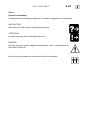
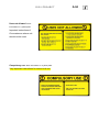
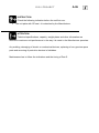
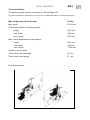
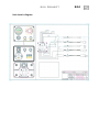
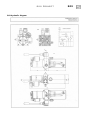
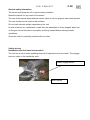
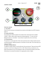
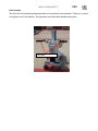
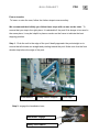
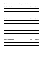
1
Owner’s Manual
- Use and maintenance for
PORTABLE POOL LIFT
DIGI PROJECT
Copyright: DIGI PROJECT
Publication: October 2005
Revised January 2011
Address of manufacturer:
DiGi Project
Via Roma, 8
46023 GONZAGA
MANTOVA
ITALY
Web:www.digiproject.biz
E-mail [email protected]
UK Distributor
Dolphin Mobility Ltd
37 ChertseyRoad
Chobham
Surrey
GU24 8PD
Web: www.dolphinlifts.co.uk
Email [email protected]
Any copy or alteration of this manual is not allowed.
Date of purchase:
1
DIGI PROJECT
The manual is divided into seven sections, each with their own symbol.
Part A (General information)
Important General information to become familiar with the BluOne portable
pool lift. Details of the unit item and Serial Number together with important
information for the operator.
..
Part B (Technical specifications )
Technical specifications–standard fitting.
Part C (Safety information and devices)
Information relating to the safety of the unit and the operator.
Part D (Operator)
Operator instructions.
Part E (Controls and devices)
Unit controls and devices.
Part F (Use)
All the information related to the unit use.
Part G (Maintenance)
All the information related to the unit regular maintenance
Part H (Service coupons)
The coupons for the service and maintenance operations.
2
DIGI PROJECT
Table of contents
1
Addresses
2
Part index
3
Topics index
PART A
GENERAL INFORMATION
A.01 General information
A.03 Unit plate
A.03 Other plates
A.05 User information
PART B
PERFORMANCES AND SPECIFICATIONS
B.02 Allowed use
B.03 Technical features
B.03 Overall dimensions
B.04 Unit diagrams
PART C
SAFETY INFORMATION AND DEVICES
C.02 General safety infomation
C.02 Safety devices
C.03 Emergency
PART D
OPERATOR
D.02 Qualification
D.02 Use and responsibility
PART E
CONTROLS AND DEVICES
E.02 Controls panel
E.02 Lift controls
PART F
USE INSTRUCTIONS
F.02 Introduction
F.03 Unit transfer
F.04 User transfer
3
DIGI PROJECT
PART G MAINTENANCE
G.02 Introduction
G.02 Check list
G.03 Disposal
PART H
SERVICE COUPONS
H.02 Service coupons
4
DIGI PROJECT
A.01
PART A
(GENERAL INFORMATION)
DIGI PROJECT
A.02
Part A
(General Information)
The purpose of the following symbols is to underline suggestions or instructions.
INSTRUCTION
Instructions for safe use and operating procedures
ATTENTION
Incorrect use may result in damage to the unit.
DANGER
Incorrect use may result in danger to the operator, user or other persons in
the vicinity of the unit.
No less than two people are needed for this kind of operation.
DIGI PROJECT
A.03
Unit plate
The unit plate is on the left side and you can find the following information:
1
Item
2
Serial Number
3
Max weight capacity
Item
Serial No.
Max weight
via Roma,8 – 46023 GONZAGA (MN) ITALY+393341200663 +393383772084
www digiproject biz
Attached plates
Instructions information –
black information on a yellow
plate.
You can find the main safety
instructions for the unit use.
DIGI PROJECT
Uses not allowed –black
information on a yellow plate.
Important instructions of
Circumstances where unit
should not be used
Compulsory use –black information on a yellow plate.
Very important instructions for correct unit use.
A.04
DIGI PROJECT
A.05
User Information
From now on the company DiGi Project is indicated as “The Manufacturer” of the unit.
This owner’s manual is in accordance with the Device Directive 89/392 and subsequent
amendments.
The use indications of this manual are those indicated by The Manufacturer.
ATTENTION:
The user must be informed of the following responsibility issues:
The Manufacturer
is responsible for the unit in the way it is made in its premises and for the use indicated in
Part B.
DIGI PROJECT
A.06
INSTRUCTION:
Check the following indication before the unit first use:
•
The unit plate with CE seal –it is attached by the Manufacturer.
ATTENTION:
Technical specifications, capacity, weight plates and other information are
referred to maximum unit performance in the way it is made in the Manufacturer premises.
Any welding, damaging of electric or mechanical devices, replacing of non-genuine spare
parts and removing of protection devices is forbidden.
Maintenance has to follow the indications and the timing of Part G.
DIGI PROJECT
A.07
Responsibility
Operator:
Responsibility for the correct and safe use of the unit, and ongoing maintenance is
deferred to the owners and operators of the equipment. The operator must be aware of the
safety information and its correspondent devices together with the use of controls,
inspection and maintenance of the equipment.
Responsibility
The operator is directly responsible for the safe use, working conditions and environment
in which the unit is operated, and to ensure that the unit is used in accordance with the
manufacturers safe working methods. The operator is also responsible for ensuring that
the equipment is inspected prior to each use, regularly inspected, cleaned and serviced in
accordance with manufacturer’s instructions and locally agreed method statements and
service regimes.
DIGI PROJECT
B.01
PART B
(PERFORMANCES AND SPECIFICATIONS )
DIGI PROJECT
B.02
Allowed use
The unit meets the requirements of the standards for breaking resistance and stress.
The unit is made in accordance with UNI CNR 10011 standards.
The unit allowed use is for portable pool lift in order to help people with disabilities in their
transfer to and from pools. The operator must use the unit by following the use indications
of the manufacturer. Any other use is not allowed.
DIGI PROJECT
B.03
Technical features
The allowed weight capacity on the seat is 120 daN (Kgs.122)
La portata consentita è costituita da un carico posto sul sedile della sedia di 120 daN (122 kgpeso.
Max. weight capacity on the seat
110 Kg
Max. travel
1150 mms.
Overall dimensions in stand-by position:
height
1250 mm
max. width
500 mm
max. length
1200 mm
Max. overall dimensions in work position:
height
1650 mm
max. width
500 mm
max. length
1700 mm
Weight in work position
Time of down-lift with weight
23 sec.
Time of up-lift with weight
17 sec.
Overall dimensions
DIGI PROJECT
Unit electric diagram
B.04
DIGI PROJECT
Unit hydraulic diagram
B.05
DIGI PROJECT
C.01
PART C
(SAFETY INFORMATION AND DEVICES)
C.02
DIGI PROJECT
General safety information
The owner must keep the unit in good working condition.
Read the manual for any need of information.
The use of the manual pump and the electric valve is only for properly instructed operator.
The unit should only be used on flat surfaces
Do not load unknown weight capacities on the unit.
In case of person on a wheelchair -make sure the wheelchair is firmly stopped, brake set
on the ground and the person is properly and firmly seated before starting transfer
operations.
Check the unit is in stand-by position before re-start.
Safety devices
Handbrake with final travel micro-switch.
The unit has a micro-switch enabling down/up lift operations from the water. The engage
device is close to the handbrake lever.
brake engage device
Micro-switch
DIGI PROJECT
C.03
Emergency Use the manual pump lever in case of hydraulic failure. (the lever is placed on
the left side of the base). The oil is pumped into the hydraulic jack when lifting the seat. In
case of electric power failure,
Does this bit mean you can emergency lower the seat by releasing the electric valve?
start the electric valve in a manual way for down-lift (see picture).
Address to service staff, once the up-lift or down-lift operations have succeeded.
manual pump lever
electric valve
DIGI PROJECT
D.01
PART D
(OPERATOR)
DIGI PROJECT
D.02
Qualifications
The staff or operator in charge of the unit must be familiar with its use and must meet the
following conditions:
Body
Good eye sight, sense of hearing and coordination, and trained to operate the equipment.
No impairment from drink or drugs. Be strong enough to manoeuvre the pool lift safely with
a person seated on board.
Behaviour
The operator must be able to assess the suitability of a person or local conditions to safely
use the equipment, for the operator, the user and other pool users. For example it may not
be safe to use if the pool is very crowded, without assistance of other staff.
Training
This manual must be carefully studied and understood by any person operating the pool
lift. The operator must become familiar with the operation of the pool lift by practicing
without persons on board until such time as they feel confident to take responsibility for the
safety of the user.
Responsibility
The owners and operators of the pool lift are directly responsible for the proper use of the
equipment, maintenance and any action related to its use.
DIGI PROJECT
E.01
PART E
(CONTROLS AND DEVICES)
DIGI PROJECT
E.02
CONTROL PANEL
5
4
2
3
1
CONTROL PANEL
Unit start controls
1) Key starter
Start the unit by turning on clockwise the key starter and the battery level LED indicators
lights on.
2) Down push-button
The lowering push-button is placed in the centre of the control panel and is marked
“DOWN”. It has a rubber shield to prevent accidental operation. To lower the chair.
Maintain pressure on the button. If you release the push-button, the unit will stop.
3) UP push-button
The up button is on the right side of the control panel and it has a rubber shield to prevent
accidental operation. Maintain pressure on the button to lift the chair. The lift will stop if you
release the button.
4) Battery charge indicator
The Battery Charge Indicator is on the left side of the control panel. There are five red LED
indicators for the level of charge from 0% to 100%. When the key is switched on, the
lights will illuminate and run a test sequence. After a few seconds the battery level will be
indicated by the constant illumination of the appropriate number of lights.
DIGI PROJECT
E.03
5) Emergency push-button
On the right top side of the panel is a large, red mushroom shaped button, marked
Emergency Stop in yellow. In the event that you need to stop the lift, depress this button.
Once the button is pushed in, you will need to turn it clockwise to release it.
6) Input for Battery Charger
Insert jack from the charger lead into the battery input terminal. The battery should be
charged for a minimum of 10 hours at least once a week.
DIGI PROJECT
F01
PART F
(USE INSTRUCTIONS)
DIGI PROJECT
F02
Introduction
Safe operating procedures.
DANGER. Use the unit in flat areas only.
ATTENTION: Check the safety devices every time you start the unit.
DIGI PROJECT
F03
Unit transfer
The Pool lift is manually operated and has to be pushed to the poolside. There is no motor
or engine to drive the wheels. The operator must hold both handles and push.
Handles
F04
DIGI PROJECT
Person transfer
To lower or raise the user, follow the further steps to ensure safety.
We recommend that initially you follow these steps with no-one on the chair. To
ensure that you stop in the right place. It is advisable if the pool lift is always to be used in
the same place, it may be helpful to place a marker on the frame to indicate the best
stopping position.
Step 1: Push the unit to the edge of the pool. Ideally approach the pool straight on to
ensure that all wheels are straight and pointing toward the pool. Make sure that the front
wheels stop before the edge of the pool.
Front wheels
Safety rubber stoppers
Step 2: engage the handbrake lever;
Handbrake engage
Safety microswitch
Pool edge
DIGI PROJECT
F05
Step 3: Check the safe and firm seat position;
Step 4: turn on the unit key starter.
Step 5: start the lift-down push-button. The microswitch only allows the operation if the
brake lever is engaged. Keep the button pushed for the required time – the lift will stop
if you release the push-button.
Step 6 The front rubber safety stoppers will lower as the seat goes down. Check
that the stoppers when lowered are above the pool deck not over the edge. When
lowered the stopper should be between 5 and 10mm above the pool deck.
Step 7 Ensure that the chair lowers into the pool and the mechanism does not clash
with the pool sides.
Once you are happy that you know the correct position for stopping the BluOne,
you can put the person on the chair, secure the seat belt and repeat Steps 1-7
and lower the person into the pool.
Step 8 a second operator is needed in the water to unfasten the security belt of the
seated person.
Recovery from the pool
Repeat Steps from 1 to 5.
Step 6: a second operator is needed in the water to check the correct seat positioning
and fasten the security belt of the seated person
Step 7: start the lift-up push-button. Keep the button pushed for the needed time up to
the travel end and the electric pump automatically stops.
Step 8: disengage the handbrake lever.
Step 9: Pull the Bluone away from the pool, and push to transfer position, where the
person can alight safely.
DIGI PROJECT
G.01
PART G
DIGI PROJECT
G.02
Introduction
Maintenance operations must be executed with the key turned off. The unit electric
devices and components must be properly protected and covered when you wash the unit.
Pressure water-jets may damage electric devices, components and wiring.
Coating finish and other anti- rust surface treatments protect all the unit components from
weather conditions. However, we suggest to check the unit coating and the surface
treatments in a regularly. If necessary, carry out ‘touch up’ repairs to surfaces.
Check list
Take care of the main maintenance operations of the unit as follows:
After 6 months of unit work
-
Check pins and joints
-
Check safety belt fixings and locks
-
Check electric connections and wiring
-
Check oil level in the oil tank
-
Check cylinder jacks for of oil leaks.
-
Check that oil is clean
-
Check that wheels and bearings are working properly, ensure tyres are not worn out
and that the wheels run straight when unit is pushed.
Every 12 months
-
Check oil-pressure cylinders
-
Check hydraulic applications and safety devices
-
Check the unit chassis
-
Inspect fluid and filter and replace if necessary
-
Check pins and joints
-
Check safety belt fixings and locks
-
Check and test electric connections and wiring
A competent member of staff must check and test all the unit safety devices, controls, and
mechanical parts if the unit is not used for a period of time longer than three months.
DIGI PROJECT
G.03
Disposal
The disposal this product must be carried out by competent agencies according to the
laws and rules of the country where the unit has been used.
PART H
(SERVICE COUPONS)
The following service coupons are for the operator and for the service use.
After 6 months of use
Date
Signature
After 12 months of use
Date
Signature
After 24 months of use
Date
Signature
After 36 months of use
Date
Signature