1
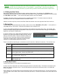
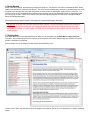
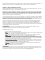
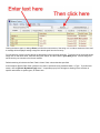
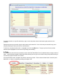
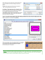
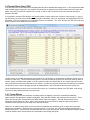
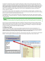
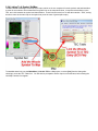
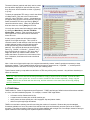
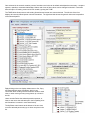
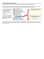
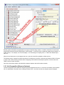
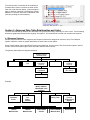
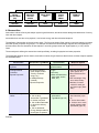
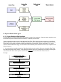
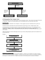
Tactical Study Series
HPS Simulations
DATAVIEW USER MANUAL
This manual is applicable to the DataView utility for all of the titles in the Tactical Study Series. Players should note that
some capabilities or systems are only included with and/or applicable to certain titles. For example, Energy Weapons
were not available in World War II and thus WWII players can ignore those data tables.
For the latest program upgrades, please visit the HPS web site:
www.hpssims.com
If you have questions, or are having problems, please email the HPS Simulations Technical Support Department:
[email protected]. If you have a saved game file that exhibits the problem, please keep it handy as we may request
that you send it to us to help recreate and identify the issue.
The complete software package and documentation are Copyright © 2003-2011 by HPS Simulations. All rights reserved.
HPS Simulations and the HPS logo are trademarks of HPS Simulations. All other trademarks and registered trademarks
are the property of their respective owners.
Introduction
Point of Attack-2 (POA), the initial release in the Tactical Study Series (TSS), was developed in partnership with the
United States Air Force Office of Scientific Research (AFOSR) and Air Force Research Laboratory (AFRL). Government
users with questions regarding the development process or objectives should contact AFOSR or AFRL directly:
http://www.wpafb.af.mil. Or, contact HPS Simulations: [email protected]. As of 2011, the point of contact at AFRL
is Dr. John Luginsland (Alexandria VA), the POC at AFRL is Mr. Dave Ross (Rome NY).
A special thanks is also extended to Dr. Bob Barker, who for more than ten years was instrumental in providing resources,
guidance, support and opportunities for the development of POA. His involvement and backing were critical in allowing
the full development of the program.
DISCLAIMER: The Energy/Advanced Weapon information contained herein was gathered by the game
author through personal research in open-literature/internet sources. The Air Force Office of Scientific
Research neither confirms nor denies any particulars of that information.
No Nonsense License Agreement
By installing the software, you are agreeing to these license terms.
You have a personal license that allows you to install the software on any computer you own, or on another computer as
long as you are an active participant in ALL games being played using the software installed on that machine. In cases
where the software is installed temporarily on a computer you do not own, it must be completely removed from the
computer at the conclusion of any active games being played.
If the software is installed on a non-commercial private network, at least one bona-fide owner of the software must be an
active participant in all games being played.
For commercial, professional (i.e., non-entertainment) or over-the-internet use all players must own their own copy of
the software or have a multiple instance license.
Players may create and freely distribute maps, scenarios, etc. that they create for the main program (as applicable to the
game). However, these modules may not be sold, or made available for sale in any manner without the written consent of
HPS Simulations.
This license is solely for non-commercial purposes. Any commercial use of this software whatsoever requires the express
written consent of HPS Simulations.
Any reports, analysis, or papers generated through any use of the program must include a reference for the full name of
the software title as well as HPS Simulations and AFOSR. For example, the official citation of a project using POA should
read: “Point of Attack by HPS Simulations, in association with the US Air Force Office of Scientific Research”.
Note: The US Government official-use version of the software may be subject to a time-limit on free usage. Please
contact HPS Simulations for more information, or if you get a “license expired” message.
Primary Credits
Design and Programming: Scott Hamilton, Jeff Lapkoff
Databases: John Kincaid, Wendy Kincaid, Nick Bell, Greg Smith, Joseph Miranda
Terrain Analysis/Development: Nick Bell
Artwork/Graphics: Nick Bell, Joe Amoral, and Jeff Lapkoff
Maps: Nick Bell, John Kincaid
Scenario Design: Greg Smith and Joseph Miranda
Playtesting: Arthur Florman, Brian Rock, Charles Belva, Don Maddox, Gary Bezant, Jim Johnson, John Kincaid, Kevin
Pelz, Michael Andress, Peter Jackson, Peter von Kleinsmid, Tim Schultz, Tyler Philpott, Dustin Pearson, Mark Ørnebjerg
Jensen.
Table of Contents
Introduction.............................................................................................................................................................................2
No Nonsense License Agreement........................................................................................................................................2
Primary Credits.......................................................................................................................................................................2
Section 1: General...............................................................................................................................................................4
1.1 Relational Data Structure...........................................................................................................................................4
1.2 The Data Tables.........................................................................................................................................................4
1.3 Editing the Data Tables..............................................................................................................................................5
1.4 Saving Data.................................................................................................................................................................5
1.5 Auto-Save Feature......................................................................................................................................................5
1.6 Auto-Backup................................................................................................................................................................6
1.7 Getting Help................................................................................................................................................................6
Section 2 General Features of Forms.................................................................................................................................7
2.1 Main Menu .................................................................................................................................................................7
2.2 Searching....................................................................................................................................................................7
2.3 Tabs............................................................................................................................................................................9
Section 3 Unique Form Operations...................................................................................................................................10
3.1 Weapons Systems Data Table – Linking Symbols..................................................................................................10
3.2 Terrain Effects Chart (TEC)......................................................................................................................................12
3.2.1 Terrain Effects....................................................................................................................................................12
3.2.2 Movement Types................................................................................................................................................13
3.2.3 Ground Conditions..............................................................................................................................................14
3.2.4 Linking To A Symbol Set/Map............................................................................................................................15
3.3 TO&E Editor..............................................................................................................................................................16
3.3.1 Units vs. Formations.............................................................................................................................................18
3.3.2 Parent Units or Formations...............................................................................................................................19
3.3.3 Unit Composition (Weapons Systems).............................................................................................................20
3.3.4 Sub-Formations.................................................................................................................................................21
3.4.5 TO&E Formation Size Considerations..............................................................................................................22
Section 4 Advanced Data Table Relationships and Links.................................................................................................23
4.1 Weapons Systems....................................................................................................................................................23
4.2 Ammunition ..............................................................................................................................................................24
4.3 Special Ammunition Types.......................................................................................................................................25
4.3.1 Cluster Munitions/Sub Munitions........................................................................................................................25
4.3.2 Ammunition That “Creates” a Unit......................................................................................................................27
4.4 Special Systems........................................................................................................................................................29
4.5 Advanced-Energy Weapons.....................................................................................................................................30
Section 1: General
The Tactical Study Series (TSS) is a set of tactical level combat simulations. It is one of the most detailed, accurate, and
overall realistic combat simulations ever produced for the commercial market, and in many ways for the professional
military as well. It was partially developed under contracts from the US Air Force Office of Scientific Research (AFOSR),
the Naval Postgraduate School, Center for Army Analysis (CAA), and the US Air Force Space Command (AFSPC).
1.1 Relational Data Structure
The data used by the simulation is broken down into a number of individual data tables, where each table contains
information limited to a specific modeling aspect of the program. This relational-database structure allows for the quick
and efficient location and editing of values of interest to a user, plus allows the values entered in one table to be used
repeatedly by other tables without having to be redefined for each. For example, an armor type defined in the Armor Data
Table can be linked to (i.e., “used by”) any number of weapons systems, as well as Improved Positions, Obstacles, and
Bridges (each of which are defined in their own tables).
This also means that when the data is changed in a table with linked values, the changes are automatically accounted for
(through the linkage) for all of the other objects that use it.
1.2 The Data Tables
Each Data Table is accessed using a button on the main form, as shown below. The buttons on the left hand side are
“Hard data tables”, in that the values are used directly by the physics-based modeling routines. The tables on the right
side, by contrast, are used principally for scenario creation and/or organization.
Quick Tip: To help insure that base values are defined and available for linking in a parent table, the Table Editing
buttons on the Main Form are arranged in order of “Top-to-Bottom”, “Left then Right”. Users are encouraged to
follow this sequence when adding new entries to prevent having to switch back and forth between multiple forms.
1.3 Editing the Data Tables
Data editing capabilities may be limited in certain versions of the program. For example, only USG/Military and
Professional users may edit most of the “left hand side” data tables. In cases where editing capabilities are not permitted,
the “Main Menu | File | Save ...” menu choices will appear grayed-out and are disabled.
In addition, data saved using one version may be incompatible with another. For instance, data saved with the
USG/Military version are incompatible with the Commercial version.
However, all users may freely view all of the Data Tables and edit the ones on the right hand side of the main form.
1.4 Saving Data
To saved changed data (if allowed per the version), either use one of the “Main Menu | File | Save...” menu options, or
click [Yes] when the “Save Now?” confirmation box appears upon closing the form.
In some cases additional table data may be saved if the current table has a dynamic link to them. For example, after
saving the Weapons System Data the Organization data may need to be saved as well since changes in the Weapons
System list can affect the TO&E entries.
If a value is entered in the “Author Name/Last Edited By” field on
the Main Form, that text string will be added to the file, and will
show up in the File List Box. Users are advised to always use
this field in order to discretely identify the person/organization
responsible for editing the file, as well as to reduce possible
confusion or conflict between different file versions.
There are six different data file types, each with the same file name but a different file extension. The extensions are:
.AIR
Default Aircraft Performance profiles.
.GUN
Gun/launcher data, Ammo data, Cluster Munition data.
.ORG
Nation/Force data, Leader data, TO&E data, Awards data.
.SPL
Mine data, Sensor data, PMD data, Engineering data, Decoy data, Laser data, IP data,
Commo System data, Jammer data, Radar data.
.TEC
Terrain Effects data, Atmospheric/Weather data, Ground Conditions data, Movement Types
data, Obstacle data, Bridge data.
.WPN
Weapons System data, Armor data, Manufacturing Country data, Sighting Profile data,
MOPP System data.
1.5 Auto-Save Feature
The Auto-Save feature is not included in the standard version.
In order to prevent unexpected loss of data the program includes an Auto-Save utility. This feature is accessed on the
Main Form, from the right hand column. Use the radio-buttons to select the auto-save time period, or to disable the
feature completely.
When enabled, all of the Data Tables will be automatically saved to file at the specified interval. The files will be named
“Autosave.NNN”, where “NNN” is the normal file extension (see above). The files will be placed in the same folder as the
parent file.
1.6 Auto-Backup
When a data file is loaded, and before any changes are made to it, it is saved to a file named “Autobackup.NNN”, where
“NNN” is the standard file extension (see above). This file is not all-encompassing, because it is updated every time a file
is loaded, but it does provides users with a first-level recourse in case of catastrophic system failure or user error. For
example, when the file “Standard.GUN” is loaded into the program, the file is automatically saved to “Autobackup.GUN”
too. As long as no other “.GUN” file is loaded, it will retain the original properties and data in the “Standard.GUN file,
before any editing takes place.
Auto-backup files are always located in the program's “\System\Autobackups” sub-folder.
IMPORTANT: Even with the Auto-save and Auto-backup features, users should always practice good file back up
and version management techniques. It is strongly suggested that users save files with new names after each
interim edit, for example “LT Hart's Update v12.WPN”, as well as backing up files to different drives, computers or
off-site locations.
1.7 Getting Help
Each table editor has its own associated Help file, which can be accessed from the Main Menu | Help | Help Text
command. This context-specific file will cover the general aspects of the Data Table and the form interface, as well as
provide a description of each field.
As an example, here is an sample from the Ammunition Data Editor Form:
In some cases, users may also refer to the main program User Manual, Part III, for more information on specific modeling
effects.
Additionally, detailed information on using the Sandbox Form is covered in the main program User Manual Appendix. The
Sandbox Form does, however, have an associated Help file of its own accessible form the Main Menu.
Section 2 General Features of Forms
Most of the Data Table Editing Forms operate in a similar fashion, with only minor variations between them. Thus, once
familiarity is gained with one form, it can be applied to the others as well.
As a general rule, the Data Table forms are “modeless”, in that a user does not need to close one form before opening
another, and thus multiple Data Tables can be open at the same time. However, because of the complex relationships
between some of the links in certain tables, users performing edits should be cautious when having more than one form
open at the same time. The forms are not always automatically “data-aware”, in that changes to one form may not be
reflected on another until that form is manually redrawn.
To edit an existing Data Table value, click on the cell containing the value. Depending on the type of value, editing will be
performed using a standard text box, up/down arrows, a drop-down, or though the use of a custom panel/form. With the
exception of a custom panel/form, which has a “Save” type button or control, to save a value after editing it simply click on
another field on the form. To cancel an edit without making any changes, hit the [Esc] key.
Changes are automatically saved in memory as they are made, but are NOT saved to disk/file until the user explicitly
selects to do so, either by a prompt when closing an editing form or the program, or though the Main Menu | File
command. This allows users to “abort” entire sessions without causing permanent, hard-to-correct errors, but it also
opens up the possibility for loss of data if the files aren't saved. Users should always remember to double check that files
are saved appropriately before exiting the program.
2.1 Main Menu
The Data Table editing forms share a general Main Menu, though not all commands will be available on all forms
depending on the data context and if other, more advanced, options are available.
The Main Menu commands are:
File: Save or load data for the current Data Table.
Reports: Print one or more reports pertaining to the Data Table (for instance a list of all entries). Output may also
be sent to a file. This option is not available for all Data Tables.
Sorting: Adjust the display order of the Data Table items. This command does not change the actual “input”
order, but only how it appears on the screen. This option is not available for all Data Tables.
Reset Col Widths: Selecting this command will reset all of the display column widths to their default sizes, and
will redraw the form. This option is especially useful if columns have become too small to view, or so large that
they crowd out other information (the size, potion, and column widths are saved for every form after each session,
and changes can sometimes build up that make general viewing inconvenient).
Move Up 1 Row/Down 1 Row/Other: Most Data Table editing forms that do not have a “Sorting” option instead
include a “Move” command. This allows users to move entries up and down within the list. In these cases, the
actual order within the table is changed, not simply the display sequence.
Preferences: This option is available on the TO&E Data Editor. It customizes specific display aspects of the
editing form. The TO&E form is covered separately, below.
Help: Display the specific help file for the Data Table.
2.2 Searching
Name search ability is provided on some of the Data Table Editor Forms, where a large number of individual entries are
expected. These editors include those for the Weapons System, Gun/Launcher, and Ammunition Data Tables. To use
the search feature, simply enter a search string in the text box, and click the [Find Next] button.
Clicking the button again (or hitting <Enter>) will find the next instance of the string, or if no further entries are found, and
a message will be displayed asking to begin the search again from the first entry.
For convenience, previous search strings are temporarily aved in the drop down box. To access one of the saved strings,
simply click on the down arrow, select the string from the list, and then click the [Find Next] button. Search strings are
not saved; they are lost at the end of each session.
Default searching is limited to the Data Table's “Name” field, unless otherwise specified.
In the Weapons System Data Table, searches may also be performed using a desired Nation, or Type. To perform this
search, click the [Search By Nation/Type] button. A separate pop-up form will appear, allowing for the selection of
specific nationalities or system types, as shown here:
To limit the selection to a specific nationality or type, use the drop-down boxes at the bottom right (as shown in the
example).
Displayed entries may be sorted using the radio buttons at the bottom left. And, the list may be searched using a text
string by following the same procedure as outlined above.
To select an entry either double-click it, or highlight it and click the [OK] button. The pop-up form will close, and the
selected system highlighted on the main form (scrolling as necessary).
2.3 Tabs
For convenience, tab controls are provided on some of the Data Table Editor Forms for tables that have a large number of
fields. These tabs group together related data fields, allowing users to get or set a desired entry quickly without having to
scroll across pages of columns of no interest.
All forms with tabs include “Complete” tab, which is selected by default. This tab shows all data fields in the table (each
data field is a column), accessed by scrolling to the right or left.
Otherwise, click on a tab to show the data fields (columns) related to that aspect of information. For example, in the
Weapons System Data Editor, clicking the “Size and Armor” Tab displays fields related to the weapons system size and
what types, thickness and angles of armor it possesses.
Note that tabs display ONLY the fields associated with the tab's information category. It is not possible, for instance, to
scroll to a non-size or armor related value when the “Size and Armor” tab is selected.
Section 3 Unique Form Operations
Most of the Data Table forms operate using a simple grid-based editor format, with no custom-linking to other Data Tables
or forms. However, there are a few exceptions, and these forms will be covered below.
3.1 Weapons Systems Data Table – Linking Symbols
With one exception, the Weapons Systems Data Table operates in a standard manner. However, the Table includes a
link to an external symbol set. This value determines what unit graphic should be displayed on the map when the
weapons system is used in a scenario, as shown here:
The “Alt Symbol” is used when the primary symbol does not exist in the set or the user's current view of the scenario (in
the Main Module).
A default symbol set is provided with the software package. However, it is possible for users to edit this set, or to create
their own using Aide De Camp (ADC), a separate utility/program published by HPS.
When the Weapons System Data Table is loaded for
viewing/edit, the system checks if a symbol set has already
been loaded. If not, it will automatically prompt the user to
load one, as shown at right.
NOTE: It is NOT necessary to load a symbol set in order
to continue viewing or editing the data. In this case, users
will simply not be able to set or view the symbol set
assignments. All the other values can still be viewed and
edited normally, however.
Symbol sets can also be loaded from the Main Menu | File | Load New Symbol Set option (if a symbol set is already
loaded, it is replaced by the new one).
After selecting to load a symbol set, select the desired set
using the standard File Selection Dialog box which will
appear.
Standard ADC symbol sets will have the file extension
“.SET”, and include both terrain and units.
For flexibility, TSS programs can utilize a second file, with
the extension “.UNT” which holds only unit symbols (no map
terrain). By breaking out the unit symbols into a separate
file, it simplifies and streamlines the unit symbol
customization process; there is no need to include or modify
the terrain/map symbols, and all of the existing map/TEC
links remain valid and unchanged.
To set the unit symbol for the weapons system after loading in a symbol set file, simply click on the Symbol cell for that
system. A selection dialog will appear, showing all of the symbols defined in the set, as well as a sample picture of each.
Select the symbol to use, and then click [Select].
Here is an example of how a unit equipped with M-1's will appear
in an actual scenario using the settings as shown above. The
size, HQ Flag and colored status indicators are added
automatically by the main program.
Quick Tip: Symbols are shown in generic “high-contrast” colors in the selection forms. Actual symbol colors are set
individually for each country in the Nation/Force Data Table. In addition, unit symbol colors can be freely adjusted
after a scenario is loaded in the Main Module using the Preferences command.
3.2 Terrain Effects Chart (TEC)
The TEC Data form is somewhat more complicated than the other standard data editing forms. In the first place the table
itself is based largely on dynamic, user-created, data structures as opposed to the fixed formats found in the other data
tables. Secondly, it requires an external link to a map, in order to “link” the terrain used on the map with the effects
defined in the table.
It is important to note that TEC editing is only required when a custom symbol set is used to create a map (i.e., using a
set other than one of the ones included with the program). Otherwise, users can, and should, use the standard TEC and
associated “.ECX” file unless there is a compelling reason to do otherwise. The “.ECX” file links the TEC to the map, and
will be covered in more detail later in this section.
The first column of the table lists the terrain types that will be “recognized” by the simulation's modeling routines (once a
scenario is under way). These defined terrain types do not need to match the symbols in a terrain set, either by name or
number, though eventually each symbol in use by a map will need to be “linked” back to one of these types to have any
effect (linking will be discussed in another section, below). So, while not required, the process becomes more convenient
and less error-prone if the terrain types are kept somewhat generic, and in line with the primary terrain symbol set.
Linear (hexside/hexline) features, such as road rivers, berms, etc., must also be defined in the TEC table, even though
they may not have defined symbols in the terrain set.
3.2.1 Terrain Effects
Terrain has many effects in the simulation, including impacts on sighting, movement, mechanical breakdowns,
electromagnetic energy/advance weapon propagation, ruble and dust creation, and protection from enemy fire. These
effects are set using the “General Data” and “Other Effects” tabs on the display. The Help file provides an exact
description of each field in the Table. How to set up desired movement effects for weapons systems and ground
conditions will be discussed in more detail in the next two sections.
However, it is worth touching briefly on how movement is handled by the simulation, since it unique from most other
wargames or simulations. Instead of fixed “movement points” or “hex costs”, the TSS uses maximum speed limits or
absolute delay times. These are then compared with the unit's “move at this speed” orders and absolute weapons system
maximum speed to arrive at how fast the unit will actually move through the terrain.
For example, a Woods terrain my have a maximum speed limit of 10 Kph for Foot movement types under Dry ground
conditions. If a foot-type unit has been ordered to move though the location at less than 10 Kph (crawling, say), or if the
weapons system itself can not travel at least 10 Kph, then the Woods location will have no effect. If, however, the unit is a
team of athletes capable of running 20 Kph, and they have been ordered to move at full speed through the woods, they
will instead be be slowed to around 10 Kph. Which makes sense, given that a person can only run so fast through the
woods – and is slowed from having to dodge trees, trip over roots, etc. (things which do not have much impact on
someone walking or crawling).
In cases where an explicit delay is more appropriate, it can be used instead of a maximum speed. For example, it may
take a man on foot 60 seconds to scale a chain link fence. In this case, the absolute delay will be added to the unit scaling
the fence (at which time their actual forward speed will be zero).
The Add/Max drop down is used to determine which effect is appropriate for the terrain type: “Add” indicates an explicit
delay, while “Max” is a maximum speed limit. The effects for a single terrain type must be defined as either of these types
– it can not be both.
Quick Tip: In general, “full hex” types of terrain (those that cover the entire location area) should be set as maximum
speed limit (Max) types, while linear features (walls, fences) are more often defined as having a discrete delay (Add).
Terrain with no movement effects can be defined by setting the type to “Add”, but the delay amount to zero seconds.
As a side note, the models automatically apply other modifications to determine actual unit speeds or delays including
speed decreases based on the incline, either up or down, loading or unloading operations, movement through smoke or
chemicals, and formation changes (moving into column to cross a bridge, for example). Traffic jams are also modeled.
For more information, please see Part III of the Main User Manual.
3.2.2 Movement Types
For simplicity, “Movement Types” are used to group weapons systems with similar movement characteristics. For
example, all types of foot soldiers and dismounted personnel walk on their own two legs, and thus all encounter terrain in
roughly the same way. Thus, rather than have each weapons system be its own movement type (and require dozens of
blocks of virtually identical data entry), instead a single “type” is created, for example, “Foot”.
Movement Types are defined/edited in the TEC editor, using the buttons at the bottom. Once a Movement Type has been
defined, it can be assigned to individual weapons systems in the Weapons System Data Table, as shown here:
Movement Types govern how a unit will interact with terrain on the map, including whether or not the unit can occupy a
certain location, and if it can, how fast it can traverse the terrain, whether it must spend time negotiating the feature, and if
it suffers any mechanical breakdown rate adjustments. The specifics are set for each Ground Condition Type, as outlined
in the next section.
3.2.3 Ground Conditions
Ground Conditions are used to adjust movement characteristics in an active scenario based on the effects of the ground
surface. For example, a person on foot will move slower over muddy or snow covered ground than they will over a
surface that is dry and clear. Or, in a more extreme example, a ski unit can only use the skis in snow or ice conditions; at
other times the skis are irrelevant and unit will simply walk at the normal dismounted foot rate.
Use the buttons at the bottom of the form to add, delete, or rename Ground Conditions.
After a Ground Condition has been defined, a new tab for it will be added to the top of the grid display. Click on this tab to
set the movement effects each defined Movement Type (which appear as columns), as shown here:
Ground Conditions are set for each scenario during the set-up phase, along with the weather and force selections. The
conditions are not static, however, and can be set to change over time as the scenario plays out. In these cases the
models will always use the current condition values; the models do not extrapolate or “average out” between different
states.
Quick Tip: Define Movement Types first, as many as possible, before adding the Ground Conditions one at a time.
After each Ground Condition is added, set the movement values for it. This reduces the risk of errors and also
promotes continuity between the effect values for different Ground Conditions.
3.2.4 Linking To A Symbol Set/Map
The Main Module modeling is based strictly on maps, which are in turn comprised of terrain symbols and hexlines/sides.
In order for the models to know what effects a symbol /line on the map should have, it requires both a definition in the
TEC, and a link between the symbol and that definition. These links are stored in a file with the extension “.ECX”, having
the same name as the main map or the symbol set (as in the case of geomorphic maps).
To establish these links, use the Main Menu | Link this TEC to a Map option, or select [Yes] from the dialog after
choosing to close the TEC Table form. You will then be prompted to load a map to use as the base, before having the
Link Map Features form appear.
The terrain features (symbols and lines) used to create
the map will be displayed on the left hand side of the
form, and each will be identified as either a “[Symbol]”
or “[Line]”.
To select an appropriate TEC entry to use for the effects
of a Map Feature, click next to the Feature's name
under the “Uses TEC Entry” column. A drop-down box
will appear listing all of the currently defined TEC types.
Select the desired TEC line to proceed (or [Esc] to
cancel the selection action). When all of the desired
links have been set, click to [Save] the ECX file.
You may also use the same link settings for other maps,
by clicking the Main Menu | Use this TEC With
Another Map. However, if the map does not use the
same symbol set or have the same line definitions,
errors will occur.
In many cases, symbol sets will contain multiple
symbols for a single terrain type. This is done for
cosmetic reasons to add variation to the final map when
multiple adjacent locations are filled with the same
terrain (and thereby prevent unattractive display
patterns). If the symbols all share the same primary
name (e.g., “Woods”, or “Woods 1”, “Woods 2”, etc.)
they can be linked as a group to a TEC entry with a
single click when any of their number is linked. To
enable this feature, check the box at the bottom of the
form. Otherwise, each feature will need to be linked
separately.
Note: In the case of geomorphic maps, the computer automatically creates “rotated” symbols as necessary to keep
alignments constant. These rotated symbols will be given generic names such as, “<SysGRS ... >”, and they will be
automatically linked to the same TEC entry as their (non-rotated) parent.
Terrain features used by a map without a valid link to a TEC entry will be purely cosmetic – they will have absolutely no
effects in scenarios.
Quick Tip: Once an .ECX link file has been generated for a map, it can be used as a “master” for all of the other
maps that use the same symbol set – there is no need to create ECX files for them separately. Simply copy the
“master” .ECX file into the folder with the other map, and then rename it to the same name as the map (keeping
the .ECX extension).
3.3 TO&E Editor
TO&E stands for “Tables of Organizations and Equipment”. TO&E's are listings of default units and formations available
to a force, and their standard equipment. For example, a certain TO&E might define:
a fire team as four riflemen with M-16's,
a squad as two fire teams plus an M-60 machine gun,
and a platoon as three squads plus a M-2 equipped Jeep and platoon leader,
and so on up through larger formations.
TO&E's are used when selecting actual forces during the creation of a scenario. Because they are the standard
formations available to a force, they make force selection both quick and historically accurate (as far as the TO&E is
accurate). They allow a scenario creator to pick an infantry battalion with a single click, for example, instead of having to
spend hundreds of clicks defining each squad and platoon individually.
Once selected in the scenario creation process, formations and units can be edited and adjusted as necessary – weapons
systems, quantities, command relationships, leaders and a host of other values can be changed as desired. Users also
have the option of creating custom units from scratch, ignoring the TO&E.
The TO&E editor allows users to edit existing formations and create new ones as desired. The left side of the form
displays all currently defined parent units and formations. The right hand side shows the general values and composition
of the selected parent.
Right-clicking on the tree display allows users to Cut, Copy,
and Paste defined parent formations, which is very
convenient when creating several formations similar to each
other, or when moving an entry many places up or down in
the list.
Users can also Delete the selected parent/component, or
insert a new one at the selected spot in the list (adding units
and formations is covered in more detail below).
The Up/Down arrow buttons at the bottom of the tree view
move the selected parent entry up or down one place in the
list.
If more than one page “worth” of TO&E entries have been
defined, the [Prev Page] and [Next Page] buttons will page
though the list. The total number of entries defined in the TO&E is shown at the bottom of the form, along with which ones
are currently shown. The number of entries shown per page can be set using the Main Menu | Preferences | TOE Lines
per display page option.
3.3.1 Units vs. Formations
In terms of the TO&E, the difference between units and formations is in their composition:
Units “equal” weapons systems (tanks, soldiers, aircraft, etc.). Units are
comprised ONLY of weapons systems, and ALL weapons systems become
part of a unit. For example, a platoon of 5 tanks is a unit, as is an infantry
platoon of 1 APC (which acts as the HQ), 12 riflemen, 3 grenadiers, and 3
machine-gun teams (as long as those troops aren't grouped into smaller
formations such as squads or fire-teams).
Formations “equal” sub-units. Formations are comprised of one or more
units or smaller formations (assigned as subordinates), plus at least one
weapons system (to act as the HQ element). In the infantry platoon example
above, the platoon would be considered a formation if it were comprised of
the APC (to act as the HQ) plus three squads (each containing 4 riflemen, 1
grenadier, and 1 machine-gun team) instead of just the weapons systems.
This is slightly different than in the Main Module (scenario execution), where each weapon system becomes a unit on its
own, and formations can include only weapons systems. However, the distinction is an important one here, in that it
dictates the procedure for creating formations in the TO&E – creation must proceed in order from small to large (the
smallest units need to be created first, so they are available in for “building” the larger formations).
Using the illustration example above, the selected US Mech Heavy Task Force is a formation. It meets the definition of
being comprised of one or more sub units or formations, in this case there are five: the Recon Platoon, the three Rifle
Companies, and the Tank Company. The formation also has three weapons systems assigned, the Command Post and
the two AFV's, which will be used to create a unit that will act as the formation's headquarters element.
Parent units and formations are designated in the left hand pane using different graphics: Units are shown as small tanks,
while formations use generic boxes with standard size indicators on top. The “size” is set using the drop-down in the
general information section, and is intended as a general reference; it does not distinguish between the unit/weapon
types, branch of service, nationality, era, etc.
Individual weapons system (unit)
Team/Individual
Squad/Air Element/Naval Element
Platoon/Air Element(+)/Naval Division
Company/Air Flight/Naval Squadron
Battalion/Air Squadron/Task Unit
Regiment/Air Task Force/Group/Naval Task Group
Brigade/Air Wing/Naval Task Fleet
Division/Air Division/Naval Task Force
Corps/Air Force/Fleet
Unknown/Unspecified
Note: Parent formations MUST still always have at least one weapons system assigned to act as the HQ element. Think
of these systems as what comprises the icon shown on the tree display.
3.3.2 Parent Units or Formations
Parent units/formations appear on the left hand panel, in a standard tree view with the appropriate size icon (as described
previously, above). They are what users will be shown, and can select from, when creating a scenario.
Clicking the [+] next to the parent icon will expand the display to show all of the subordinate weapons systems and subformations assigned to the parent. Click [-] to perform the opposite operation and condense the tree.
If a sub-formation is selected
on the tree, its information will
be displayed in the Unit
Composition and Subformation panels, as shown to
the right.
In this case the values will be
shown in gray, indicting that
they can not be selected or
edited; they are for information
purposes only.
To add a new parent unit or formation from scratch, click the [Add Unit] button at the bottom of the left hand tree view
display. A new “default” unit will be added to the bottom of the force tree (on the last page). This unit will include a single
weapon system type.
Edit the general information as appropriate for the type of element being created. If it will be a formation, the name and
level should reflect the size and nomenclature of the formation – not the sub units or weapons systems that comprise it or
its HQ element. For example, use “Tank Company”, not “Tank acting as Company HQ”, or “Three Tank Platoons plus
HQ”, etc.
After the Level has been set (or changed), the icon on the tree view will be updated to reflect the size.
The Default country of weapons systems and Active From fields are not critical. However they should be filled in if known
in order to aid in the selection processes both in assigning sub-formations and weapons systems, as well as when the
TO&E is used to create scenarios.
Once the unit has been added, edit and add the weapons systems and sub-formation normally.
3.3.3 Unit Composition (Weapons Systems)
The Unit Composition panel shows the weapons systems assigned to the unit or, in the case of formations, the formation
HQ. As stated above, all parent units, including formation HQ's, must have at least one weapons system assigned.
The “Unit Composition Panel” displays the weapons systems
currently assigned to the parent unit/formation HQ (shown with “tank”
icons in the tree view). The left column is the quantity of the system
to assign, and the right column is the system model name.
To edit the values of an existing weapons system, click on either the
quantity or name grid cell, as appropriate. When setting quantities for
formations, keep in mind that this panel is concerned ONLY with the
formation HQ – not all of the systems that may be included in subformations. They are accounted for on their own.
Weapons systems may be designated in two ways:
Specific: the exact model number is specified. When a user selects the unit/formation in the scenario creation
process, he will get the exact equipment specified (which he can then modify, if so desired).
Generic: The exact model is not specified – only the general type is (e.g., “Main Battle Tank”, “Armored
Personnel Carrier”, etc.). When a user selects the unit/formation to add to a scenario, he will be prompted to
select the exact model from the Weapons System Data Table.
To add a weapons system to the unit formation/HQ, click the [Add Specific WS] to add a specific system model, or [Add
Generic WS] to add a generic type. Generic types may also be specified as required to have Marine or Airborne
qualifications by clicking the appropriate [OK/Marine] or [OK/Airborne] button on the type selection form when saving the
pick. Note: these qualification types are set individually for equipment models in the Weapons System Data Table.
To delete a weapons system, either set its quantity to zero, or right click on it in the tree view and select “Delete” from the
pop-up menu.
Quick Tip: “Generic” should be used as the default choice when adding new weapons systems. This makes it
convenient for the scenario creator to select the model he wants to use for the situation being modeled, and also to
easily equip groups of units in the force with it. The only time “Specific” should be chosen is when the unit or
Formation HQ could NEVER be equipped with anything besides a specific model, for example a “HAWK-G Platoon”
would always have HAWK-G missiles.
3.3.4 Sub-Formations
Sub-formations are previously defined units or formations (i.e., not weapons systems) that are assigned to a higher parent
HQ. For example, to create an infantry company, three infantry platoons are assigned as sub-formations to the parent
infantry company HQ (along with other perhaps formations and units as well).
Sub-formations are not required. However, if a parent does has subformations assigned, they are displayed in the “Sub-formations
Assigned to Unit Panel”. The quantity of the sub-formation is shown
on the left, and the name on the right. Only formations or units
already defined in the TO&E can be added as sub-formations.
To edit the values of an existing weapons system, click on either the
quantity or name grid cell, as appropriate.
NOTE: When a defined formation/unit is deleted from the TO&E,
it will automatically be removed from all instances where it is
assigned as a sub-formation to a parent.
So, for instance, if the panel illustration above represents the subformations of a “US Tank Heavy Task Force”, and the “Tank
Company” is later deleted from the TO&E, the parent “US Tank
After deleting the “US Tank Company” formation
Heavy Task Force” will be left with just the “Recon Platoon” and “Rifle from the TO&E – it is automatically removed as a
Company”.
sub-formation wherever it is assigned.
To add a new sub-formation to the parent, click the [Assign an Existing Formation to this Unit] button. Then select the
formation from the pop-up list. If the selected formation has a higher level than the parent, e.g., a company is selected to
be added to a platoon, a warning notice to that effect will appear. Users may select to add the formation anyway, though
in practice this type of situation would occur extremely rarely, if ever.
3.4.5 TO&E Formation Size Considerations
There is no theoretical limit to how big (in terms of total subordinate units) a formation can be. For example, it is possible
to have a division that is ultimately comprised of 18,000 individual solders with each soldier being his own unit. However,
the realities of memory allocation and available resources would prevent such a division from ever being used in a “real”
scenario; personal computers simply don't have the memory or processor speed necessary to run such a large game.
As things currently stand, the realistic limit is about 1200 to 1500 total units per scenario, including buildings and other
battlefield objects. Therefore users should try to keep their intended “general-purpose” formations to around 150-200
units. It's OK to occasionally go over that, even to 400 or 500 units, but with the caveat that users selecting these large
formations in a scenario will be essentially limited to picking it, and only it. They will not have “room” left to also select
other combat formations or support units.
Therefore, when creating a TO&E, it is important to make the size of the units “fit” the intended scale of the map. For
example, if the map scale will be 25 meters per hex/location, then the smallest unit should be an individual vehicle or a
fire-team of 3-5 troops – something that fits comfortably within a hex of that size (~600 square meters). If units larger than
that are included in the TO&E, they will not be able to be used on the map since they can't fit in a location (in game
parlance they will “over-stack”). If a user tried to place one anyway, the computer would simply automatically reduce the
unit size to fit the map scale.
Applying the limit of 150-200 units per formation to this example, the largest formations are then going to be in the range
of companies – which are generically composed of 3 platoons of 3 squads of 2 fire teams each where each fire team is
comprised of 3 or 4 different weapons systems (each of which becomes a unit). This gives a total of 3 x 3 x 2 x 4 = 72 line
units, with a few more added in at each level for HQ and support elements, say maybe 90 total. Adding the next higher
formation, battalions (where each battalion includes three companies, plus support units), would begin to tax the total unit
limit as each battalion will likely have over 300 units.
The way around this limit is to make different TO&E's for different intended map scales. Each TO&E would then have its
“default unit” size set so that it can fit into a hex/location, which automatically creates larger formations compatible with the
total map playing area (in square Km). Examples of Map Scales and Unit/Formation sizes are:
Map Scale (meters per hex/location)
100m to 250m
†
250m to 500m
500m to 1500m
Default Unit Size
Platoon
Company
Battalion
Unit Composition
Example
M-1 Tank (Qty 5)
- or M-16 Rifle (Qty 20)
M-60 MMG (Qty 3)
M-203 G/L (Qty 3)
Dragon ATGM (Qty 3)
PRC-77 Radio (Qty 1†)
M-1 Tank (Qty 17)
- or M-16 Rifle (Qty 65)
M-60 MMG (Qty 9)
M-203 G/L (Qty 9)
Dragon ATGM (Qty 9)
PRC-77 Radio (Qty 1†)
M-1 Tank (Qty 55)
- or M-16 Rifle (Qty 210)
M-60 MMG (Qty 27)
M-203 G/L (Qty 27)
Dragon ATGM (Qty 27)
PRC-77 Radio (Qty 1†)
Maximum Formation Size
Battalion/Regiment
Regiment/Brigade
Division/Corps
Note: In this example, the radio quantity is set at one in all cases to reflect the fact that for “game purposes”, only the
formation commander has a radio; radios used within the formation are ignored. Otherwise, combat losses to the radio
would be ineffective in terms of degrading the formation's communications with its higher HQ. Users do not need to follow
this convention, however. If more radios are provided they will be used immediately to replace losses.
The exact number of units that will be created by a
formation when used in a scenario is shown at the
lower left, under the tree display. In the example at
right, for instance, selecting a US Engineer Combat
Battalion in a scenario will create 74 individual units
(including creating all sub-formations).
Section 4 Advanced Data Table Relationships and Links
The links and relationships between the data tables can get pretty confusing, especially for novice users. These following
illustrations graphically illustrate how everything “fits together”, and outlines how to create and use advanced systems.
4.1 Weapons Systems
Weapons Systems are the basic equipment and weapon items that are assigned to maneuver units. Each Weapon
System contains a number of general data fields, as well as links to other tables.
Some of these tables may be themselves linked to other data sets, as in the case of the Gun/Launcher system, which is
linked to various ammunition types, which are further linked to ammo classes.
The general relationships are diagrammed below:
Weapon System
(General Data)
Armor Data
Movement
Type
Guns/
Launchers
(up to 6)
Symbol
Ammunition
Type/Model
Special
Systems
(up to 8)
System Link
(See below)
Ammo Class
Example:
Weapon System
M1A2 “Abrams”
Main Battle Tank
(w/Dozer)
Armor Data
“Chobham”
Armor
Movement
Type
Heavy
Tracked
Gun/Launcher
7.62mm
Machine Gun
Gun/Launcher
7.62mm
Machine Gun
Gun/Launcher
120mm M256
Cannon
Symbol
Heavy Tank
Special
Systems
Engineering
System
Gun/Launcher
12.5mm M2HB
Machine Gun
System Link
Dozer Blade
Ammo Model
120mm
APFSDS M829
(DU)
Ammo Model
120mmTKAPFSDS
M1080
Ammo Model
120mm HEAT
M830
Ammo Model
120mm
STAFF
XM943
Ammo Model
TERM-KE
XM1007
Ammo Class
APFSDS
Ammo Class
APFSDS
Ammo Class
HEAT
Ammo Class
STAFF
Ammo Class
TERM
4.2 Ammunition
Ammunition is what is fired by the weapon system’s guns/launchers, and what causes damage and destruction of enemy
units and other objects.
Ammunition does not have to be physical; it can include energy and other advanced weapons.
The definition of ammunition is broken into two parts. The first is the Ammo Class, which is a general category into which
items with similar properties are grouped. For example rounds that are filled with high explosive and cause damage by
the blast effects from the detonation of that explosive, can all be grouped under the “High Explosive“ (or “HE”) Ammo
Class.
The second part is defining the ammunition model specifically, including its physical and other properties.
The relationship between ammo classes, ammunition models, the gun/launchers that fire them, and the weapons systems
are illustrated below:
Ammo Class
Ammunition Type/Model
Gun/Launcher
Weapons System
Groups w/similar
properties
Specific rounds, missiles
Specific
guns/launchers
Single vehicle/system
• Damage Method
• Guidance
• Special Properties
• Physical Properties
(size, weight, muzzle
velocity, maximum
range, etc.)
• Lethality/Damage
potential
• Special Properties
• Type
• Accuracy
• Other characteristics
(back-blast, smoke,
flash, etc.)
• General characteristics
(size, speed, etc.)
• Armor thickness and
angles.
• Gun mountings, firing
arcs, and accuracy
• Number of rounds
carried for each gun
and ammo type (basic
load)
♦ No links to any other
tables
♦ Link to Ammo Class
♦ Link to other
Ammunition Type/Model
for cluster munitions
♦ Link to Mine Data table
for land mine delivery
rounds.
♦ Link to AdvancedEnergy Weapon table for
those types of systems.
♦ Links to
Ammunition
Type/Model (up to 8)
♦ Links to
Gun/Launcher (up to
6)
♦ Link to Armor table
♦ Links to one or more
special systems table
(see below) (up to 8)
Example:
4.3 Special Ammunition Types
4.3.1 Cluster Munitions/Sub Munitions
A Cluster Munition is a type of ammunition that contains a number of sub-munitions. When the cluster projectile is over
the intended target, the sub-munitions are released (or “scattered”) over the area.
Cluster munitions are defined in the Cluster Munitions Data Table. Each cluster munition can have up to six different
types and quantities of sub-munitions. In addition, each parent cluster munition has its own dispersal pattern and area.
Sub-munitions can include ammunition models (for standard types such as HE, AP/Frag, Illumination, etc.), mines,
sensors, advanced/directed energy, and even other cluster munitions (which can have its own unique composition and
dispersal pattern).
1. If the sub-munition is another Ammunition Type/Model, define the sub-munition first in the Ammunition Data Table,
then define the parent cluster munition. If the appropriate Ammo Class is not yet defined, create it before entering the
sub-munition data. Note that the parent cluster munition does not have an Ammunition Class of its own.
Example:
Ammunition Data Table
Parent Ammunition (Define Last)
152mm ICM 3023
Cluster Munition Data Table
Parent cluster munition (Define Second)
ICM 3023 (64 Bomblets)
Ammunition Data Table
Sub-munition (Define First)
KB-2 Bomblets
Ammo Class Table
Sub-munition (Define if needed)
HE/FRAG
2. If the sub-munition is a mine, define it in the Ammo Table first, then the Mine Data table, then define the parent. If it is
delivered as part of a cluster munition, the cluster munition is defined after the Mine Entry, but before the parent munition,
as shown in the example.
Example:
Ammunition Data Table
Parent ammunition (Define Last)
155mm ADAM M718
Cluster Munition Data Table
Parent cluster munition (Define Third)
ADAM M718 (64 Mines)
Mine Data Table
Sub-Munition (Define Second)
M73 AP mine Cluster
Ammuntion Data Table
Munition (Define First)
M73 AP mine
3. If the sub-munition is a sensor, define it in the Sensor Data table first, then the parent.
Example:
Ammunition Data Table
Parent ammunition (Define Last)
Aircraft Dispersal POD/RS
Cluster Munition Data Table
Parent cluster munition (Define Second)
POD/RS (64 Sensors)
Sensor Data Table
Sub-munition (Define First)
XM10 Motion/Sound Sensor
The entire configuration, starting with the weapons system would then look like this:
Weapons System (Main)
M109A6 Paladin 155mm (SP )
Weapon #1
Gun/Launcher System
M284 Cannon 155mm
Ammo #1
Ammunition Model
M864 DP-ICM (155mm)
Sub-Munition;
Type=Cluster
Cluster Munition
M864 DP-ICM (155mm)
Munition #1
Type:Ammo
Qty=48
Munition #2
Type:Ammo
Qty=24
Ammunition Model
M42 Grenade (HE/Frag)
Ammunition Model
M46 Grenade (HE)
4.3.2 Ammunition That “Creates” a Unit
The simulation allows a unit to be created when a round of ammunition is fired. These units are of two types, Permanent
or Temporary. The type of unit created depends on the user-definable values in the Ammunition Data Table.
Permanent Units
A Permanent unit is a “standard” unit in all respects. It moves, sights, fires, and is controlled just like any other unit.
Permanent units are created when the Ammunition Data value “Special Type” is set to “Weapon System / Unit”.
A few potential uses of this scheme could be to model an aircraft taking off from a carrier, or a reconnaissance drone
launched from a bomber. In the first case, the aircraft is the “ammo”, which is “fired” from a catapult set as a
“gun/launcher” on board the carrier. In the second case, the drone is the “ammo”, launched from a pylon “gun launcher”
on the bomber.
There are no limits on how these relationships can be set up, and any existing weapons system can be selected for use
as a permanent unit.
Example:
Weapons Systems Data Table
Parent “Firing Unit”
Aircraft Carrier/ Nimitz Class
Gun/Launcher Data Table
Set as Wpn #1, Qty =1 of Aircraft Carrier
Flight Deck/Catapult Launcher
Ammunition Data Table
Special Type = “WpnsSys/Unit”
F-14D (Launch from Deck)
Weapons Systems Class Table
The new unit will consist of this system
F-14D Tomcat
Temporary or “In-Flight” Units
A temporary unit is a “standard” unit with restricted capabilities. It exists for only a limited time, and does not perform
“active” unit operations like sighting or targeting. It can also not be given orders; its actions are completely controlled by
the computer. It is also known as an “In-Flight” unit, because it will be destroyed when it reaches its destination.
Temporary units are created when the Ammunition Data value “Temp Unit When Fired” is set to “Yes”.
The rationale for creating temporary units is that the standard firing routines are limited in their effectiveness for many
types of rounds being fired. In particular, rounds that take a long time to reach their target (one or more pulses), that
follow a complicated flight path, or which can be intercepted all fall outside the capabilities of the standard model - which
assumes rounds hit their targets in the same pulse they are fired. To handle these situations, the best and easiest
solution is to convert the round into a temporary “unit”, which allows it to move and remain in play until it hits its target or is
incapacitated.
At first glance, this procedure may seem unusual and counter-intuitive. However, in reality, it makes perfect sense. While
the round is in flight (or, more appropriately, “en-route” since “rounds” traveling on the ground or in the water can be
modeled), it shares many of the characteristics of a “normal” unit. It has a size, facing, speed, elevation, and movement
path. And, it can be potentially detected and affected by enemy actions. All of which fall under the standard unit modeling
routines. So, in effect, it is a unit, even if it is out of the control of the owning player and does not perform active
operations.
Note: The selection of weapons systems for temporary units is limited to those defined as “Temporary/In Flight”
in the Weapons Systems Data Table. Normally, these will be “generic” definitions that roughly approximate the size
and characteristics of a range of similar weapons.
Example:
Weapons Systems Data Table
Parent “Firing Unit”
Destroyer/ Spruance Class
Gun/Launcher Data Table
Set as Wpn #1, Qty =1 of Destroyer
Tomahawk Launcher
Ammunition Data Table
Create Unit on Firing = “Yes”
BGM-109C Tomahawk
Weapons Systems Data Table
Must be of type “Temporary/In-Flight”
Missile (Medium Size)
Creation of the Unit
The computer creates permanent and temporary units automatically at the instant the round is “fired”. Upon creation, the
new unit is located with/at the firing unit (stacking limits are ignored) and is given an initial speed and movement path by
the computer based on current conditions. Normally, permanent units will be set to their maximum speed and will
continue on the course of their parent unit, which also becomes their “HQ”. Temporary units are always given a path that
is the most direct route to their target.
Additionally, permanent units are assigned the parent/firing unit’s values (morale, training level, etc.) and SOP orders
(targets to attack, stop to fire, etc.) However, the computer may modify some or all of the SOP values to reflect the
capabilities of the new unit as compared to the parent. On-hand ammunition quantities are calculated from the basic load
amounts (stored in the Weapons System Data able) and the force’s supply level. Once created, Permanent units revert to
the owning player’s control and become part of the normal force structure. They are also counted against stacking limits.
Temporary units, on the other hand, have no on-hand ammunition, and completely ignore status values and SOP orders.
They remain under computer control for as long as they exist, and are disregarded for stacking purposes. During each
pulse, the computer determines the elevation and other details of the unit based on the characteristics of the parent
“round”. If the round is un-powered, the unit will follow a standard ballistic path. If the round is powered but un-guided, it
will follow the best path possible within the cruise altitude and firing angle limitations. If the round is both powered and
guided, the computer will recalculate its path each pulse based on the current position of the target.
Temporary units remain in the game until they hit their target, are destroyed or incapacitated (while en-route), or reach
their maximum range. Other than direct combat results from hitting the target, temporary units have no additional effects
when they are destroyed (such as creating wrecks, starting fires, etc.).
When a temporary unit “hits” its target, the results are determined exclusively from the ammunition data table values using
the standard routines (based on warhead weight, AP radius, lethality, etc.). In the above example, these values would be
part of the entry for the “BGM109C Tomahawk” ammunition type. The weapons system, in this case “Missile (Medium)” is
used only for the en-route routines. It is ignored at impact.
The warhead can also be a cluster or other type of munition. In these cases, the normal routines will apply, just as they
would for a standard round.
Example of using a cluster munition:
Ammunition Data Table
Create Unit on Firing = “Yes”
BGM-109D Tomahawk (Cluster)
Weapons Systems Data Table
Must be of type “Temporary/In-Flight”
Missile (Medium Size)
and
Ammunition Data Table
* Same As Above *
BGM-109D Tomahawk (Cluster)
Cluster Munition Data Table
Parent cluster munition
Tomahawk Anti-Airfield (28 Bomblets)
Ammunition Data Table
Sub-munition
BLU-106/B Concrete/Pen Bomblet
4.4 Special Systems
Up to 8 total special systems are allowed per Weapons System. These systems can be of the same type, or mixed,
depending on the circumstances.
System
Description
General Contents (data
columns)
Examples
PMD *
Defeats incoming
missiles.
Type, potential targets,
covered arc, range,
sensor type
Shtora, Arena
Decoy *
Confuses guided
missiles.
Type, effectiveness
Flares, chaff
Radar *
Detects objects.
Type, range, resolution,
detectable targets
VPS-2, MPQ-53
Laser *
Designates targets for
guided munitions.
Type, range, blocking
conditions
Nd-YAG
Combat Engineering *
(3 types of actions)
Engineer operations all
normally link to the TEC
(Terrain Effects Chart) to
place the appropriate
symbols on the map.
All engineering systems
include the work-time
duration and
consumable item
requirements.
Obstacles/Terrain
Modification
Placing or removing
obstacles (abatis, log
hurdles, “tangle-foot”,
etc.). These operations
must link to the TEC to
account for the effects of
the operation.
The TEC entry includes
the obstacle/lane name,
movement costs, LOS
blocking characteristics,
concealment, and map
symbol.
Bulldozer, sappers,
demolition engineers
Mine Operations
Placing or clearing
minefields. Mine
placement operations
must link to the Mine
Data table.
The Mine Data Table
includes the mine type,
targets and lethality.
Combat engineers,
infantry.
Improved Positions
Building fortifications and
protective structures
(“foxholes”, bunkers,
pillboxes, etc.). These
operations must link to
the IP Data table.
The IP Data table
includes the IP type,
capacity, wall
composition and
protection values.
Construction engineers,
infantry w/shovels.
* Each system on this list has a separate data table.
4.5 Advanced-Energy Weapons
Advanced-Energy Weapons, including destructive lasers, electromagnetic-pulse (EMP), directed/wide area energy flux
generators and particle beam weapons, are defined as special types of ammunition. Because the physical characteristics
of these types of rounds do not directly correspond to the damage/impact they inflict, it is necessary to use a secondary
ammo type in order to model these effects. These secondary/effect definitions are defined in the Advanced/Energy
Weapons Data Table and are linked to the parent round using the “Sub-munition #1” data field (column).
As an example, take a nuclear bomb. The bomb itself has a weight, size, density, and other physical characteristics
which determine how it behaves before it detonates. However, unlike rounds that cause damage through physical
damage (impact, explosion, fracture, tunneling, etc.), these values can not be used to calculate the “non-explosive”
electromagnetic energy released by the detonation. Therefore the secondary link into the Advanced-Energy Weapons
Table provides the models with this data. (Note: the bomb's standard blast effects can be modeled through its “HE
Weight” value, even if it is in Kilotons or Megatons).
The same principle is applied to lasers – the “ammo” in this case is a “packet” of coherent light/photons that lasts for a
certain time. The “ammo” thus has no appreciable weight, size, density, etc., and all of its effects relate to the
frequency/energy of the photons themselves – characteristics that are again defined in the Advanced-Energy Weapons
Table.
To create advanced-energy weapons, follow these steps:
Create the advanced-energy weapon in the Advanced-Energy Weapon Data Table.
Create or use an existing “advanced-energy “ ammunition class, which has the appropriate type(s) of special
damage checked (Blinding DE or Destructive DE, for example).
Create an ammunition model linked to the ammunition class selected in step #2, above.
Set the ammunition model’s “Sub-Munition 1 Type” to “Adv/Energy”.
Set the ammunition model’s “Sub-Munition 1” to the appropriate advanced-energy system.
In most cases, the quantity of the advanced-energy weapon should be left at “1”.
Example:
Ammunition Data Table
Include Energy Weapon as
“Sub-Munition #1”
5 KT Tactical Nuclear Device
Ammo Class Table
“DE Damage” Flag ON
(Define Second)
Blast + Hi Energy EMP
Sub-Muntion #1
Type= “Adv/Energy
Quantity = 1
Advanced-Energy Data Table
Peak energy, dispersion, freq., etc.
(Define First)
5 Kilo-Ton Nuclear Detonation
For more information, please check the main TSS User Manual, or contact HPS Simulations at the adress/email
below.
Thanks for your support!
HPS Simulations
PO Box 3245
Santa Clara, CA 95055-3245
(408) 554-8381
www.hpssims.com


![ManualCover-3Panel10_03 [Converted]](http://vs1.manualzilla.com/store/data/005972160_1-0dfed70a109ebed97541db23da1c3e7d-150x150.png)