Transcript
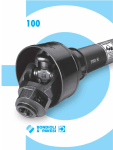
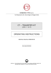
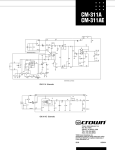
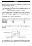
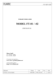
ENGLISH INDEX A. ENGLISH F. G. H. I. Becoming acquainted with K200 METER: General A.1 LC Display A.2 User Buttons A.2 How K200 METER Works Installing Daily use C.1 Dispensing C.1.1 Dispensing in Normal Mode C.1.1.1 Partial Reset C.1.1.2 Resetting the Resettable Total C.1. 2. Dispensing in Flow Rate Mode Calibration D.1 Definitions D.2 Why calibrate? D.3 Calibration procedure: D.3.1 Displays the current calibration factor and, if required, restores the factory-set factor D. 3.2 Field Calibration D.3.3 Direct modification of K FACTOR Maintenance F.1 Changing the batteries F.2 Cleaning F.3 Adjusting The Trigger Lever F.4 Cleaning The Valve Troubleshooting Technical Data Spare Parts Dimensions A. Becoming acquainted with K200 METER: General B. C. D. E. K200 METER is an electronic grease meter based on oval gears measuring system, developed for an easy and exact measurement of the grease K200 METER is studied in particular to be directly installed on lines of distribution of grease. An electronic board provided with a microprocessor allows the display management and the calibration of the device. The oval gear measuring principle adopted offers high precision and low pressure losses together with a compact lightweight design and easy installation. An electronic card with microprocessor permits control of the display and calibration of the meter. The user can choose between two different operating modes: Normal Mode: Mode with display of Partial and Total dispensed quantities Flow Rate Mode: Mode with display of Flow Rate, as well as Partial dispensed quantity. K200 METER features a non-volatile memory for storing the measuring data of the totals, even in the event of a complete power break for long periods. INSERT BATTERY The Partial register positioned in the top part of the display indicates the quantity dispensed since the RESET key was last pressed The Resettable Total register, positioned in the lower part of the display, indicates the quantity dispensed since the last ResettableTotal resetting. The Resettable Total cannot be reset until the Partial has been reset, while vice versa, the Partial can always be reset without resetting the Resettable Total. The General TOTAL register (Total) can never be reset by the user. It continues to rise for the entire operating life of K200 METER. The register of the two totals (Resettable Total and Total) share the same area and digits of the display. For this reason, the two totals will never be visible at the same time, but will always be displayed alternately. K200 METER is programmed to show one or the other of the two totals at very precise times: The General Total (Total ) is shown during K200 METER standby The Resettable Total is shown: At the end of a Partial reset for a certain time (a few seconds) During the entire dispensing stage For a few seconds after the end of dispensing. Once this short time has expired K200 METER switches to standby and lower register display switches to General Total. C.1 Dispensing The user can choose between two different operating modes: Normal Mode: Mode with display of Partial and Total dispensed quantities Flow Rate Mode: Mode with display of Flow Rate, as well as Partial dispensed quantity. A few seconds after dispensing has ended, on the lower register, the display switches from Resettable Total to General Total: the word RESETTABLE above the word TOTAL disappears, and the Resettable Total is replaced by the General Total. MEASUREMENT CHAMBER LCD Display 7 8 2 6 7 8 A.2 D.2 - for the RESET key, resetting the partial register and Resettable Total - for the CAL key, entering instrument calibration mode and, for some versions, “Flow Rate” activation mode Partial Reset The Partial Register can be reset by pressing the RESET key when K200 METER is in Standby, meaning when the display screen shows the word “TOTAL”. • • At the end of the process, a display page is first of all shown with the reset Partial and the Resettable Total on-the-spot calibration may be required to suit the real conditions in which K200 METER is required to operate. 10 How K200 METER Works B. Installing K200 METER can be installed directly on the tube for grease delivery. The body is provided with two female threads 1/8” (BSP or NPT according to the versions) on which to install the tube for grease. ATTENTION Always make sure that the thread on the hose and on all attachments applied are compatible with the thread on the chosen K200 METER model. To avoid damaging the grease handle, always fasten every component tightly using the appropriate tools. Make sure the grease is free from impurities; foreign matter in the grease can obstruct the measuring gears. For the grease handle to function properly, air should be removed from the grease supply line, ensuring a smooth and regular grease flow. D.3.3 Direct modification of K FACTOR The calibration phases can be entered (by keeping the CAL key pressed for a long time) to : Display the currently used calibration factor Return to factory calibration (Factory K Factor) after a previous calibration by the user Edit current calibration factor. This procedure is especially useful to correct a “mean error” obtainable on the basis of several performed dispensing operations. If normal K200 METER operation shows a mean percentage error, this can be corrected by applying to the currently used calibration factor a correction of the same percentage. In this case, the percentage correction of the USER K FACTOR must be calculated by the operator in the following way: In calibration mode, the partial and total dispensed quantities indicated on the display screen take on different meanings according to the calibration procedure phase. In calibration mode, K200 METER cannot be used for normal dispensing operations. In “Calibration” mode, the totals are not increased. ATTENTION K200 METER features a non-volatile memory that keeps the data concerning calibration and total dispensed quantity stored for an indefinite time, even in the case of a long power break; after changing the batteries, calibration need not be repeated. D.3.1 New CAL Factor = Old CAL Factor * Example: Error percentage found E% CURRENT calibration factor New USER K FACTOR Daily use ) - 0.9 % 1,000 1,000 * [(100 – ( - 0,9))/100]= 1,000 * [(100 + 0,9)/100] = 1.009 If K200 METER indicates less than the real dispensed value (negative error) the new calibration factor must be higher than the old one as shown in the example. The opposite applies if K200 METER shows more than the real dispensed value (positive error). OPERATION 1 Display Configuration Problem Possible Cause Remedial Action LCD: no indications Battery discharged Check battery and battery contact Not enough measurement precision Meter loses calibration check the calibration factor Pump sucks in grease and air Put the pump in a proper position The pump sucks grease and air Reposition properly the pump Reduced or zero flow rate Gears blocked Clean the measurement chamber K200 METER does not count, but the flow rate is correct Incorrect installation of gears after cleaning Repeat the reassembly procedure Possible electronic board problems Contact your dealer Indication Err xx yy, after Problem of memorization of dates RESET+CAL pressing Deliver/meter a small quantity, wait for 2 seconds, press RESET, press RESET+CAL. Should the same error be displayed, contact your supplier. K200 METER ITALIANO MANUALE DI USO, MANUTENZIONE E CALIBRAZIONE ENGLISH USE, MAINTENANCE AND CALIBRATION MANUAL NONE K200 METER in Stand-by. 2 LONG CAL KEY KEYING K200 METER enters calibration mode, and the display shows “C” and the current calibration factor instead of the partial . The words “Fact” and “User” indicate which of the two factors (factory or user) is currently being used. 3 LONG RESET KEY KEYING K200 METER displays “FIELD” and the partial at zero: K200 METER is ready to perform field calibration by dispensing – see previous paragraph. 4 LONG RESET KEY KEYING We now go on to Direct change of the calibration factor: the word “Direct” appears together with the currently used calibration factor. The lower left corner of the display will show an arrow (up or down) that says how the factor will change (increase or decrease) when the following steps 5 or 6 are performed. 5 SHORT RESET KEY KEYING Changes the direction of the arrow. The operation can be repeated to alternate the direction of the arrow. 6 SHORT/LONG CAL KEY KEYING The indicated value changes in the direction indicated by the arrow one unit for every short CAL key keying continually if the CAL key is kept pressed. The speed increase rises by keeping the key pressed. If the desired value is exceeded, repeat the operations from point (5). 7 LONG RESET KEY KEYING K200 METER is informed that the calibration procedure is finished. Before performing this operation, make sure the indicated value is that required. 8 NO OPERATION At the end of the calculation, the new USER K FACTOR is shown for a few seconds, after which the restart cycle is repeated to finally achieve standby condition. The word “user” indicates a calibration factor set by the user is being used. The flowchart below shows the logical passages from screen to screen After the restart cycle, K200 METER uses the calibration factor that has just been confirmed Important: When the Factory Factor is confirmed, the old User factor is deleted from the memory Resetting the Resettable Total Field Calibration This procedure calls for the grease to be dispensed into a graduated sample container in real operating conditions (flow rate, viscosity, etc.) requiring maximum precision. ATTENTION For correct K200 METER calibration, it is most important to: • Provide yourself with a precision balance with resolution 0.01 gr/ml/oz • completely eliminate air from the system before calibrating; • use a precise Sample Container with a capacity of not less than xxx kg, featuring an accurate graduated indicator. • ensure calibration dispensing is done at a constant flow rate equivalent to that of normal use, until the container is full; • Do not dispensing more than 999.9 gr/ml/oz in order to keep the resolution of 0.1 gr/ml/oz. • Carefully follow the procedure indicated below. 5. The display screen again shows all the segments of the display followed by all the switched-off segments and finally shows the display page where the reset Resettable Total is shown. OPERATION 1 Dispensing with Flow Rate Mode display It is possible to dispense fluids, displaying at the same time: the dispensed partial the Flow Rate in [Partial Unit / minute] as shown on the following display page: Procedure for entering this mode: wait for the meter to go to Standby, meaning the display screen shows Total only quickly press the CAL key. Start dispensing The flow rate is updated every 0.7 seconds. Consequently, the display could be relatively unstable at lower flow rates. The higher the flow rate, the more stable the displayed value. The flow rate is measured with reference to the unit of measurement of the Partial. In the example shown, the flow rate is expressed in ml/min. To return to “Normal” mode, press the CAL key again. If one of the two keys RESET or CAL is accidentally pressed during the count, this will have no effect. Important: Even though in this mode they are not displayed, both the Reset Total and the General Total (Total) increase. Their value can be checked after dispensing has terminated, returning to “Normal” mode, by quickly pressing CAL. Display IMPORTANT: From now on, the indicated factor will become the calibration factor used by K200 METER and will continue to remain such even after a battery change NONE K200 METER in Stand-by 9 2 LONG CAL KEY KEYING K200 METER enters calibration mode, and the display shows <<C>> and the current calibration factor instead of the partial . The words “Fact” and “USER” indicate which of the two factors (factory or user) is currently in use. Important: This factor is that which the instrument also uses for field calibration measurement operations 3 LONG RESET KEY KEYING K200 METER displays “FIELD” and the partial at zero: ready for field calibration. 4 DISPENSING INTO SAMPLE CONTAINER Without pressing any key, start dispensing into the sample container. Partial Reset Dispensing can be interrupted and started again at will. Continue dispensing until the level of the grease in the sample container has reached the graduated area. There is no need to reach a preset quantity. To reset the Partial Register, finish dispensing and wait for the meter to show a Flow Rate of 0.0 as indicated in the illustration then quickly press RESET K200 METER is supplied ready to use. No commissioning operations are required even after long storage periods. ATTENTION • K200 METER is designed for professional use and should be operated only by authorised adult personnel. • Do not use K200 METER in conditions exceeding the limits described in the “SPECIFICATIONS” section or with fluids other than lubricating grease. • Do not modify or tamper with K200 METER • Check K200 METER periodically to make sure it is in good conditions • K200 METER is a high-precision grease meter. Never aim the nozzle toward any part of your body or toward anyone else. • Use all personal protection equipment prescribed by law • Discharge the pressure in the supply line before performing maintenance. ( 100 - E% 100 Displays the current calibration factor and, if required, restores the factory-set factor The word “Fact” abbreviation for “factory” shows that the factory calibration factor is being used 4. With the display showing the ResettableTotal, press Reset for at least 1 second C.2.1 F. Troubleshooting Two procedures are available for changing the Calibration Factor: 1. FIELD CALIBRATION, performed by means of a dispensing operation 2. DIRECT CALIBRATION, performed by directly changing the calibration factor 3. K200 METER starts to reset the Partial. C.2. NO OPERATION K200 METER stores the new calibration factor and is ready for dispensing, applying the newly defined USER K FACTOR. K200 METER permits making quick and precise electronic calibration by changing the Calibration Factor (K FACTOR). and, after a few moments, the Resettable Total is replaced by the NON resettable Total (Total). Proceed as follows: 1. Wait for the display to show normal standby display page (with Total only displayed), K200 METER’s metering system is based on a measuring chamber that contains two oval gears that, when rotating, generate electric impulses which are detected and processed by a microprocessor. The gears are made to turn by the grease flowing through the chamber. The volume of grease that flows through is calculated by the number of gear rotations, given that each rotation corresponds to an identical amount of grease. The magnetic coupling, between the magnets installed on the gears and a magnetic switch outside the measurement chamber, ensures measurement chamber sealing and ensures transmission of the pulses generated by gear rotation to the electronic board microprocessor. By applying an appropriate calibration factor, the microprocessor transforms the impulses into the amount of grease (in weight) that has been dispensed, and displays the result on the LC display. All K200 METER models are factory set with a calibration factor called FACTORY K FACTOR equal to 1,000. For best K200 METER performance - adapting this to the intrinsic characteristics of the grease to be measured - the instrument can be “calibrated”. Calibration can be restored to factory settings at any time (see “Calibrating”). ATTENTION Only one gear is equipped with magnets. The gear with the magnets must be installed as shown in the figure above, with the magnets towards K200 METER’s body. The other gear (without magnets) must be installed with its major axis at right angles to the first gear. Make sure the gears are turning freely before closing the cover. TIGHTENING TORQUE: 10 Nm D3. Calibration procedure: D. 3.2 CAL BUTTON To clean the chamber, proceed as follows (with reference to the spare parts list positions): • Unscrew the four screws that hold the cover (pos.1) and remove the respective washers ; • Remove the cover and the cover gasket (pos.1-3); • Take out the oval gears (pos. 2); • Clean where necessary. For this operation, use a brush or pointed object such as a small screwdriver. Be careful not to damage the body or the gears. • To reassemble the instrument follow the same steps in reverse order, and refer to the figure above to put the gears back correctly. IMPORTANT: From now on, the indicated factor will become the calibration factor used by K200 METER and will continue to remain such even after a battery change using grease with viscosity in the extremes of the acceptable range in extreme flow rate conditions (close to minimum or maximum acceptable values) The Resettable Total resetting operation can only be performed after resetting the Partial register. The Resettable Total can in fact be reset by pressing the RESET key at length while the display screen shows RESETTABLE TOTAL as on the following display page: RESET BUTTON NO OPERATION At the end of the calculation, the new USER K FACTOR is shown for a few seconds, after which the restart cycle is repeated to finally achieve standby condition. K200 METER is supplied with a factory calibration that ensures precise measuring in most operating conditions. Nevertheless, when operating close to extreme conditions, such as for instance: 2. Press the RESET key quickly C. Why calibrate? C.1.1.1 C.1.1.2 User Buttons ATTENTION Before opening the measuring chamber, make sure the supply line is not pressurized. - User K Factor: Customized calibration factor, meaning modified by calibration. a) If no calibration has ever been performed, or the factory setting has been restored after previous calibrations, the following display page will appear: and then all the digits that are not lit up. Partial register (4 figures with moving comma: 0.0 ÷ 9999 ), indicating quantity dispensed from when the RESET button was last pressed; Indication of Flow Rate mode Indication of calibration mode; Totals register (6 figures with moving comma 0.0÷999999), that can indicate two types of Total: 4.1 General Total that cannot be reset (TOTAL) 4.2 Resettable total Indication of unit of measurement of Totals: kg = kilograms L=Litres lb= pounds Indication of type of total, (TOTAL / RESETTABLE TOTAL); Indication of battery charge; Indication of unit of measurement of Partial: g = grams ml = millilitres oz = ounces It is rarely necessary to clean the measuring chamber; cleaning is quick and easy and you don’t need to disconnect K200 METER from the supply line. Real value 9 Even after any changes have been made by the user, the factory K factor can be restored by means of a simple procedure. Two cases can occur: After pressing the RESET key, during reset, the display screen first of all shows all the lit-up digits K200 METER features two buttons (RESET and CAL). The main functions performed are: A.3 Indicated value M0119ITUK rev1 E.2. Cleaning SHORT/LONG CAL KEY KEYING The indicated value changes in the direction indicated by the arrow - one unit for every short CAL key keying - continually if the CAL key is kept pressed. The speed increase rises by keeping the key pressed. If the desired value is exceeded, repeat the operations from point (6). LONG RESET KEY KEYING K200 METER is informed that the calibration procedure is finished. Before doing this, make sure the DISPLAYED factor is the ACTUAL factor (see previous point 7). K200 METER calculates the new USER K FACTOR ; this calculation could require a few seconds, depending on the correction to be made. If, on the other hand, calibrations have been made by the user, the display page will appear showing the currently used calibration factor ( in our example 0,998) . 4 ENGLISH 8 b) 6 5 3 5 Calibration factor or “K Factor” : this is the multiplication factor applied by the system to the electrical pulses received, to transform these into measured grease units This situation is called STANDBY and remains stable until the user operates K200 METER again. 1 2. 3 4 Definitions 7 By pressing the CAL key while the appliance is in Standby, the display page appears showing the current calibration factor used. The “LCD” of K200 METER features two numerical registers and various indications displayed to the user only when the applicable function so requires. Key: 1 D.1 Should one of the two keys RESET or CAL be accidentally pressed during counting, this will have no effect. RESET BUTTON A.1 Calibration This calibration factor ensures utmost precision in the following operating conditions: grease NLGI grade 2/3 Temperature: 20°C Flow rate: 0.1-2.5 Kg/min 0.1-2.8 L/min 0.2-5.5 lb/min This is default mode during which, while the count is made, the Partial and Resettable Total are displayed at the same time. CAL BUTTON D. ENGLISH - Factory K Factor: Factory-set default factor. It is equal to 1,000. C.1.1 Dispensing in Normal Mode LCD DISPLAY The measurement electronics and the LCD display are fitted in the top part of the meter, isolated from the fluid-bath measurement chamber and sealed from the outside by means of a cover The only operations that need to be done for daily use are Partial and/or Resettable Total register resetting. Below are the two typical normal operation displays. One display page shows the Partial and Resettable Total registers. The other shows the partial and general total. Switchover from Resettable Total to general Total display is automatic and tied to phases and times that are factory set and cannot be changed by the user. ENGLISH Unlike Normal mode, in this case during reset, you do not pass through the stages where the display segments are first lit up and then switched off, but rather the reset partial register is immediately displayed. Indicated value 5 6 Real value SHORT RESET KEY KEYING K200 METER is informed that the calibration dispensing operation is finished. Make sure dispensing is correctly finished before performing this operation. To calibrate K200 METER, the value indicated by the partial totaliser (example 9.800) must be forced to the real value marked on the graduated sample container. To do this follow the instructions in sections 6 and 7. SHORT RESET KEY KEYING Lets you choose the direction of the arrow in the lower left corner of the display. The up arrow increases the factor shown, and the down arrow reduces it . The operation can be repeated to alternate the direction of the arrow. NO OPERATION K200 METER stores the new calibration factor and is ready for dispensing, applying the newly edited USER K FACTOR. DICHIARAZIONE DI CONFORMITA’ In accordo con lla direttiva: 89/336/CEE (compatibilità elettromagnetica) e successive modifiche PIUSI S.p.A. - 46029 Suzzara (Mantova) Italy dichiara che il seguente modello di contalitri E. K200 METER Maintenance K200 METER has been designed to require a minimum amount of maintenance. The only maintenance jobs required are: • Battery change – necessary when the batteries have run down; • Cleaning the measurement chamber. This may be necessary due to the particular nature of the grease. ATTENTION Maintenance should be performed only by authorised personnel who have read and understood this manual. In order to guarantee the product’s functionality, always choose original spare parts when replacing damaged components. a cui la presente dichiarazione si riferisce, rispetta la applicabili normative indicate nel seguito: Normative europee: EN 61000-6-1; EN 61000-6-3; EN 55014-1-2000; EN55014-2-97 Suzzara li 01/01/2004 il Presidente. Otto Varini E.1. Changing the batteries K200 METER is complete with 2 x 1.5 V. alkaline batteries SIZE N MN9100 LR1 . K200 METER features two low-battery alarm levels: 1) When the battery charge falls below the first level on the LCD, the fixed battery symbol appears. In this condition, K200 METER continues to operate correctly, but the fixed icon warns the user that it is time to change the batteries. 2) If K200 METER operation continues without changing the batteries, the second battery alarm level will be reached which will prevent operation. In this condition the battery icon starts to flash and is the only one to remain visible on the LCD. ATTENTION Do not discard the old batteries into the environment. Refer to local disposal regulations. When replacing the batteries, refer to the figure opposite and to the spare parts list, and proceed as follows: • Press RESET to update all the totals • Unscrew the battery cap (pos.6) • Remove the old batteries • Place the new batteries in the same position as the old ones, making sure the positive pole is positioned as indicated alongside. • Re-tighten the battery cap, making sure the seal and tapered spring are correctly positioned. • K200 METER will switch on automatically and normal operation can be resumed. After changing the batteries and, subsequently, every time there is a power break, K200 METER will start again and use the same calibration factor used when the break occurred. K200 METER does not therefore need calibrating again. DECLARATION OF CONFORMITY In conformance with the directives 89/336/CEE (compatibilità elettromagnetica) e successive modifiche PIUSI S.p.A. - 46029 Suzzara (Mantova) Italy declares that the followinf X-Meter K200 METER To witch this declaration refers, conforms to the following applicable regulations: European Regulations: EN 61000-6-1; EN 61000-6-3; EN 55014-1-2000; EN55014-2-97 Suzzara li 01/01/2004 the President Otto Varini Bulletin M0119ITUK rev.1