1
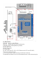
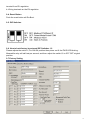
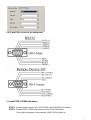
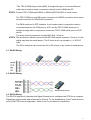
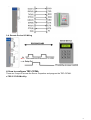
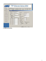
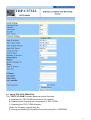
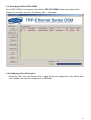
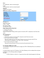
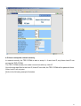
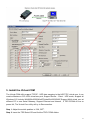
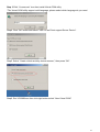
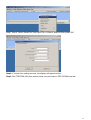
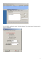
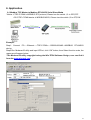
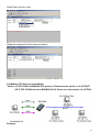
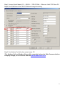
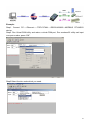
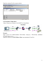
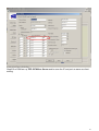
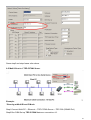
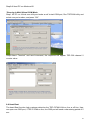
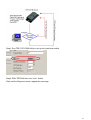
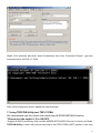
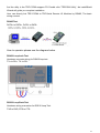
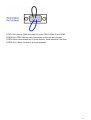
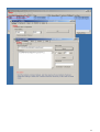
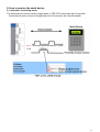
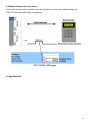
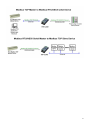
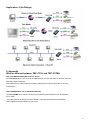
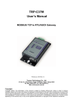
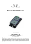
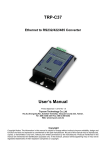
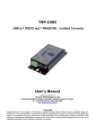
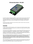
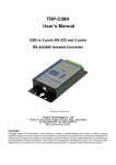
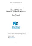
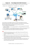
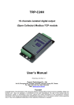
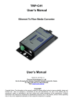
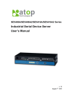
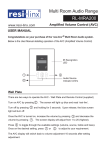
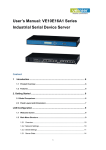
TRP-C37MA User’s Manual MODBUS TCP to RTU/ASCII Gateway User’s Manual Printed DEC 17 2015 Rev 1.2 Trycom Technology Co.,Ltd No.35, Zhongxing Rd., Guishan Township, Taoyuan County 333, Taiwan. Tel : 886-3-350-3351 Fax: 886-3-350-3352 Web: www.trycom.com.tw Copyright Copyright Notice: The information in this manual is subject to change without notice to improve reliability, design and function and does not represent a commitment on the part manufacturer. No part of this manual may be reproduced, copied, or transmitted in any form, without prior written permission by the manufacturer. Products mentioned in this manual are mentioned for identification purposes only. In this manual, product names appearing may or may not be registered trademarks of their respective companies or copyright. 1. Introduction The TRP-C37MA which is able to analyzes the protocols between Modbus TCP and Modbus RTU / ASCII. It able to assign the UID of Modbus TCP slave from Modbus Serial Master. The TRP-C37MA which is suitable industrial environment Ethernet serial server, wide range power input and serial communicate protection, It Built-in surge, over current, over voltage ensure RS422 / 485 serial communication quality; if user lost password that can fast back to default by external switch. The TRP-C37MA can as serial server that support 3 operates mode, "Direct IP Mode", "Virtual COM Mode", and "Paired Mode", these modes are supported Modbus RTU / ASCII protocols. The TRP-C37MA offers maximum connection 16 host clients to link the one serial server, it is easy to operate in Modscan32 and Modbus Poll many application uses Virtual-COM mode and Pair Mode. In network security, the TRP-C37MA is able to set up 8 sets host IP, only these host IP can access the TRP-C37MA. The TRP-C37MA provides a watchdog timer function, The Watchdog timer allows the system to automatically recover from a system crash. When the TRP-C37MA MCU stop working correctly, the watchdog timer waits for a preset period of time, and performs a hardware reset . When The TRP-C37MA working at unstable voltage industrial environment, the power detection circuit can prevent the power fail cause of the boot fail then auto re-boot. The TRP-C37MA will be auto detects function which will be auto connect when the LAN disconnect then re-connect or power off then power on. In addition to Modbus TCP to RTU/ASCII function, The TRP-C37MA is able to remote monitoring serial device. There are 2 models to choose from: Automatic monitoring mode: The Serial device must be sends a single pulse to TRP-C37MA continually per 30 seconds. If serial device do not send a single pulse over 30 seconds ,the TRP-C37MA will be actives the relay. Manual mode: If the serial device need to restart, user can feel free to set the relay enable through the TRP-C37MA web configuration. 1-1. Features Automatic remote monitoring serial device. Automatic restart the serial device. Direct active the relay by web page. Read the counter value and DI status from web based utility. Adjustable relay latch time from web based utility. Wide input range DC power supply. Power Input detection circuit. External watchdog function prevents system or power fail. Support Auto-MDIX twisted pair crossover detection and Auto-Correction. Maximum Connection 16 Client PC at Server Mode. Compatible with Modscan32, Modbus Poll, CAS Modbus Scanner and SCADA .. Application. 2 Maximum 8 sets host IP that limits network access. Surge protection and over current and over voltage on RS-422/485 data lines. Support baud rate from1200~921600Kbps. Auto switching RS-232/422/485 signal interface. Virtual COM drivers for WIN98/2000/XP/Vista/2003/7/8/8.1 and WIN10. Virtual Com Support Server, Client, UDP mode. Virtual Com Support Modscan32 or Modbus Poll utility. Fully compatible with Ethernet and TCP/IP protocol. Supports 10/100 Mbps Ethernet. Power/Link/UART RX/UART TX mode LED indicator. Heart Beat function ensures a reliable communicating connection. Auto reconnection when power or Ethernet fail. Back to factory configuration by external switch. Update the firmware from LAN. Dual power input select from screw terminal or DC-Jack. 1-2 . Specification Power Input Voltage: DC +10V to +30V. LAN: Auto-MDIX, 10/100 Mbps Auto-detecting. RS-232: TX, RX, RTS, CTS, DTR, DSR, DCD, GND. RS485 signal: differential 2 half-duplex wires (DATA+, DATA-). RS422 signal: differential 4 full-duplex wires.(TX+,RX+,TX-,RX-) Baud Rate: 1200,2400,4800,9600,19200,38400,57600,115200,921600 K bps. Parity: none, even, odd. Data Bits: 5, 6, 7 or 8. Stop Bits: 1, 1.5 or 2. Protocol: TCP, IP, ARP, DHCP, Telnet, HTTP, UDP, ICMP. Modbus TCP Type: TCP Master to Serial Slave, TCP Slave to Serial Master. TCP Slave to Serial Master Mode: Maximum 8 TCP Port. UID Range:00~FF. External switch: OFF OFF : Directly IP mode, RTU protocol. ON OFF: Virtual-Com and Paired mode . OFF ON: Directly IP mode, ASCII protocol ON ON: Back to Factory. Virtual-Com mode support RS232 TXD,RXD,GND. RS422 TX+,TX-,RX+,RX-. RS485 D+,D-. Heartbeat function: TCP 5300 port send a strings per 5 seconds. Maximum TCP connections at the same time: 16. Digital I / O connector: D-type 9PIN female. Digital input an effective voltage: DC +/- 4 ~ 30V. Digital Input count: 0~65535. Relay setting start to closing time: 1 ~ 255 (100ms / unit). Relay specifications: two independent NC, COM, NO. 3 Relay contact capacity: AC 125V / 0.5A, DC 30V / 2A, DC110V / 0.3A. Power supply: Screw terminal, or DC jack. Serial interface: +/-15 KV ESD. RS422/485 interface: Surge, over current, over voltage protection. RS422/485 interface: Industrial plug-in screw terminal. Plug-in screw terminal wiring: Accepts AWG #12 ~30 wires. Power consumption: 12V/140mA. Operating Temperature: -10 to 65 °C. Humidity: 0~90% Non-Condensing. Dimensions: 151(L)*75(W)*26(H) mm. Weight: 395g with packing. 2. Hardware Description The following information is provided to give the user an understanding of how to connect the TRP-C37MA to the LAN and serial device. A review of the switch settings and the functionality of the LED’s are also provided. 2-1. Panel layout 4 2-2. LED indicator PWR LED: System is ready.(Blinking) LINK LED: Ethernet cable connection and data active. TX/RX LED: UART Transiting/Receiving Indicator. DI LED: Digital Input. DO LED: Relay Active. 2-3. Power Input DC Jack: Power Input DC +10V to +30V. (Please use the 5.5*2.1mm DC JACK). There are two types power input. a. Use the plug of power adaptor than plug in the DC jack on the side. This approach also allows the user to provide additional power to other devices using the 5 terminal from EU regulation. b .Wiring terminals on the EU regulation 2-4. Reset Button Push the reset button will Re-Boot. 2-5. DIP Switches 2-6. How to back factory by external DIP Switches 1,2 Please adjusts the switch 1,2 to ON ON position then power on till the PWR LED blinking. Meanwhile relay will self-test per second, and then adjust the switch1,2 to OFF OFF original position. 2-7.Factory Setting 6 2-8. D-sub 9 Pin connector pin assignment 3. Install TRP-C37MA Hardware STEP1: Connect power source with TRP-C37MA, the PWR LED will blinking. STEP2: Connect TRP-C37MA with internet port by RJ45 LAN cable. If the cable is properly connected the “LINK” LED will light up. 7 *The TRP-C37MA Support Auto-MDIX, A straight-through or crossover Ethernet cable can be used to make a connection directly to the HUB/Router/PC. STEP3: Connect TRP-C37MA with RS232 or RS422/485 RTU/ASCII of serial device. The TRP-C37MA has one DB-9 male connectors for RS232 connection and a screw terminal connector for RS422/485 connection. The DB-9 serial port is DTE interface. A null modem cable is required to make a connection between the COM port on a PC and the TRP-C37MA serial port. A straight through cable is required to connect the TRP-C37MA serial port to a DCE device. The screw terminal connector accepts AWG #12 ~30 wires. STEP4: The serial device should connect to the DB 9 PIN female connector, The pin1,2 is the digital input from the serial device, The DI input which can accepts +/- 4~30V DC input . The DO is relay that can connect the AC or DC power or dry contact to serial device. 3-1. RS485 Wiring 3-2. RS422 Wiring 3-3. RS232 Wiring The RS-232 supports 8 channels plus Signal Ground and is configured as DTE like a computer. Signals are single ended and referenced to Ground. To use handshaking, Flow Control must be set to RTS/CTS during Configuration. Refer to the Pin out table for connections. 8 3-4. Remote Device I/O Wiring 4. How to configure TRP-C37MA There are 2 ways to access the Server Properties and program the TRP-C37MA. a.TRP-C37X DSM utility. 9 b. WEB-based utility 10 4-1. Using TRP-C37X DSM Utility. The “TRP-C37X DSM” software performs several functions: A: Searching for TRP-C37MA connected to the network. B: Displaying and changing the configuration of TRP-C37MA. C: Upgrading the TRP-C37MA firmware. *Refer the Firmware upgrade help file. D: Saving and Loading Configuration from external log File or EEPROM. 11 4-2. Searching LAN for TRP-C37MA Once TRP-C37MA is connected to the LAN the TRP-C37X DSM software will search it and display it in a window by name , IP address, Mac….Information. 4-3.Configuring Server Properties Select the “NO.” item and Double click to open the Server configuration, after setting then click “Submit” will save the configuration to EEPROM. 12 Device Name Device server name, Maximum 10 chars. MAC Address The Device server MAC address. DHCP If DHCP is disabled, it allows user setting the IP address, Subnet mask, Gateway. If DHCP is enabled ,the IP address, Subnet mask, Gateway address will be dynamically configuration by DHCP server such router. When “DHCP” is enabled ,but the DHCP server is not available on the network, the TRP-C37MA will timeout then back to factory setting IP=192.168.1.1. Master mode: Listening IP: The Gateway IP address. Listening port:RS232/422/485 port address. Slave Mode: UID Range(1~64) Using UID range to map a query from Modbus serial master with an UID within this range to an IP and port. Slave IP Address and TCP port The TRP-C37MA maps a message from MODBUS serial master to a serial slave. 13 Netmask The default LAN Netmask is configured for a Class C address. This maybe reconfigured by the user. Gateway Input the gateway IP address that can be allows users to access the serial gatway from internet. DNS Short for Domain Name System, an Internet service that translates domain names into IP addresses. Because domain names are alphabetic, they're easier to remember. The Internet however, is really based on IP addresses. Every time you use a domain name, therefore, a DNS service must translate the name into the corresponding IP address. Transmit timer:0~500 mS/Unit Time interval to send out serial data char staring packet. *The function main support serial data input to TRP-C37MA RS232/422/485 port, if serial data is a mass of serial data over 1K Byte ,Trying to adjust the Timer to 200ms. Hear Beat: Disable /Enable When Hear Beat enable, it allows open a 5300 port, 5 sec interval to send out data char packet that provides a easy way to ensure the LAN communications between Host PC Client and gateway devices. Maximum Connection: 1~16 The function allows the user to configure the TRP-C37MA Serial Gateway to have up to 16 TCP client connections. TCP Keep Alive: 1~7 /Minute When TRP-C37MA in Server mode, the TRP-C37MA without data over the 1~7 Min setting value, The TRP-C37MA will be disconnecting TCP. When TRP-C37MA in Client mode, the TRP-C37MA without data over the 1~7 Min setting value, The TRP-C37MA will be reconnecting TCP. New Password: 12345 It only accepts value from0~65535 integer, if it input the wrong password over 5 times, the WEB-based utility will locks until the TRP-C37MA re-boot. Firmware Version Firmware Version. Serial Port configuration Baud Rate: UART Speed from 1200,2400,4800,9600,19200,38400,57600,115200,921600 k bps Data Bit: 5,6,7,8 Parity: Odd, Even, None Stop Bits: 1, 1.5,2 Flow Control: Xon/Xoff, Hardware, None Submit Save parameter value to EE-PROM. 14 Save Save parameter value to external log file. Load Load parameter value from external log file. Upgrade Upgrade the firmware WEB-based utility configuration DI Status:0~1 Digital Input status. 0: Low; 1: High. DI Counter:0~999 Counter value 0~999. Pulse Timer:0~255 (100ms/Unit). 0 : Normal relay mode 1~255(100ms~25.5sec): When DO Controller=1 Relay will ON a period of time then OFF, It depends on the Pulse timer value. DO Controller:0~3 0: Relay OFF. 1: Relay ON a period of time then OFF, It depends on the Pulse timer value. 2: Auto remote serial device enable. Relay will enable a period of time when DI does not receive the pulse within 30 sec. Relay enable time depends on the "Pulse Timer" Parameters. 3: Auto remote serial device enable. Relay will be keep ON when DI does not receives the pulse within 30 sec. 4-4. Using the WEB based utility The Web-based utility that can be used to configure the TRP-C37MA Serial Server from different web browsers. In Internet Explorer type the IP Address of the Serial Gateway into the address field and press the Enter key. The following window will appear: Example: If TRP-C37MA IP is 192.168.1.1 Please Input them which should appears the following. 15 4-5 How to setup the network security In network security, the TRP-C37MA is able to setup 1~ 8 sets host IP, only these host IP can access the TRP-C37MA. The TRP-C37MA actually can make connections with any Host IP, Once the user has filled in the Host IP, these IP are valid, the TRP-C37MA will be pass with them. Other host IP will not pass. Refer to the following example illustrates. * 16 5. Install the Virtual-COM The Virtual-COM utility support TCP/IP、UDP data mapping to the HOST PC virtual-com, it can creative Maximum 512~1024 virtual-com port, Support Server、Client、UDP mode, Support all Windows O.S include Win98/Win2000/WinXP/Vista/Win2003/WIN7,Support Multi-virtual com at different PC to one Serial Gateway; Support Ethernet and Internet , If TRP-C37MA off line or power fail, The Virtual-Com utility will try to Reconnection. Step 1. Adjust the switch position to “ON, OFF”. Step 2. Insert the TRP-Serial CD and find the TRP-C37MA folder. 17 Step 3.Click “Vcomm.exe” icon then install Virtual-COM utility. *The Virtual COM utility support multi-language, please select which language do you need. Step4. Click “OK” button and select “VSP run as Client support Server Device”. Step5. Select “Create virtual serial by device scanner”, then press “OK” Step6. Run VCOMM.exe then click right button select “New Virtual COM” 18 Step7. Select “Select Serial Port” and input TRP-C37MA IP and port then press “OK”. Step8. If Virtual-Com setting success, the display will appear bellow. Step9. Run TRPCOM utility then select virtual-com port make a TRP-C37MA loop test. 19 *If in VCOMM‘s configuration select “Boot with windows”, the virtual-com will Auto-connection when windows start. 20 6. Application 6-1 Modbus TCP Master to Modbus RTU/ASCII Serial Slave Mode *Notice: If TRP-C37MA is MODBUS RTU protocol, Please turn the switch 1,2 to OFF,OFF. OR if TRP-C37MA device is MODBUS ASCII, Please turn the switch1,2 to OFF,ON. Example: Step1: Connect PC-----Ethernet-----TRP-C37MA-----RS232/422/485---MODBUS RTU/ASCII device. Step2.Run Modscan32 utility and input IP/Port, click “OK” button, then Select function code, the response will appear below. *The Modscan32 utility copyright belong the Win-TECH Software Design, user can find it from the www.win-tech.com. 21 Step3.Select function code. Step4.the modscan32 will be response below. 6-2 Modbus TCP Slave to Serial Master *Notice: If TRP-C37MA is MODBUS RTU protocol, Please turn the switch 1,2 to OFF,OFF. OR if TRP-C37MA device is MODBUS ASCII, Please turn the switch1,2 to OFF,ON. Example: 22 Step1: Connect Serial Master PC-----RS232-----TRP-C37MA-----Ethernet---Multi TCP Slave PC. Step2: Run DSM Search the TRP-C37MA and change the setting. Step3: Run Modbus Poll utility from serial master PC. *The Modbus Poll and Modbus Slave utility copyright belong the Witte Communications Company Design; user can find it from the www.modbustools.com. 23 Step4: Run Modbus Slave utility from TCP Slave PC and setting the function code as same as the Modbus poll. 6-3 Virtual COM Mode *Bridge Mode *Notice: Please turn the switch 1,2 to ON,OFF for Virtual-COM Mode. 24 Example: Step1. Connect PC-----Ethernet------TRP-C37MA-----RS232/422/485---MODBUS RTU/ASCII device. Step2. Run Virtual-COM utility and make a virtual-COM port, Run modscan32 utility and input com port number, press “OK”. Step3.Select function code which you need. 25 Step4.the modscan32 will be response below. 6-4 Paired Mode *Bridge Mode *Notice: Please turn the switch 1,2 to ON,OFF for Paired Mode. Example: Step1. Connect PC---RS232/422/485---TRP-C37MA-----Ethernet------TRP-C37MA----MODBUS RTU/ASCII slave device. Step2.Run DSM set up TRP-C37MA as Client, Input destination IP and Port. 26 Step3.Run DSM set up TRP-C37MA as Server and be sure the IP and port as same as client setting. 27 Same step3 and step4 same refer above. 6-5 Multi-Client to 1 TRP-C37MA Server Example: *Running at Multi-Direct IP Mode Step1.Connect Multi-PC ---Ethernet----TRP-C37MA Server----TRP-C28 (RS485 ID=1) Step2.Run DSM Set up TRP-C37MA Maximum connection=16. 28 Step3.All host PC run Modscan32. . *Running in Multi-Virtual COM Mode Step1. All PC run Virtual com utility and make a self virtual-COM port, Run TRPCOM utility and select com port number, and press “OK”. Step3.Select “Terminal” and send command, the response will appear TRP-C28 channel 2 counter value. 6-6 Heart Beat The heart Beat function help customer detection the TRP-C37MA LAN on–line or off-line, User can open one 5300 port, if TRP-C37MA on line, the 5300 port will send a char staring period of 5 sec. 29 Step1: Run TRP-C37X DSM utility to set up the heart beat enable. Step2: RUN TRPCOM then click “Link” button Wait until the Response screen appear the message 30 Step3: Click windows start then select Accessories then click “Command Prompt”, type dos command telnet 192.168.1.1 5300 Wait until the Response screen appear the char message 7. Using TRPCOM Utility test TRP-C37MA. We recommend use the virtual-com mode test all RS232/422/485 function. *Please turn the switch 1,2 to ON,OFF *Support all ASCII and Binary code includes MODBUS RTU/ASCII Protocol in Virtual-com Mode. TRPCOM Utility is demo utility which may help to test TRP-C37MA UART interface .User may 31 find the utility in the TRP-C37MA support CD. Double click “TRPCOM Utility”, the installShield Wizard will guide you complete installation. User can directly link TRP-C37MA to TRP-Serial Remote IO Modules by RS485, The basic wiring connect. RS485 Test DATA+ to DATA+, DATA- to DATA- How to operator please see the diagram below. RS422 Loop back Test Hardware connects wiring for RS422 loop test. TX+ to RX+, TX- to RX- RS232 Loop Back Test Hardware wiring connection for RS232 Loop Test. TXD to RXD, RTS to CTS. 32 STEP1.RUN Virtual COM utility and set up the TRP-C37MA IP and PORT. STEP2.RUN TRPCOM test utility then select virtual-com port number. STEP3.Select terminal and key-in some word at “send command” text filed. STEP4.Click “Send Command” and get response. 33 34 8. How to remote the serial device 8-1 Automatic monitoring mode: The Serial device must be sends a single pulse to TRP-C37A continually per 30 seconds. If serial device does not send a single pulse over 30 seconds, the relay will enable. 35 8-2 Manual Remote the serial device. If the serial device needs to restart, user can feel free to set the relay enable through the TRP-C37 MA web-based utility configuration. 9. Application1. 36 37 Application 2.(As Bridge) 9. Appendix What is different between TRP-C37A and TRP-C37MA TRP-C37A RS232/422/485 Serial Device Server The TRP-C37A which is only to send the data between the TCP and Serial, it cannot process the data and perform operations. This means that no matter what it received any data that can only be responsible for two-way Transmission. TRP-C37MA Modbus TCP to RTU/ASCII Gateway The TRP-C37MA which is able to analyzes the protocols between Modbus TCP and Modbus RTU / ASCII. The TRP-C37MA can assign the UID of Modbus TCP slave from Modbus Serial Master. TRP-C37MA has all the features of TRP-C37A. 38