1
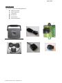
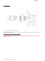
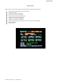
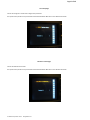
Page 1 of 15 TechSheet: 1 Rev.: 1.00 Date: 01-01-11 Model: DTW1.0 Brand: KOLIMAT Kolimat DTW Installation Guidelines General Notes Installation Steps Check the parts Installation Check V.E.D.R. Mode Kolimat USA declines any responsibility or warranty for the installation work that is not performed by Kolimat certified installers. This tech sheet is meant only as a guideline to assist customers who wish to self-install. For additional questions email: [email protected] Page 2 of 15 General Notes Read and use carefully. In this document the camera or device is commonly referred to as “DTW”. 1) Do not disassemble, repair or alter. If malfunction is due to the incorrect use or operation by the user, the warranty will be null and void and no free service will be available. 2) Do not spray liquids to clean the vehicle’s interior or use other fluids around the device as this may cause the product to malfunction and cause fire and electric shock. Avoid contact with chemicals, cleansers or moisture since they may alter the surface and/or damage the interior of the device. 3) Do not use excessive force or insert foreign objects as this may cause malfunction. 4) Do not place stickers or foreign objects on front or rear lenses of camera as this will block the view and images will not be recorded correctly. Do not place hanging and/or shiny objects around the camera, eg. around rearview mirrors. This may cause reflections and impair the quality of the recordings. 5) When installing for the first time, mount device firmly and securely. Do not relocate or move after mounting. 6) If images are saved at a different angle due to extended use or exposed to severe vibration as when driving on rough roads, adjust to original angle while stopped on flat road. 7) Do not view or operate device while driving as this may cause accidents. 8) VEDR data may not be recorded during an accident with lower than specific acceleration shock level. (Refer to Kolimat DTW User Manual - VEDR function) 9) This product’s VEDR data may not be effective in court. Contact your local government office or seek legal advice on this aspect. 10) Product may be upgraded to add on more functions and to increase customer convenience. 11) This product has built-in RTC (Real Time clock). Built-in RTC is re-set automatically depending on the GPS time information and Local Time settings. When battery for RTC is replaced, however, RTC’s time information is lost. In this case, RTC information is not accurate until the GPS antenna is connected and reception is enabled. 12) The Internal battery is designed to last an average of 10 years after production but may vary depending on use and driving conditions. Contact the company where the product was purchased if battery needs replacing. Additional cost may apply depending on the warranty period. 13) This device is designed to be used by connecting to a vehicle’s power supply. 14) This product records images on an SD Card. Some poor driving habits may decrease SD Card’s life due to frequent image recording. In case of SD Card malfunction, replace with the recommended SD card. For additional questions email: [email protected] Page 3 of 15 15) This device is designed to pass the EU and US EMI standards. However, distance between device and broadcasting reception antenna should be at least 4 inches (10 cm) since there may be interference with other devices. 16) All rights to this product’s hardware, software and data belong to the manufacturer. Unauthorized copying, processing and distribution may be subjected to compensation for damages according to civil law or to criminal punishment according to the Intellectual Property Right Protection and Management Laws. For additional questions email: [email protected] Page 4 of 15 Check the parts: The installation requires the following DTW parts: DTW V.E.D.R. device Power supply cable Junction box GPS Antenna Remote button DTW Lock/Unlock Key For additional questions email: [email protected] Page 5 of 15 Installation Prior to installation, check whether all components of the product are included, and mount in accordance with the procedures set out in the installation guide. During product installation it is necessary to mount the device with the vehicle stationary and perpendicular with the ground. The camera needs to be mounted in a location that provides an unobstructed view of the interior and exterior (front) of the vehicle. The ideal recommended position is in the middle of the front windshield under the rearview mirror perpendicular to the ground. In any case, the positioning can be executed with the aid of the device’s LCD video feedback. You should loosen the screws from the side of the DTW mounting bracket (using the supplied key). Once the desired mounting location is selected make sure that you clean and dry the windshield glass. Remove red backing from tape on the bracket and press firmly onto the glass at the desired location. With the bracket firmly in place, attach the DTW to the mounting bracket and route the RJ45 cable across the headliner then down the driver’s side A-pillar to under the dashboard. The cable should be completely concealed. Care should be taken to ensure the cable is not damaged on its way to the junction box For additional questions email: [email protected] Page 6 of 15 Power Supply Cable It is a standard 8 way internet direct (one to one) (RJ45) cable. Mounting the Junction Box The junction box should be mounted using either screws or zip-ties under the driver’s side dashboard. Care should be taken not to over tighten the screws or zip-ties as this may cause damage to the junction box. Please check the insulation between Junction Box and the vehicle body in order to avoid short circuit. Electrical Connections The device must be powered in the range 9-28Vcc. The power consumption is approx. 3W. In the under-mentioned Case descriptions the following terms will be used: +Vcc +IG : Nominal battery positive voltage : Nominal battery positive voltage present if the Ignition Switch is turned on. Vcc and IG valid voltage range is 9-28Vcc. You will need to provide wire to connect this system (approx.1-3 feet) Case 1: DTW continuously powered: Battery and Key On pins must be connected to +Vcc. Case 2: DTW power controlled by Ignition Switch Battery: pin must be connected to +Vcc Key On: pin must be connected to +IG Case 3: Device powered only when engine is on: Battery and Key On connected to +IG Common connections in all 3 Cases: Ground (x2): Ground (Connect to a known good ground source preferably bare metal in the kick panel or an existing factory ground) EXT1: Used for the systems panic button. EXT2: Typically used for a trigger input such as door, trunk or hood pin switches. EXT3: Typically used for a trigger input such as door, trunk or hood pin switches. EXTOUT: Not Used The Kolimat DTW power consumption is about 3W. The wire gauge suggested to connect the Junction Box with the vehicle’s electrical power source (power supply, external trigger) is 20 AWG (0.5 square millimeters) or 18 AWG (0.75 square millimeters). This recommendation is made mainly in order to have mechanical wire strength. If the Kolimat DTW is connected in mode 2 (ignition controlled) remember that after the engine stops (IG input unpowered) Kolimat DTW will be operative in VEDR mode for approx. 30 min and then will shut down (will go in standby mode). During this time period the Kolimat DTW power consumption is about 3W (the same of the normal operating condition). For additional questions email: [email protected] Page 7 of 15 Connection diagram: External fuse is suggested but not absolutely necessary. The Junction terminal has a PTC that protects the power cable and Kolimat DTW device. The PTC component works as ‘solid state fuse’ and does not require maintenance. Optional external fuse type: 1A or 1.5AA time-delayed (T type) Warning: Do not use fast type fuse (F type), because the DTW’S internal backup battery requires a high current for a few milliseconds at power on. For additional questions email: [email protected] Page 8 of 15 Panic Button Installation Mount the panic button in a location that is approved by the customer before you start the installation. There are two wires for the panic button. One will get connected to EXT1 on the junction box and the other will be connected to ground. Mounting the GPS Antenna When installing the GPS antenna on a vehicle, be sure that the side labeled GPS is pointed toward the sky, preferably in the center of the dashboard. For the GPS receiver to accurately compute its location, its antenna must have a clear view of the sky. Equipment such as an air horn or marker lights should not block the antenna beyond 5° above the horizon. When the Kolimat DTW is powered on, the GPS signal level can be checked in the LCD diagnostic pages 1 and 2. For additional questions email: [email protected] Page 9 of 15 Check DTW Operativity When the DTW is powered on, the device executes the boot sequence and then starts in VEDR operating mode: Boot sequence The internal infrared LED’s must be turned on (a low red light can be detected from all the 6 internal IR LED’s) The LCD displays the boot sequence page (boot animation, Kolimat logo, wait message….) If enabled, the buzzer warning for the condition: device ready (3 beep sequence) VEDR Operating Mode The LCD displays the default page (NOTE, the page can be also a ‘blank’ page based on the device setup) The keyboard allows the selection of the previous or next page using the left or right button Diagnostic Pages Blank page The blank page can be used in order to have the minimum light interference between the driver and the LCD backlight. Front camera view The external view page permits the view of the real-time image acquired by the front camera Internal camera view The internal view page permits the view of the real time image acquired by the rear camera (if enabled) For additional questions email: [email protected] Page 10 of 15 Diagnostic page 1 Displays the common information status bar (described below) and the following diagnostic info: GPS Coordinates & Speed (if GPS receives a valid signal) Frames per sec value Critical event number (recorded/total) Normal event number (recorded/total) Record Button event number (recorded/total) Trigger 1 event number (recorded/total) Trigger 2 event number (recorded/total) Trigger 3 event number (recorded/total) Power supply voltage value ( must be some volts above the nominal battery voltage) Ignition key status SD Card free space For additional questions email: [email protected] Page 11 of 15 Diagnostic page 2 Displays the common information status bar (described below) and the following diagnostic info: Internal camera status External camera status Audio channel status WLAN Status WLAN Configuration parameters (cycled) Kolimat DTW reference parameters (cycled) For additional questions email: [email protected] Page 12 of 15 Diagnostic page 1 & 2 common info Diagnostic pages 1 and 2 display an upper and bottom common information bar that shows the following data: Upper bar: o Power supply status ‘Power’ label is displayed in: Red background - if power supply is lost (backup battery power supply) Green background - if power supply is good o System vitality o Label ‘*’ blinks if the system is running o Event recording status Label related to the source event is displayed if the related event is detected and the event recording is currently active. o GPS Signal status and level Label ‘GPS-“ is displayed if the GPS cable is not connected or GPS is not working correctly Label ‘GPS1” to “GPS5” are displayed based on the GPS signal level detected GPS1 means minimum signal level, GPS5 means maximum signal level o WLAN Communication Status Label ‘WL:-” is displayed if the WLAN signal is not detected Label “WL:0” to “WL5” are displayed based on the WLAN signal level WL0 means WLAN minimum signal level, WL5 means maximum signal level o USB Communication Status Label “USB” red background is displayed if the USB cable connection is not detected Label “USB” green background is displayed if USB cable connection is detected Bottom bar o Vehicle plate number o RTC subsystem Date-Time Note: The DTW Real Time Clock is automatically updated when a valid GPS signal is received. The Date/Time is adjusted based on the local time settings. For additional questions email: [email protected] Page 13 of 15 Local Setup Page Permits the change of a subset of the configuration parametersThe specific access password is required. Please read Kolimat DTW User Manual for more detailed information. SD Secure removal page Permits the safe SD Card removalThe specific access password is required. Please read Kolimat DTW User Manual for more detailed information. For additional questions email: [email protected] Page 14 of 15 Verification of proper operations Remote button verification Assuming that the remote button is connected to External trigger 1 A similar procedure can be used if the remote button is connected to external trigger 2 or 3. In this case the installer must check the data related to the External trigger used. Select the diagnostic page 1 1. Read the event number displayed in the “Ext. Trig. 1“ field The data is in the form: xxx/yyy, xxx: is the current number of “External Trigger 1” events recorded, yyy: is the maximum number of Trigger 1 events in the recording queue 2. 3. Press the remote button Verify the following DTW behavior: The green led start to blink The buzzer sound series is produced (if enabled via setup) The LCD diagnostic page 1 “Ext. Trig. 1, starts to blink The “Ext.Trig. 1” event recorded count is increased by 1 After about 20 sec the green LED switches off and ‘Ext. Trig. 1’ diagnostic page 1 label stops blinking. Recording button verification The recording button is the red button in the bottom part of the Kolimat DTW camera body. Select the diagnostic page 1 1. Read the event number displayed in the “Man. Rec.” field The data is in the form: xxx/yyy, xxx: is the current number of “Manual Recording” events recorded, yyy: is the maximum number of Manual Recording events in the recording queue 2. 3. Press the red REC button Verify the following DTW behavior: The green led starts to blink The buzzer sound series is produced (if enabled via setup) The LCD diagnostic page 1 “Man. Rec.” label starts to blink The “Man. Rec.” event recorded count is increased by 1 After about 20 sec the green LED switches off and ‘Man. Rec.” diagnostic page 1 label stops blinking. For additional questions email: [email protected] Page 15 of 15 Crash events simulation This test should be performed only if the operating conditions allow, on a road test, using the utmost care and safety precautions. Target of this test is to simulate a ‘Normal’ or ‘Critical’ event. Select the diagnostic page 1 1. Read the event number displayed in the “Normal” and “Critical” fields The data is in the form: xxx/yyy; xxx: is the current number of “Normal” or “Critical” events recorded, yyy: is the maximum number of “Normal” or “Critical” events in the recording queue 2. 3. Accelerate the vehicle to medium speed (from 10 to 20 MPH) and then press the brake pedal quickly so as to make a sudden stop Verify the following DTW behavior: The green led starts to blink The buzzer sound series is produced (if enabled via setup) The LCD diagnostic page 1 “Normal” or “Critical” label starts to blink The “Normal” or “Critical” event recorded count is increased by 1 After about 20 sec the green LED switches off and the “Normal” or “Critical” diagnostic page 1 label stops blinking. For additional questions email: [email protected]