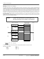
1
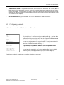
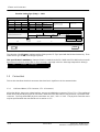
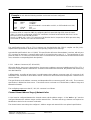
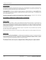
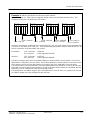
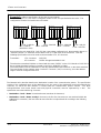
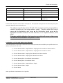
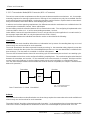
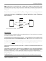
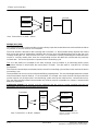
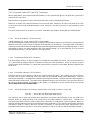
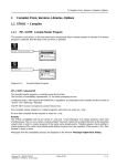
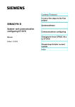
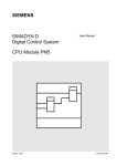
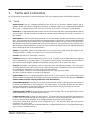
2 Terms and Connectors
1
Terms and Connectors
As an introduction to the world of communication terms, the most important terms will be initially explained:
1.1
Terms
~
Address Stage: Part of a configuring definition at the AT, AR or US connector (address stage 1 and 2).
Address stages must only be configured in serial links; no address stage is to be configured for parallel links
‘‘Rack Link’’, ‘‘Coupling Memory Link’’and ‘‘PN Local Link’’(see section ‘‘Connectors’’in this chapter).
~
Board ID: All configured board names must be exactly 6 characters long when configuring networks (peer to
peer or routing). The 6th character must adhere to a predescribed convention (see section ‘‘Connectors’’in
this chapter).
~
Data Interface: Fixed structured memory medium (i.e. Dual Port RAM), via which two link partners exchange
data. The organization or structure defines how the data interface is layed out (i.e. where general initialization
data are located, how many memory areas are available either in total or are still current) The layout of the
data interface is the same for all links, that can be processed by P32. The organization of the contents of the
data interface is without significance for the user, since in general no memory areas are explicitly addressed
when configuring the link or the communication.
~
Utilities: Configurable, closed functionalities with one or several access points to the data interfaces (i.e.
message systems). A utility can consist of one or several function blocks.
~
Receiver: See the term ‘‘Transmitter / Receiver’’.
~
Firmware: Sequence control on a link board, such as CSH11. Firmware is not configured with the configuring
tools in SIMADYN D (i.e. not with STRUC). The firmware is set the task of converting the user data from the
data interface into a telegram with the corresponding current protocol (or of course vice versa).
~
Channel: Area within a data interface, which is reserved for two communication partners. This area can be
created by either the transmitter or the receiver. When the link partner is firmware, then this are must always
be created by the transmitter or receiver (and not by the firmware).
A channel always consists of channel management and one or two user data buffers.
This area cannot be explicitly accessed by the designer.
~
Channel Name: Part of a configuring definition at the AT, AR or US connector. The channel names must
always be defined and permit the transmitters and receivers to find their communication partners. Therefore
channel names must be uniquely defined for each data interface.
~
Channel Management: The section of a channel via which two link partners communicate to one another as
to how the user data buffer is to be interpreted. This area contains, for example, whether new user data is
currently being inserted or has already been inserted or the previous data has already been read etc.
This area cannot be accessed by the designer.
~
Communications Partner: Partner that further processes the user data. This can be a transmitter / receiver
within SIMADYN D or also in another system / device.
~
Communications Port: Location of a data interface. This means the board on which the data interface is
located. Since several boards with the same type (i.e. two CS11) can be configured in the same rack, then a
board can only be clearly identified via its configured board name in the Master program.
A maximum of three data interfaces can be configured in CS7. The allocation takes place via the front
connectors X01, X02 or X03.
Therefore a communications port is identified either by a configured board name or a configured board name
and a connector number (X01 etc.).
Siemens AG 465 980.7107.22
SIMADYN D Configuring Manual Communication
Release 02.96
2--1
2 Terms and Connectors
~
Link Partner: Partner in SIMADYN D, with which data is exchanged via a data interface. This is always a
receiver or firmware for a transmitter and always a transmitter or firmware for a receiver. The link partner is
simultaneously also the communications partner in a rack link, when in one rack the transmitter has been
configured and the receiver has been configured in another.
Firmware is always the link partner to a transmitter, to a receiver or to another firmware. Firmware cannot be a
communications partner (since it processes no information, but rather implements the protocol conversion;
i.e. between SIMADYN communication and SINEC H1).
~
Link Board: Board with memory or direct access to memory (CS21), onto which a P32 inserts the data to be
transmitted or from which the data is extracted by a P32. Link boards are the CSH11, CS11, CS21 and CS7 as
well as all link memories (MM11, MM21, MM3, MM4) and the signal processor board EP22. The P32 is
simultaneously also the link board for the PN local link, since the data interface is located on the P32 and only
local processor accessing is made to this data interface.
~
Link Type: Designation of the link, i.e. SINEC H1, rack link, DUST1.
~
User Data: Pure processing variables, that are transmitted from a transmitter to a receiver. The user data
does not contain any information regarding type, sequence or contents of the processing variables.
~
User Data Structure: Information concerning the structure of the transmitted user data. The user data
structure describes the data types and the number of the same data types in sequence. This is a check
criterion for the transmitter and receiver synchronization. The user data structure cannot be configured, but is
automatically created by the transmitters / receivers (see chapter ‘‘Terms and Connectors’’).
~
Buffer / User Data Buffer: The section of a channel in which the user data is transmitted.
This area cannot be accessed by the designer.
~
Reorganization: Reformatting a data interface during on-line operation. All link central blocks possess a
CDV connector (B1 type). When a positive edge occurs at this connector, then the central block disables the
link and reformats the data interface after approximately 10 seconds. Subsequently the data interface is
re-enabled.
All transmitters / receivers and also firmware revert to a wait state during the disabled and reformatting period.
The reconnect and synchronization of all channels occurs, as during a system start-up, after the renewed
enable.
The functionality is required to make ‘‘Space’’on a data interface. This is however only possible when a peer
to peer network is configured (see chapter ‘‘Communication Method of Operation’’).
~
Transmitter / Receiver: Function blocks that have write and or read access to one or several data interfaces.
A transmitter is, for example, the function block MSI, receiver the function block CRV and both simultaneously
is the function block SER.
~
Telegram Name (Only P16): The telegram name is required when differing communication blocks are to
gather their user data into one telegram for the indirect communication. The telegram, managed by a
telegram block or possibly a central block, is clearly identified by the telegram name. Connectors for telegram
names are:
-- CCT TR
-- CCR RR
-- COP OR
‘‘Transmit Telegram Name’’
‘‘Receive Telegram Name’’
‘‘Dialog Telegram’’
Telegram names must be defined in both the configured entries at the corresponding block and
also in the Master program, whereby each telegram name at this location must be supplied with
the sampling time definition of the telegram or central block. The telegram name and sampling
time are required, so that the STRUC compiler can determine which transmit / receive blocks from
the permanent FP are to operate with which telegram blocks in the special communications FP
and whether the sampling times are identical; thereby guaranteeing data integrity. The Master
program is used by the STRUC compiler as an intermediate memory, since an FP cannot be
compiled with another FP, but can always be compiled with the Master program.
2--2
Release 02.96
Siemens AG 465 980.7107.22
SIMADYN D Configuring Manual Communication
2 Terms and Connectors
~
Transmission Mode: Configurable transmission mechanism for the transmitter and receiver (MOD or
MOx connector in the transmitter / receiver). A selection is possible between the modes Handshake, Refresh,
Select and Multiple. The transmitter and receiver must be configured with the same transmission mode;
otherwise they will not be able to synchronize with one another and subsequently exchange data (see section
‘‘Connectors’’in this chapter).
~
Access Mechanisms: Type and method of accessing data interfaces without collisions.
1.2
Configuring Remarks
1.2.1
Communications FP’s Receive and Transmit
SHEET
Load ...
Find ...
Insert ...
Delete ...
Attach ...
Page Down ...
FB Display from ...
Text Panel ...
Comments Panel
Process FP 1 ...
Process FP 2 ...
Process Macro ...
Convert FP-> Macro ...
Convert Macro->FP ...
Set Macro Parameters ...
All central blocks, i.e. all function blocks starting with ‘‘@..’’, will be either
configured in the communications FP receive or transmit. If they are
configured in other function packets, then the compiler run will terminate
(FP COMP or AUTOCOMP in the basic dialog) with an error message.
The function packet names for communication FP receive and transmit
also start with ‘‘@...’’and are configured in the Master program in the
menu item ‘‘Module Parameter Drawing ...”.
A specification is mandatory in the FP type text panel for both
communications FP’s.
The text panel is selected in the function packet editor, i.e. in the block
configuring level, in the upper menu strip (see left-hand diagram).
The following window is popped onto screen after selecting the text panel:
Siemens AG 465 980.7107.22
SIMADYN D Configuring Manual Communication
Release 02.96
2--3
2 Terms and Connectors
Function Packet Type (Entry) = COM
Current Drawing
SIMADYN D/STRUC V4.2.1
FP : 28. 03. 95 14:49
MP : 16.03.95 14:32
A
17. 12. 94
AB
Date
17.12.95
B
15. 03. 95
CD
Modified
ASI 1 R
01. 04. 95
EF
Checked
Name
Standards
C
Status
Version
B:
Date
CHK
C:
FBSLIB 921012V400
A:
Siemens AG
SIMADYN--- D V4.2.1
STRUC--- G Example
Siemens AG
STRUC User
Urspr./Ers. f./Ers. d. FP--- SAEG32 from 17. December 1993
PJ--- PJV420
MP--- HANDMP
Test Configuring
Example Saw Tooth Function
PN--- DO1_P1
FP--- SAEG32
=DB50, WOO
+H7
(3) EB831--- G4569---
Funktionsplan/Function chart
Sheet
K001
Pg.
FP--- Typ
Zeichn. Nr./Drawing No. List
sco06t11
v421
rupprech
FP:
OK
94) E8831--- G4569---
K002
SL:
Cancel
The selection of the FP type is implemented by clicking on the ‘FP Type’panel with the left-hand mouse key. Then
select the FP type ‘‘COM’’from the pop-up menu.
This specification is mandatory. If no specification is made, then the FP--COMP or AUTOCOM function runs will
be terminate in the basic dialog with an error message ( message in the box ‘‘Message Output Basic Dialog’’):
****
1.3
1 Error
0 Warnings
Connectors
This section describes the block connectors that have basic significance in the communication.
1.3.1
Link Board Name (CTS Connector, CT1..4 Connector)
All function blocks, that access a data interface, possess an initialization connector CTS or CT1..4. The configured
board name and possibly the physical connection, under which this data interface may be found, is specified at this
connector. The only permissible physical connections are ‘‘X01’’, ‘‘X02’’or ‘‘X03’’. The physical connection must
only be specified when the data interface is located on a CS7.
2--4
Release 02.96
Siemens AG 465 980.7107.22
SIMADYN D Configuring Manual Communication
2 Terms and Connectors
Example: A rack with the following modules and names has been configured:
Slot
S01
S03
S04
Module
PM3
MM11
CS7
S06
S07
CSH11
PT32
Configured Name
‘‘D01_P1
‘‘COUPLE”
‘‘COMM1”
(An SS4 module is connected to an X01, an SS5 module to an X02)
‘‘H1”
”TEC_P2”
If a PN local link is created on PM3 (by configuring the link central block @CPN), then the name
‘‘D01_P1’’must be configured at all the CTS connectors of all their function blocks that ‘‘Run’’on the
PM3 and are to access the PN local link.
Specify ‘‘COMM1.X01’’at the CTS connector of all function blocks, irrespective of which processor they
are located on, that are to access the SS4 module.
The specifications at the CTS or CT1..4 connector are checked during the STRUC compiler run (PN_COP).
Impermissible specifications will lead to the corresponding compiler error message.
A permissible specification is also a ‘‘0’’(Null). This specification will cause all transmitters / receivers with only one
CTS connector to generate a communications error (if no board has the name ‘‘0’’!). The specification is only
practical at the CT1..4 connectors of the CDC4 and CC4 function blocks (not all interfaces must be allocated in this
case; review the corresponding block descriptions).
1.3.1.1 Address Connectors (AT, AR and US)
All function blocks, that access a data interface, also possess an address connector in addition to the CTS or CT1..4
connector (exception: the link central blocks -- these do not transmit and receive data, they initialize and monitor only
one data interface).
A differentiation, according to board type, is made between three address connector types: AT connector for all
transmitters, AR connector for all receivers and US connector for all function blocks that process a transmit and a
receive channel.
The specifications at the address connector are independent of the connector type (AT, AR or US). The connector
specification is divided into three areas. These three areas are known as Channel Name, Address Stage and
Network Information.
The configuring sequence at the AT / AR / US connector is as follows:
Channel Name.Address Stage.@Network Infos
A ‘‘dot’’must be configured between the channel names and the address stages. A ‘‘dot’’and an ‘‘@”’’must be
configured between the address stages and the network infos. The dots and the @ character are required as
identification criteria for the connector evaluation.
The channel name must always be configured. Address stages and network infos are optional specifications.
Siemens AG 465 980.7107.22
SIMADYN D Configuring Manual Communication
Release 02.96
2--5
2 Terms and Connectors
Channel Name:
The data interface, to which a function block is to have access, is specified at the CTS connector. The data area (i.e.
the channel), via which the user data is to be exchanged with a data interface, is allocated a channel name. The
transmitter and receiver will find each other via this channel name.
A prerequisite is of course, that the channel name on a data interface is unique and that the
transmitter and receiver have been configured with the same channel name. The designer has
sole responsibility for this.
The channel name maybe a maximum of 8 characters long. All ASCII characters, except the ‘‘dot’’and the @
character are permitted. The name can be selected otherwise without restrictions.
The multiple configuring of a channel name is not checked.
Address Stages:
Several links, such as the SINEC L2 FMS, require additional information for data transmission. This information can
differ greatly, dependent upon the type of link and is therefore link specific. They are known as address stage 1 and
address stage 2 for SIMADYN D. All address stages are separated by a ‘‘dot’’. Which or whether a specification is
required, can be reviewed in the Chapters dealing with the individual links (for example, no address stages need to
be specified for the rack link).
The specification of address stage 2 without address stage 1 is not possible. If only one address stage is specified,
then this is always the 1st address stage.
Address stage 1 maybe a maximum of 14 characters long. Address stage 2 has a maximum length of 16 characters.
Network Infos:
The functionality ‘‘Peer to Peer Network’’is available within the SIMADYN D network. The data transmission
between transmitters and receivers over several racks is thereby made possible (see Chapter ‘‘Network’’). In order
to even find the ‘‘Remote’’link partner, information is necessary to describe its location (i.e. rack + board +
connector); to permit the communication partner to connect its channel.
The Network Infos must only be configured when utilizing the peer to peer network.
2--6
Release 02.96
Siemens AG 465 980.7107.22
SIMADYN D Configuring Manual Communication
2 Terms and Connectors
Example 1: Address specification for the peer to peer network.
The module types (i.e. P32) and the configured module names are specified below the racks. The
configured rack name is located in the rack header.
A100
A200
CS11 : D18CSB
P32 : D01_P1
A300
A400
CS11 : D2ACSB
CS11 : D38CSB
CS21 : C26CSB
CS21 : C37CSB
P32 : D48_P2
CS21 : D47CSB
Assume a transmitter is configured on the rack A100 (P32 : D01_P1), that wishes to exchange data with
a receiver on rack A400 (P32 : D48_P2). Then the following specifications must be made at the CTS, AT
and AR connectors of the transmitter and receiver:
Transmitter:
CTS Connector:
AT Connector:
‘‘D18CSB”
‘‘[email protected]”
Receiver:
CTS Connector:
AR Connector:
‘‘D47CSB”
‘‘[email protected]”
The above example shows that a transmitter initializes a channel with the name ‘‘DATA1’’on the CS11
data interface ‘‘D18CSB”in the rack A100. The receiver initializes a channel with the same name on the
CS21 interface ‘‘D47CSB”(the data interface is located on the CS11 ‘‘D38CSB”) in the rack A400.
The network takes over the initialization of the data path between both interfaces on the A100 and A300.
If now the user data length and the structures as well as the transmission mode are compatible, then the
initialization can be completed and the data exchange started.
The specifications for address stage 1 and 2 are omitted here, since all racks are coupled via a rack link
(no address stages are to be configured for the rack link).
Siemens AG 465 980.7107.22
SIMADYN D Configuring Manual Communication
Release 02.96
2--7
2 Terms and Connectors
Example 2: Address specifications for the peer to peer network.
The module types (i.e. P32) and the configured module names are specified below the racks. The
configured rack name is located in the rack header.
A100
A200
CS11 : D18CSB
CS7 : D16D1C
(with SS4 in X01)
A300
A400
CS11 : D2ACSB
CS11 : D38CSB
CS21 : C26CSB
CS21 : C37CSB
P32 : D48_P2
CS21 : D47CSB
Assume that the rack A400 (P32 : D48_P2) has a transmitter configured on it, that transmits data to an
‘‘External’’partner (i.e. SIMOVIS) via the DUST1 link (CS7 with SS4) in the rack A100. Then the
following specifications are to be made on the transmitter CTS, AT connector:
Transmitter:
CTS Connector:
AT Connector
‘‘D47CSB”
‘‘[email protected]”
Therefore the transmitter initializes a channel with the name ‘‘DATA1”on the CS21 interface ‘‘D47CSB”in
the rack A400 (the data interface is located on the CS11 ‘‘D38CSB”in A300).
The network takes over the initialization of the data path between both interfaces on the A100 and A300.
The specification for the address stage 1 at the AT connector (‘‘100”) is necessary, since the address
stage 1 must be configured at DUST1.
The Network Infos describe therefore the destination location of the communication partner. The specification
consists of the configured name of the destination rack, the name of the destination board and optionally the
connector, on which the data interface is located with the communication partner channel. The three
sub-specifications (rack name, board name and physical connection) must be separated by a ‘‘dot’’. The
specification must start with the @ character:
-- Destination -- Rack -- Name: Unrestricted name (maximum 6 characters).
-- Destination -- Rack -- Name: exactly 6 characters; the first five characters are not restricted (within the
SIMADYN D convention), the last character must describe a unique board ID according to the following
allocation:
2--8
Release 02.96
Siemens AG 465 980.7107.22
SIMADYN D Configuring Manual Communication
2 Terms and Connectors
Board ID (0...F)
Board Type
Boards
1 -- 8
P32 (and P16)
PM3, PT31, PT32
A
Coupling Memory
MM11, MM3, MM4, MM21
B
Rack Link
CS11, CS21
C
For Serial Links
CSH11, CS7
0, 9, D -- F
Unassigned
Can be allocated for all boards not
specified here
The board ID is important for the network management. This expedites routing of transit channels (in peer to peer
networks) dependent upon the board types.
.
The address specification at the AT / AR / US connector must be unique within a
network (exception is a two stage address stage). Therefore either the channel
name, or the destination rack name or the destination board name or the
destination interface between the two channels, on a request interface, must
differ!
Otherwise multiple utilization of a channel occurs which will sooner or later cause
the channel to be blocked or the system to crash.
Combinations of all Possible Address Specifications:
The following address specification combinations are therefore possible due to the differing sub-specifications at an
address connector AT, AR or US:
1.) Channel Name.Address Stage1.Address Stage2.@Rack Name.Board Name.Interface
2.) Channel Name.Address Stage1.Address Stage2.@Rack Name.Board Name
3.) Channel Name.Address Stage1.@Rack Name.Board Name.Interface
4.) Channel Name.Address Stage1.@Rack Name.Board Name
5.) Channel Name.@Rack Name.Board Name.Interface
6.) Channel Name.@Rack Name.Board Name
7.) Channel Name.Address Stage1.Address Stage2
8.) Channel Name.Address Stage1
9.) Channel Name
Other specification combinations are not possible.
Siemens AG 465 980.7107.22
SIMADYN D Configuring Manual Communication
Release 02.96
2--9
2 Terms and Connectors
1.3.1.2 Transmission Mode (MOD Connector, MO1..4 Connector)
The various communication requirements act directly upon the data transmission mechanisms. It is, for example,
extremely important for message systems that no message is lost (new data may only be transmitted after the
previous data has been acknowledged). On the other hand the control of devices, requires that the newest data is
always transmitted (newest data without acknowledging the previous).
In order to service these opposing requirements, four different transmission mechanisms are available for the P32
communication: Handshake, Refresh, Select and Multiple.
Several utilities permit the selection between all four transmission modes. The configuring is implemented at the
connector MOD or MOx (x=1...4) of the corresponding transmitter / receiver.
Other utilities, however do not permit selection, since it is only practical to run the application in a certain mode (i.e.
the message output block MSI can only be operated in the mode ‘‘Select’’).
The differences between the individual transmission modes are described in the following:
Handshake:
This transmission mode should be utilized when no information loss by means of overwriting data may occur and
when exactly one receiver exists for each transmitter.
The mode ‘‘Handshake’’describes sequential channel processing, i.e. the transmitter always deposits a new data
set into the channel after the receiver has acknowledged the previous set. One user data buffer is available for the
data exchange. The data traffic is controlled via channel management.
The user data is inserted into the channel in one working cycle and extracted by the receiver in one working cycle.
The transmitter and receiver can be configured in differing sampling times. The user data length must be identical
between the transmitter and receiver, i.e. the transmitter must never transmit, for example, 100 Bytes and the
receiver expect only 50 Bytes (is checked during system start-up and could lead to a communication error).
The user data structure between the transmitter and receiver must be compatible (see chapter ‘‘Communication
Method of Operation’’).
Transmitter
KVL
Receiver
NDP
Data Transmission in Mode ‘‘Handshake’’
KVL = Channel Management
NDP = User Data Buffer
Refresh:
This transmission mode must be utilized when a receiver always requires the newest data to be made available and
when exactly one receiver exists for each transmitter.
The mode ‘‘Refresh’’describes a data exchange with ‘‘Overwrite’’, i.e. the transmitter always inserts the newest data
sets into the channel, independent of whether the receiver has acknowledged the previous data set or not.
2--10
Release 02.96
Siemens AG 465 980.7107.22
SIMADYN D Configuring Manual Communication
2 Terms and Connectors
Two user data buffers are available for the data exchange, and are utilized as an alternating buffer system
(transmitter indicates which buffer contains the newest data). The data traffic is controlled by channel management.
The transmitter inserts the user data into the channel in one working cycle and is extracted by the receiver in one
working cycle.
The transmitter and receiver can be configured in differing sampling times. The user data length between the
transmitter and receiver must be identical, i.e. the transmitter, for example must never transmit 100 bytes, when the
receiver expects only 50 bytes (is checked during system start-up and could lead to a communication error).
The user data structure must be compatible between the transmitter and receiver (see chapter ‘‘Communication
Method of Operation’’).
KVL
Transmitter
Receiver
NDP1
NDP2
Data Transmission in Mode ‘‘Refresh’’
Select (Only P32):
This transmission mode must always be utilized, when no data loss by means of data overwrite may occur and when
any number of transmitters exist for one receiver.
The mode ‘‘Select’’describes sequential channel processing, i.e. the transmitter always inserts a new data set into
the channel after the receiver has acknowledged the previous set. One user data buffer is available for the data
exchange. The data traffic is controlled via channel management.
All configured transmitters utilize the same user data buffer. A transmission sequence for the transmitter does not
exist. The first to initiate will be permitted to transmit, if the receiver has already acknowledged the previous data set.
In order to achieve a controlled data transmission, only one transmitter is permitted to be ‘‘Enabled’’
(EN connector = 1).
The user data is inserted into the channel by the transmitter in one working cycle and extracted by the receiver in one
working cycle.
The transmitter and receiver can be configured in differing sampling times. The user data length must be identical
between all transmitters and the receiver, i.e. a transmitter must never, for example, transmit 100 bytes and the
receiver expect only 50 bytes (is checked during system start-up and could lead to a communication error).
The user data structure between the transmitter and receiver must be compatible (see chapter ‘‘Communication
Method of Operation’’).
Configuring Remark: The transmitters must be configured in a smaller sampling time than the receiver !
Siemens AG 465 980.7107.22
SIMADYN D Configuring Manual Communication
Release 02.96
2--11
2 Terms and Connectors
Transmitter 1
KVL
Receiver
Transmitter 2
....
NDP
Transmitter n
Data Transmission in Mode ‘‘Select’’
Multiple (Only P32):
This transmission mode is to be used when receivers always expect the newest data to be made available and when
any number of receivers exist for one transmitter.
The mode ‘‘Refresh’’describes a data exchange with ‘‘Overwrite’’, i.e. the transmitter always deposits the newest
data set into the channel, independent of whether the receivers have acknowledged the previous data set or are
currently reading this set. If the receiver is too slow, i.e. a transmitter is already overwriting the same buffer that a
receiver is currently reading from, then the corresponding receiver will detect this and discard the previously
received data. The receive operation is repeated in the next working cycle.
Two user data buffers are available for the data exchange, and are utilized as an alternating buffer system
(transmitter indicates in which buffer the newest data is located). The data traffic is controlled via a channel
management.
The user data is inserted by the transmitter into the channel in one working cycle and the receiver extracts the data in
one working cycle.
The transmitter and receiver can be configured in differing sampling times. The user data length between the sender
and all transmitters must be identical, i.e. the transmitter, for example, must never transmit 100 bytes when the
receiver expects only 50 bytes (this is checked during system start-up and could lead to a communication error).
The user data structure between the transmitter and receiver must be compatible (see chapter ‘‘Communication
Method of Operation’’).
Configuring Remark: The receiver must be configured with the same or smaller sampling time than the
transmitters (the receiver must therefore operate faster).
Transmitter
KVL
Receiver 2
....
NDP1
Receiver 1
NDP1
Receiver n
Only one arrow is shown to the
receivers, in order to simplify the
diagram overview
Data Transmission in Mode ‘‘Multiple’’
2--12
Release 02.96
Siemens AG 465 980.7107.22
SIMADYN D Configuring Manual Communication
2 Terms and Connectors
1.3.1.3 Firmware Status (ECL and ECO Connectors)
All link central blocks, that communicate with firmware (i.e. the central blocks @CSD1 or @CSH11), possess the
connectors ECO and ECL.
Both connectors only appear in pairs and indicate the status of the corresponding firmware.
When ECL=0 and ECO=0, then the firmware is in an error free state. When ECL=0 and ECO>0, then an error has
occurred, that can be resolved by the designer or user. When ECL>0 and ECO>0, then an unresolvable error has
occurred.
The exact values when ECL=0 and ECO>0 can be reviewed in the chapters dealing with the individual links.
1.3.1.4 User Data length (LT / LTW Connector)
‘‘Length Telegram’’(LT = byte number; LTW = word number).
The specified telegram length must be large enough to satisfy all indirect transmit / receive blocks configured to this
telegram (ensure the correct connector formats of the transmit / receive blocks ! The specification must always
conform to the transmit and receive telegram block (guarantee against transmission and configuring errors). It is not
permissible to specify any other length than the actual required length (i.e. for test purposes or for successive
configuring expansions). The specification is link type specific.
1.3.1.5 Transmission Status (QTS Connector)
This status signal reverts to 1, when a telegram / user data was transmitted or received. This connector reverts to
‘‘0’’, if the number of telegram failures in sequence reaches the LEM specification. At the occurrence of grave
communication errors (flashing ‘‘C’’) or when the communication connection is interrupted, then this output will also
be set to ‘‘0’’.
1.3.1.6 Error Status Indicator (YTS Connector)
The block outputs an accurate error code for the current transmission status. This includes not only real (grave)
run-time errors, but also configuring errors that could only be detected during system initialization. They are
indicated as a flashing ‘‘C’’on the processor module seven segment indicator. The error code also shows temporary
status indications and warnings. The output value is deleted when the cause is removed. The connector value can
be read as a decimal number, for example, by the monitor. It’s significance can be reviewed in the user manual
‘‘Error Diagnostics PM Communication’’.
1.3.1.7 User Data Sequence for Indirect Communication (PFP / PFB Connectors, Only P16)
PFP O2 -- ‘‘Place (the User Data) with respect to FP”
PFB O2 -- ‘‘Place (the User Data) with respect to FB”
The arithmetic sum of these two specifications determines the location (offset in bytes) of the user data in the
telegram buffer of a telegram block to be processed by the indirect transmit / receive block. Therefore two
connectors have been created in order to improve the schematics and sub-division of the configuring. When, for
example, the same indirect transmit / receive blocks are to be configured in 2 FP’s, then the specifications at the PFB
connectors in both FP could be the same; all that is required is to enter the total space requirements of the
transmit/receive blocks of the first FP at the PFP connectors of the second FP (review the following example !).
Siemens AG 465 980.7107.22
SIMADYN D Configuring Manual Communication
Release 02.96
2--13
2 Terms and Connectors
Warning: Avoid data area overlapping !
The buffer requirements of the individual indirect transmit / receive blocks must be accurately estimated during
configuring. Special care must be taken with the connector types: the frequently utilized N2 type (16 bit, i.e. CTD1,
CTD2, CTD4) require 2 byte of the telegram buffer for each connector. It cannot be detected when the specified
offset in the telegram is too small; the receiver will then process incorrect data unnoticed! On the other hand it is
permissible to define data areas with gaps, as long as the telegram length specified at the LT connector is not
exceeded. The empty intermediate areas within the telegram are then not defined, in general they will contain ‘0’.
Recommendation: Utilize transmit / receive blocks that process only 1 byte user data (CTD81), these should be
located at the end of the telegram buffer so that the other word processing blocks can place their user data on even
addresses (review the following example).
Example:
3 similar indirect transmit blocks in 2 function packets FP1
and FP2. One byte is left free behind the CTD81, such that
the following data words can be located on even addresses.
Telegram Buffer
(Byte for Byte)
Indirect Transmitter
Free
0
1
2
3
4
5
6
7
Free
8
9
10
11
12
13
14
15
CTD1 PFP -- 0
2 Byte PFB -- 0
FP1
CTD14 PFP -- 0
PFB -- 2
4 Byte
CTD81 PFP -- 0
1 Byte PFB -- 6
CTD1
2 Byte
FP2
PFP -- 8
PFB -- 0
CTD14 PFP -- 8
PFB -- 2
4 Byte
CTD81 PFP -- 8
1 Byte PFB -- 6
Offset
Diagram: PFB / PFP Utilization
A different specification of the offset in FP2 is also possible and leads to the same result:
All Indirect Transmitters:
CTD1:
CTD14:
CTD81:
2--14
PFP
PFB
PFB
PFB
-----
0
8
10
14
Release 02.96
Siemens AG 465 980.7107.22
SIMADYN D Configuring Manual Communication
2 Terms and Connectors
1.3.1.8 Error Message Limit (LEM Connector, Only P16)
Specify here how many sequential invocations of the transmit / receive blocks, by which no telegram transfer was
registered, can occur before the transmission status indicating status signal at the output ‘‘QTS B1’’is switched from
‘‘Not Faulty (1)’’to ‘‘Faulty (0)’’. This is currently the only possibility in SIMADYN D to indicate faulty telegram
transfers to the configuring shell and also is only practical for cyclically configured telegrams. Therefore the basis for
monitoring is a cyclic telegram transfer. The cyclically operating telegram block (sampling time) also check whether,
at its invocation, a free (transmitter) or filled telegram buffer (receiver) is available. When a data transmission control
cannot transmit telegrams, i.e. due to a line break in a DUST, then the transmit buffer cannot be emptied. When, on
the other hand, no new telegram has been received within a sampling times, then no new buffer can be filled for the
receive blocks. The number of sequential telegram failures (or non available buffers), after which an error is
indicated, is specified at this connector. The different cycle times between the block and telegram transfer must be
taken into account in this number.
Example:
Telegrams are received in a 50ms cycle. The receive blocks are processed in a 16ms sampling time, since the
blocks can be more conveniently configured into the processing or since the dead time between the receiving and
the processing is to be reduced.
Therefore the block always sees at least 2 sequential ‘‘Telegram Failures’’. Therefore configure at least the number
3 at the LEM connector, in order to maintain a functioning transmission. As soon as one telegram has been
successfully transferred, then the transmission status (QTS) is set to ‘‘Not Faulty’’, independent of the current LEM
number. The internal failure count then starts again. The specification 0 disables the error message via the QTS
connector, with 1, each individual telegram failure is reported. This can be therefore utilized to structure a simple
telegram handshake. Therefore review the QTS connector !
Siemens AG 465 980.7107.22
SIMADYN D Configuring Manual Communication
Release 02.96
2--15
2 Terms and Connectors
2--16
Release 02.96
Siemens AG 465 980.7107.22
SIMADYN D Configuring Manual Communication