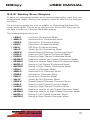
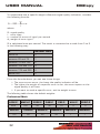
1
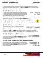
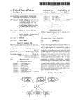
DIGIspy
Background photograph ã Dieter Klein / f1 online
DIGITAL AUDIO TRANSMISSION ANALYZER
Analyze
Protocols
of digital audio
transmission lines
Count and record
Transmission Errors
Display
Audio Levels
Monitor
Audio Signals
User Manual
Firmware B3.07
g
ing gin
r
tu Log
a
fe or
w
rr
Noio E
d
Au
USER MANUAL
DIGIspy
Contents
1
Introduction. . . . . . . . . . . . . . . 5
2
Display, Controls, and Connectors . . . . 6
2.1
Display. . . . . . . . . . . . . . . . . . . . . . . . . . . . . 6
2.1.1
Signal Quality Display . . . . . . . . . . . . . . . . . . . . . 6
2.1.2
Protocol Analyzer Display . . . . . . . . . . . . . . . . . . . 7
2.1.3
Level Meter . . . . . . . . . . . . . . . . . . . . . . . . . 8
2.1.4
Vectorscope . . . . . . . . . . . . . . . . . . . . . . . . . 8
2.1.5
Menu Area . . . . . . . . . . . . . . . . . . . . . . . . . . 9
2.1.6
Monitor Volume Indicator and Battery Gauge. . . . . . . . . . 9
2.2
Input Connectors . . . . . . . . . . . . . . . . . . . . . . . 10
2.3
Headphone Connector . . . . . . . . . . . . . . . . . . . . . 11
2.4
Power Connector . . . . . . . . . . . . . . . . . . . . . . . 11
2.5
Keys . . . . . . . . . . . . . . . . . . . . . . . . . . . . . 12
2.6
Battery compartment . . . . . . . . . . . . . . . . . . . . . 12
3
Making Measurements . . . . . . . . . 13
3.1
Charging the accumulators . . . . . . . . . . . . . . . . . . 13
3.2
Power sources . . . . . . . . . . . . . . . . . . . . . . . . 13
3.3
Basic Measurements . . . . . . . . . . . . . . . . . . . . . 14
4
4.1
Menus. . . . . . . . . . . . . . . . . 15
Information Menu . . . . . . . . . . . . . . . . . . . . . . . 18
4.1.1
Sampling Frequency . . . . . . . . . . . . . . . . . . . . . 18
4.1.2
Sampling Frequency Deviation . . . . . . . . . . . . . . . . 18
4.1.3
Word Length . . . . . . . . . . . . . . . . . . . . . . . . 18
4.1.4
Channel Origin Data . . . . . . . . . . . . . . . . . . . . . 18
4.1.5
Channel Destination Data . . . . . . . . . . . . . . . . . . 19
4.1.6
Sample Address Code . . . . . . . . . . . . . . . . . . . . 19
4.1.7
Time Code . . . . . . . . . . . . . . . . . . . . . . . . . 19
4.1.8
Reliability Flags . . . . . . . . . . . . . . . . . . . . . . . 19
4.1.9
Category Code . . . . . . . . . . . . . . . . . . . . . . . 20
4.2
2
Input Menu . . . . . . . . . . . . . . . . . . . . . . . . . . 20
DIGIspy
USER MANUAL
4.2.1
Select Input . . . . . . . . . . . . . . . . . . . . . . . . 20
4.2.2
Set Autoscan Feature . . . . . . . . . . . . . . . . . . . . 20
4.3
Error Menu . . . . . . . . . . . . . . . . . . . . . . . . . . 21
4.3.1
Activate Error Logging . . . . . . . . . . . . . . . . . . . 21
4.3.2
Display Error Statistics . . . . . . . . . . . . . . . . . . . 21
4.3.3
Display Error Details . . . . . . . . . . . . . . . . . . . . 21
4.3.4
Set Error Rate Unit . . . . . . . . . . . . . . . . . . . . . 22
4.3.5
Clear Error Log . . . . . . . . . . . . . . . . . . . . . . . 23
4.4
Parameter Menu . . . . . . . . . . . . . . . . . . . . . . . 23
4.4.1
Headroom . . . . . . . . . . . . . . . . . . . . . . . . . 23
4.4.2
Clipping Sensitivity . . . . . . . . . . . . . . . . . . . . . 23
4.4.3
Silence Sensitivity. . . . . . . . . . . . . . . . . . . . . . 24
4.4.4
Select Monitor Channel . . . . . . . . . . . . . . . . . . . 24
4.4.5
Set Power-Off Timeout . . . . . . . . . . . . . . . . . . . 24
4.4.6
Auto Power-Off with external power . . . . . . . . . . . . . 24
4.4.7
Set Backlight Timeout . . . . . . . . . . . . . . . . . . . . 25
4.5
Setup Menu . . . . . . . . . . . . . . . . . . . . . . . . . 25
4.5.1
Select Setup . . . . . . . . . . . . . . . . . . . . . . . . 25
4.5.2
Load Setup . . . . . . . . . . . . . . . . . . . . . . . . . 25
4.5.3
Save Setup . . . . . . . . . . . . . . . . . . . . . . . . . 25
4.6
Utilities Menu. . . . . . . . . . . . . . . . . . . . . . . . . 26
4.6.1
Set Minute . . . . . . . . . . . . . . . . . . . . . . . . . 26
4.6.2
Set Hour . . . . . . . . . . . . . . . . . . . . . . . . . . 26
4.6.3
Set Day . . . . . . . . . . . . . . . . . . . . . . . . . . 26
4.6.4
Set Month . . . . . . . . . . . . . . . . . . . . . . . . . 26
4.6.5
Set Year . . . . . . . . . . . . . . . . . . . . . . . . . . 26
4.6.6
Factory Reset . . . . . . . . . . . . . . . . . . . . . . . 26
5
5.1
Advanced Features . . . . . . . . . . . 27
Error Logging . . . . . . . . . . . . . . . . . . . . . . . . . 27
5.1.1
Principle of Operation . . . . . . . . . . . . . . . . . . . . 27
5.1.2
Logging Details . . . . . . . . . . . . . . . . . . . . . . . 28
5.1.3
5.2
Memory Considerations . . . . . . . . . . . . . . . . . . . 29
Error Rate Calculation. . . . . . . . . . . . . . . . . . . . . 29
3
USER MANUAL
DIGIspy
5.3
Signal Quality Calculation . . . . . . . . . . . . . . . . . . . 30
5.4
Customization . . . . . . . . . . . . . . . . . . . . . . . . 30
5.4.1
Locking and Unlocking the Configuration . . . . . . . . . . . 30
5.4.2
Setting Error Weights. . . . . . . . . . . . . . . . . . . . 31
5.4.3
Changing the PIN . . . . . . . . . . . . . . . . . . . . . . 33
6
6.1
Background Information
. . . . . . . . 33
Notes on the IEC958 standard . . . . . . . . . . . . . . . . 33
6.1.1
What is a Digital Audio Data Stream . . . . . . . . . . . . . 33
6.1.2
Differences between Professional and Consumer Format . . . 33
6.1.3
6.2
7
Sampling Frequency Indication . . . . . . . . . . . . . . . . 34
Notes on error weights . . . . . . . . . . . . . . . . . . . . 34
Tips and Hints . . . . . . . . . . . . . 35
7.1
Cleaning and Maintenance . . . . . . . . . . . . . . . . . . . 35
7.2
Troubleshooting . . . . . . . . . . . . . . . . . . . . . . . . 35
8
Accessories . . . . . . . . . . . . . . 36
9
Specifications . . . . . . . . . . . . . 37
9.1
Digital Audio Interface . . . . . . . . . . . . . . . . . . . . . 37
9.2
Level Meter. . . . . . . . . . . . . . . . . . . . . . . . . . 37
9.3
Vectorscope . . . . . . . . . . . . . . . . . . . . . . . . . 37
9.4
Protocol Analyzer . . . . . . . . . . . . . . . . . . . . . . . 38
9.5
Monitor Output . . . . . . . . . . . . . . . . . . . . . . . . 38
9.6
Other . . . . . . . . . . . . . . . . . . . . . . . . . . . . 38
Manual Conventions
Warnings marked with the sign on the right are intended to alert the
user of possible personal injury, damage to the unit, or data loss.
Information paragraphs marked with the sign on the right contain
tips and hints on how to make best use of DIGIspy’s capabilities.
Information displayed on DIGIspy’s screen is printed in a special font.
4
!
i
DIGIspy
1
USER MANUAL
Introduction
Thank you for selecting DIGIspy as your portable Digital Audio Analyzer. Although
DIGIspy is a small, portable, and lightweight unit, it is a full-featured measurement device. As such, please handle it with care.
Your DIGIspy package contains the following components:
(a) the unit itself
(b) two AA accumulators
©) a leather case
(d) an XLR/Cinch (RCA) adaptor
(e) an AC power adaptor (European part shown above)
The leather case not only protects DIGIspy from dirt and moisture, but it also
makes it easy to carry it around thanks to a unique belt strap from which the
case can easily be detached by turning it by 180°. The case has a separate
pocket for the XLR/Cinch adapter on its left side.
The AC adaptor can be used world-wide; however, you may need a travel adaptor
to convert different mains plugs into the one fitted to the AC adaptor.
See section 8 for a list of accessories and replacement parts.
5
USER MANUAL
2
2.1
DIGIspy
Display, Controls, and Connectors
Display
The LC display is the largest element of DIGIspy’s front panel. It is divided into
six different areas which are explained in detail below.
2.1.1 Signal Quality Display
The upper left portion of the display shows all information about which source is
being decoded and its transmission quality.
1
The Input Indicator shows which
AUTOSCANNING
NO SIGNAL
input is currently being decoded.
COAXIAL PROFESSIONAL LEVEL
This can either be OPTICAL or
OPTICAL CONSUMER LEVEL
COAXIAL. In case of an electrically
(coaxially) connected data stream,
SIGNAL QUALITY
ERROR RATE
DIGIspy checks if the signal level
/sec/blk
/min/hr
complies to the AES/EBU specifica5
RECORDING
1
3
4
2
tion that requires a nominal ampliSAMPLING
FREQ
tude of 5 Vpp. If and only if this is
true, the PROFESSIONAL LEVEL
UNKNOWN
kHz
indicator shows up, otherwise the
CONSUMER LEVEL indicator is activated. If DIGIspy can not detect
any valid input signal at all, the NO SIGNAL indicator shows up.
The AUTOSCAN indicator shows if input scanning is enabled. If so,
DIGIspy will continuously scan all inputs until it recognizes a valid data
stream.
888
88
2
The Signal Quality Indicator shows the quality of the physical signal
transmission in an easily understandable way. This indicator is influenced
by a number of different errors that DIGIspy encounters while decoding
the data stream. The more errors are detected per time unit, and the
more severe they are, the lower the signal quality will be.
Please see section 5.3 for more information on signal quality.
3
The Error Rate indicates how many transmission errors (protocol errors
as well as audio errors) have occurred per second, per minute, or per
hour. The total count of errors can be shown, too. See section 4.3 on
how to select time units or total error count.
The RECORDING indicator indicates that the error logging function is active (see section 5.1).
6
DIGIspy
4
USER MANUAL
The Sampling Frequency Indicator shows which frequency is coded in the
Channel Status Bits. If the input signal complies with the standard, this
should be identical to the actual sampling frequency. DIGIspy performs a
check on this and blinks the kHz indicator if differences are encountered.
An in-depth explanation of this issue is given in sections 4.1.1 and 6.1.3.
2.1.2 Protocol Analyzer Display
Below the Signal Quality Display, the details of the protocol of the data stream
are displayed.
1
The most important information in the Protocol Analyzer
Display is the Mode Indicator. It shows if the data
stream complies to the
AES/EBU (PROFESSIONAL)
or SPDIF (CONSUMER)
MODE.
EMPHASIS 50-15 J.17
USER DATA AES18
SCMS COPY PROHIBIT
PROFESSIONAL
MODE
CONSUMER
MODE
DATA INVALID
NON-AUDIO
MULTI-CHANNEL
A number of protocol details depend on this mode. Consequently, some indicators of the Protocol Display are only active in Professional Mode, while others
only have a meaning in Consumer Mode.
2
Emphasis Indicator. Shows whether the data stream was coded with
emphasis, and if so, which type of emphasis has been employed.
Note: DIGIspy does not de-emphasize any signals.
3
4
User Data Indicator. Indicates whether user data is present in the input
signal, and if so, which user data mode is used.
5
Validity Indicator. Shows whether the audio data being transmitted is
valid. If DATA INVALID is displayed, data will not be output by a D/A converter.
Note: The monitor output of DIGIspy will output invalid data, too, in order
to allow testing.
6
Non-Audio Indicator. Shows whether the transmitted data is linear PCM
audio data or non-linear data (multi-channel audio or computer data). If
the indicator is visible, data is not suitable for D/A conversion, either be-
Copy Protection Indicator (Consumer mode only). Shows whether the
signal bears copyright information as per SCMS (Serial Copy Management
System) definition. If SCMS is present, it shows whether copying is allowed or prohibited.
7
USER MANUAL
DIGIspy
cause it needs to be decoded first, or it is no audio data at all.
Note: As soon as the Non-Audio Indicator is visible, the monitor output
will be muted.
7
Multi-Channel Indicator. Shows whether the transmitted data is
multi-channel audio data from a DVD player.
Note: 1. Because DIGIspy does not decode multi-channel formats, the
Level and Vectorscope display will be blanked and the monitor
output muted.
2. Some multi-channel data streams do not carry an indicator in
their status data. DIGIspy cannot identify such data streams as
being multi-channel.
2.1.3 Level Meter
L
On the right of DIGIspy’s display there is a level meter (peak
programme meter) that complies to IEC 268-18. Its resolution
at high levels is 0.25 dB and decreases towards lower levels. It
has a peak hold time of 1.7 seconds. At the very top of the
scale, there is a Clipping Indicator that lights up as soon as a
number of consecutive full-scale samples have been detected.
The number of samples triggering the Clipping Indicator can be
set; please see section 4.4.2 for more information.
dBFS
OVER
0
R
5
10
15
20
25
30
35
40
50
60
2.1.4 Vectorscope
The lower left part of the display consists of a
vectorscope (goniometer) display that shows a
two-dimensional representation of the amplitude
of each stereo channel.
The figure at the right shows how the display
might look like if a stereo signal is displayed.
8
L
M
R
DIGIspy
USER MANUAL
2.1.5 Menu Area
Above the vectorscope display, there is the menu area. In this area, DIGIspy
displays menus and advanced status information. See section 4 for details.
If no menu is active, the first line of the menu area shows the current time,
while the second line displays the type of the most recent transmission error (if
any). Please see section 5.1.1 for an explanation of error designators. To clear
the Last Error display, push the POWER key briefly.
If sampling frequency exceeds the allowed range, DIGIspy shows SF UNDERFLW or
SF OVERFLW in the second menu line. Immediately after power-up, the first menu
line shows the number of the current setup. More information on setups can be
found in chapter 4.5.
2.1.6 Monitor Volume Indicator and Battery Gauge
On the lower right edge of the display, you
can see the current volume on the monitor
STMO
(headphone) output. If the loudspeaker symLR
bol beneath the volume scale is lit, the output is active, otherwise, it is muted. Next to
this symbol, there is an indicator on which
channel(s) are/is currently output: ST means Stereo, MO means Mono Sum output to both monitor channels, L and R mean Left/Right channel of the input signal is output to both monitor channels, respectively.
To the right of the monitor volume scale there is the
battery gauge showing the remaining run time of the
unit before the accumulators need to be recharged.
The plug symbol beneath the gauge indicated that the
unit is currently on external power supply.
Note: If the unit is being charged but switched off,
the battery gauge will not be shown.
CHARGE
Located below the LC display, there are three light-emitting diodes (LEDs)
showing the state of the accumulator charging process. The green LED is lit as
soon as the accumulators are fully charged. The yellow LED is lit as long as fast
charging is in progress. The red LED is lit if the unit detects an accumulator
failure (e. g. one or both cells are defective, they have been inserted with polarity reversed, or the cells have reached their end of life).
9
USER MANUAL
2.2
DIGIspy
Input Connectors
DIGIspy uses two input connectors, one XLR
(1) and one Toslinkq (2) connector. You can
connect the source to be analyzed to either
of them. Unless you switch off the autoscan
feature (see section 4.1), DIGIspy automatically detects on which input there is a valid
data stream and locks on to this input.
To connect an electrically transmitted data stream to the XLR connector, use a
Digital Audio Cable. Do not use an analog microphone cable although it would fit
mechanically. This is because microphone cables are not suitable for transmission of high-speed digital signals.
If you need to connect to a consumer-format source with Cinch (RCA) connections, use the included XLR/Cinch adapter. A number of additional adapters
meeting various connection standards are offered as accessories. Please see
chapter 8 for a list of available adapters.
Always put the protective cap back in place if no cable is connected to the optical input. Be careful not to let the connector
or the cap come in contact with dust, dirt, or moisture.
!
The XLR socket on the device does not have a latch mechanism in order to facilitate frequent connections and disconnections. To disconnect the XLR jack, just
pull it straight out.
To connect an optical cable to the Toslink® connector, remove the protective
cap by pulling it straight out. Initially, you may need some force to do this. Then,
insert the cable’s connector by pushing it straight in. Make sure to respect the
connector’s orientation. Forcing it in upside down will damage both the cable
and DIGIspy’s input module. To disconnect the cable, pull it straight out and put
the cap back in place. Be sure not to pull at the optical fibre itself.
You may make connections to both inputs at the same time. If DIGIspy detects
valid data streams on both inputs, the XLR connector has priority over the
Toslinkq connector.
DIGIspy remains locked on to an input as long as a valid data stream is present
there. You may of course force DIGIspy to switch to the other input by means
of the INPUT menu (see section 4.1).
The XLR input is protected against phantom power in case analogue microphone
signals are connected to it.
10
DIGIspy
2.3
USER MANUAL
Headphone Connector
The headphone connector (1) on the right side
of DIGIspy accommodates to headphones with
an impedance of at least 32 ohms.
It is possible to connect other equipment like
active loudspeakers to the headphone connector, too. However, it is not recommended to
use this output for evaluation of audio signal quality.
The headphone output has a channel comparison feature that allows you to
compare the stereo signal to the mono sum or to mask one of the two channels. See section 4.2.2 for details.
Please avoid connecting or disconnecting the headphone while the unit is powered on. When powering on and off or changing digital input signals, click and
pop noise might be encountered at the headphone output.
2.4
Power Connector
To charge DIGIspy’s accumulators or to run it from the mains power supply,
connect the AC adaptor included with the unit to the Power Connector (2) located next to the Headphone connector.
You may also connect the DCA-75 Car Adaptor to the power connector of the
unit in order to charge and/or operate it from a car or truck battery.
Only use AC adaptors type ACA-751 for the U.S. or ACA-752 for
Europe, otherwise serious damage will result. Do not tamper
with the power connector to adapt it to a retail AC adaptor. If
the AC adaptor has become defective, order a replacement part
(see section 8).
!
11
USER MANUAL
2.5
DIGIspy
Keys
DIGIspy’s four keys are organized as follows:
The POWER key turns the unit on and off and serves
as an escape key to cancel any menu operation. To
turn the unit on, press the POWER key until the display turns on. To turn it off, press and hold the
POWER key for about 1.5 seconds until the display
shows Goodbye. Then, release the POWER key. To cancel a menu operation, tap briefly onto the POWER
key.
POWER/ESC
The FUNCTION keys are used to operate the menu.
The NEXT key enters the menu and advances from
one menu item to the next. The UP key increases the
value of a menu parameter and serves as the YES key
for any Y/N questions contained in the menu. The
DOWN key decreases the value of a menu parameter
and serves as the NO key for Y/N questions.
UP/YES
FUNCTION keys:
NEXT
DOWN/NO
As long as the menu is not active, the UP and DOWN keys are used to increase
and decrease the volume of the headphone output.
2.6
Battery compartment
On the back of the unit there is the battery compartment. It holds two AA
(UM-3) accumulators or dry cells.
Before powering up for the first time, open the battery compartment by removing the two screws that hold the battery compartment cover in place. Insert
the two accumulators included with the unit, observing the polarity indication on
the bottom of the battery compartment. Then, put the cover back in place.
12
DIGIspy
3
USER MANUAL
Making Measurements
If measurement results are of vital importance, please double
check for correct settings of the unit. You may also be required
to check the results using additional equipment.
3.1
!
Charging the accumulators
The accumulators are initially not charged. To charge them, connect the AC
adaptor to the power connector on the right side of the unit and plug it into a
mains outlet. The yellow CHARGE LED will turn on now. Let the unit charge; this
will take about five hours. Then, the green CHARGE LED will turn on, showing
that charging has been completed.
If, instead, the red CHARGE LED lights up, disconnect the unit from the mains
power supply and check for correct accumulator polarity. Retry charging then; if
the problem persists, one or both accumulators are defective.
At the moment when the AC adapter is connected to the unit and then powered
on, the green CHARGE LED will always turn on for several minutes, even if the
accumulators are fully charged.
While charging, be sure not to obstruct heat dissipation of the unit. Neither insert it into its leather case, nor expose it to high ambient temperatures.
The unit is able to be operated and charged simultaneously. In this case, the
charging indicators are visible only as long as the display backlight is not turned
on. Due to internal power dissipation, display contrast may be slightly reduced
while charging is in progress.
3.2
Power sources
DIGIspy runs from its accumulators or from an external power supply. This can
be the mains power, using the AC adaptor included with the unit, which has a
wide input voltage range of 100 to 240 V. As an accessory, you may buy the
DCA-75 car adaptor that allows you to run or recharge the unit from a car or
truck battery. Regardless of which adapter you use, the unit can always be operated and recharged at the same time. You may also substitute the accumulators with dry cells, but this feature is provided mostly for emergency situations.
If you need to replace the accumulators, use first quality nickel metal hydride
(Ni-MH) accumulators with a capacity of at least 1300 mAh.
Make sure to dispose of defective accumulators according to
local regulations. Accumulators may contain heavy metals.
!
13
USER MANUAL
DIGIspy
Always switch the unit off before replacing accumulators in order to preserve all
data. In order to preserve real time and date, either replace the accumulators
within 5 seconds or connect the external power adaptor.
Do not expose the external power supply to moisture to prevent
electrical hazard. Never mix accumulators of different type or accumulators and dry cells. Never attempt to recharge the unit
while dry cells are inserted into the battery compartment. You
MUST remove any dry cells before you can operate the unit from
an external power supply. Failure to do so may result in battery
explosion.
!
Should you inadvertently insert one or both accumulators with polarity reversed,
correct this immediately to avoid damage to the unit and the accumulator(s).
3.3
Basic Measurements
Connect a digital audio source to one of the inputs. Then, press the POWER key
until the display turns on. Provided that the Autoscan feature has not been
turned off (see section 4.1), the unit scans all inputs until it recognizes a valid
data stream.
As soon as a valid signal has been detected, the display is updated with the signal’s content and the monitor output is activated.
To adjust the monitor volume, make sure that no menu is active (the menu area
shows the current time and the last transmission error). Then, press the UP
key to increase the volume, press the DOWN key to decrease it. For now, you
need not walk though any of the menus because most of the information is displayed at once.
If you do not hit any key for 5 seconds, the display backlight is switched off to
reduce power consumption. It turns back on as soon as you hit any key. To just
turn on the backlight without triggering any other functions, briefly hit the
POWER key. If you do not hit any key for another 30 seconds, the unit powers
off automatically. You may customize these settings, see section 4.4.
To turn off the unit manually, press and hold the POWER key until the display
shows Goodbye. Then, release the POWER key.
14
DIGIspy
4
USER MANUAL
Menus
Menus serve for setting parameters and displaying advanced information.
Menus are displayed in the menu area.
To access a menu, press the NEXT key until the menu area displays Enter
<name> menu? Then, press the UP key. Now, press the NEXT key until the
name of the parameter you wish to change is displayed.
Pressing the UP key cycles through the available parameter values, and pressing the DOWN key cycles in the opposite direction. The change takes place immediately.
To leave the menu, either cycle through the parameters using NEXT until Leave
<name> menu? is displayed and press YES or escape directly from the menu using the POWER/ESC key.
If you decide not to change a parameter, set it back to the value that was current before you entered the menu.
The unit remembers the menu that was used last. If you press the NEXT key to
enter the menu, the most recently used menu is displayed.
15
USER MANUAL
DIGIspy
The chart below illustrates the menu structure:
INFO MENU
DISPLAY SAMPLING FREQ
DISPLAY FREQ PRECISION
DISPLAY WORD LENGTH
DISPLAY SOURCE ID
DISPLAY DESTINATION ID
DISPLAY ADDRESS CODE
DISPLAY TIME CODE
DISPLAY RELIABILITY FLAGS
DISPLAY CATEGORY CODE
INPUT MENU
SELECT INPUT
SET AUTOSCAN
ERROR MENU
ACTIVATE ERROR LOGGING
DISPLAY ERROR DETAIL
DISPLAY ERROR STATS
SET ERROR RATE UNIT
CLEAR ERROR LOG
16
DIGIspy
PARMS MENU
USER MANUAL
SET HEADROOM
SET CLIP SENSITIVITY
SET MUTE SENSITIVITY
SELECT MONITOR CHANNEL
SET POWER-OFF TIMEOUT
ACTIVATE AUTO-POWER-OFF
SET BACKLIGHT TIMEOUT
SETUP MENU
SELECT SETUP NO
LOAD SETUP
SAVE SETUP
UTIL MENU
SET MINUTE
SET HOUR
SET DAY
SET MONTH
SET YEAR
FACTORY RESET
17
USER MANUAL
4.1
DIGIspy
Information Menu
The Information Menu shows decoded data from the channel status. This menu
is context-sensitive, I. e. it only contains those items that are relevant to the
current data format.
The UP and DOWN keys are not used in this menu.
4.1.1 Sampling Frequency
The sampling frequency of a data stream is accessible
in two ways: it is coded in the Channel Status Bits,
and it can be measured using a frequency counter
(see section 6.1.3). DIGIspy does both. Usually both
values should be identical; however measuring is more
accurate than just decoding the status bits because
it takes into account any clock deviations of the signal source.
samplfreq
44.1044 kHz
To display the measured sampling frequency, use this menu item.
4.1.2 Sampling Frequency Deviation
If the Channel Status indicates the sampling
frequency, this menu item displays the deviation of the measured frequency with respect
to the value indicated by the Channel Status in
terms of ppm (10-6).
sampfreqPREC
-12 ppm
4.1.3 Word Length
Professional Mode data streams contain information on the word length of the audio
data (16 to 24 bits) which is displayed by this
menu item.
Wordlength is
24 bit
Note: The number of data bits actually used
by the audio signal may differ from the
word length indicated' by the channel status.
4.1.4 Channel Origin Data
Channel origin data is an optional part of a Professional Mode data stream. It consists of four alphanumeric characters designating the data source.
18
SourceID is
INS1
DIGIspy
USER MANUAL
4.1.5 Channel Destination Data
Channel destination data is an optional part of a Professional Mode data stream. It consists of four alphanumeric characters.
4.1.6 Sample Address Code
In case of a AES/EBU (professional) data stream,
the Sample Address Code is used to transmit the
local time of the data source relative to an arbitrary reference time. It can be used to correlate
time between source and destination. Transmitting
a Sample Address Code is optional.
DESTID is
EFFC
SAMPADDR is
080068AC
Use this menu item to display the Address Code in hexadecimal format. If none
is available, the unit displays NONE.
The display is updated once every second.
4.1.7 Time Code
In case of a AES/EBU (Professional) data stream,
the Time Code is used to transmit the running time
of the data source relative to an arbitrary reference
time. It can be used to correlate time between
source and destination. Transmitting a Time Code is
optional.
TIMECODE is
00E033C8
Use this menu item to display the Time Code in hexadecimal format. If none is
available, the unit displays NONE.
The display is updated once every second.
4.1.8 Reliability Flags
The Reliability Flags, which are mandatory to an
AES/EBU (Professional) data stream, show which portion of the channel status contains reliable data. The
first flag refers to channel status bytes 0 to 5, the
second to bytes 6 to 13, the third to bytes 14 to 17,
and the fourth to bytes 18 to 21. A flag value of 0
signifies reliable data.
RELIABTY IS
0011
19
USER MANUAL
DIGIspy
4.1.9 Category Code
In case of a SPDIF (Consumer) data stream, the Category
Code identifies the kind of signal source DIGIspy is connected to. Use this menu item to display the Category
Code.
4.2
CATEGORY
CD
Input Menu
4.2.1 Select Input
This menu item lets you select which input signal
to decode and which amplitude level to assume.
Pressing the UP and DOWN key scrolls through all
combinations of inputs and amplitude levels.
select input
If you switch to another input and the Autoscan feature (see next section) is
disabled, DIGIspy will stay there regardless whether a valid data stream is present on this particular input or not. If the Autoscan feature is enabled, DIGIspy
will only lock onto that input if valid data is present there and the signal
strength threshold for the amplitude level selected is met.
4.2.2 Set Autoscan Feature
set AUTOSCAN
This menu item serves for activating or deactivating the Autoscan feature which makes DIGIspy
scan all inputs until it identifies valid data on one
of them.
To toggle this feature on or off, press the UP or DOWN key,
Leaving autoscanning enabled is best in most cases, except if you want to detect and log at what point of time the data stream at a specific input appears
or disappears.
20
DIGIspy
4.3
USER MANUAL
Error Menu
The Error Menu is used to access the Error Logging and Error Rate features.
Error Logging is a powerful feature that will be explained in detail in section 5.1.
4.3.1 Activate Error Logging
To toggle Error Logging on and off, press the
UP or DOWN key while this menu item is displayed. The RECORDING indicator below the Error Rate Display will show the current state.
set ERROR REC
4.3.2 Display Error Statistics
This menu item allows you to query the number of errors of each type. Upon entering, the unit retrieves
data from its non-volatile memory. This process
takes a couple of seconds. Then, you may scroll
through the different error types and their counts
that have been recorded by pressing the UP and
DOWN key.
DISPLAY ERR
STATS
When the display is about to wrap around to the first error type (LOCK error),
the unit retrieves the data from its non-volatile memory again in case it has
changed since before.
Keep in mind that you need to either wrap around to the first error type or leave and re-enter this menu item in order to update
the display with new error information collected in the meantime.
i
4.3.3 Display Error Details
DISPLAY ERR
DETAILS
This menu item shows the complete information of
each error that has been recorded: Error Type, Real
Time and Date when it occurred, Address Code and
Time Code. The latter two, however, need to be provided by the signal source. Only Professional Mode
(AES/EBU) signals can contain Address Codes and Time Codes, but these are
not mandatory. Consumer Mode (SPDIF) signals do not carry Address Codes or
Time Codes.
Because of the amount of information pertaining to each error, the Vectorscope
Area is used to display the error details, while the Menu Area displays the Error
Number. Thus, the Vectorscope feature is disabled as long as this menu item is
active.
21
USER MANUAL
DIGIspy
While retrieving error information from non-volatile memory, the level meter,
vectorscope, and protocol analyzer displays are not updated.
The figure at the right shows example of an error detail display:
1
2
Error Type
3
4
Sample Address Code
(if available, otherwise zero)
Real Time and Date of error
(generated by DIGIspy independently
of the Time Code)
Time Code
(if available, otherwise zero)
Pressing the UP and DOWN keys scrolls through the individual errors.
Errors are sorted by time and date in ascending order.
If multiple errors occurred simultaneously, one error record splits into several
pages. You may easily tell on which page you are on by looking at the page number that is displayed in brackets after the error number. Simultaneous errors
are sorted by severity in descending order, I. e. the most relevant error is always displayed on page number 1.
4.3.4 Set Error Rate Unit
set ERATE UNIT
To set the time unit on which the Error Rate
Display is based, use this menu item. You may
select between one second, one minute, one
hour or the total error count by pressing the UP and DOWN keys. The total error count is selected if no other unit is displayed. It shows the total number of
errors since the last reset. Resetting is done by changing the error rate unit or
switching off the device.
Note the following difference: The Error Log is retained when the
unit is switched off, but all Error Rate calculations are reset.
This is due to the fact that it makes sense to recall errors from
the past, but it makes no sense to calculate an error rate from a
mix of the current measurement cycle and from a cycle in the
past.
22
i
DIGIspy
USER MANUAL
4.3.5 Clear Error Log
This menu item enables the user to clear the complete
error log. This is necessary if error statistics are to
be limited to a specific period of time.
Because of the danger of inadvertently losing information, the unit will request you to confirm this item by
pressing the YES key.
CLEAR
ERROR LOG
Warning: Clearing the Error Log cannot be undone. You will lose
any information that has been logged since then.
4.4
!
Parameter Menu
The Parameter Menu contains a number of settings to customize DIGIspy to
your personal requirements.
4.4.1 Headroom
DIGIspy uses a headroom detector to check for levels that violate a certain threshold which can be set
here. If there is less headroom left until full scale,
the headroom detector triggers and generates an
error record which is shown on the display and included in the error log. Headroom check is done
independently for the left and right channel.
set HEADRM
10 dBfs
The headroom threshold also sets the reference level of the vectorscope at
which the matrix shows full scale. This allows to use the full extent of the matrix even when displaying low-level signals.
This menu item allows setting of the headroom from 0 dBFS (default) to 30
dBFS at a resolution of 1 dB. You can also set exactly 1 or 2 LSBs of headroom. Use the UP and DOWN keys to increase or decrease the headroom. The
display and error log reflect any changes in real time.
4.4.2 Clipping Sensitivity
DIGIspy interprets multiple consecutive full-scale samples as clipping. If this happens, an error is displayed
and stored in the error log, if enabled. Clipping is detected independently for the left and right channel.
set NCLIP
2
23
USER MANUAL
DIGIspy
This menu item sets the minimum number of consecutive full-scale samples
which are considered to be clipping. The UP and DOWN keys let you set values
of 2 (default, very sensitive) up to 10 (insensitive).
4.4.3 Silence Sensitivity
DIGIspy does not only recognize loss of digital audio
carrier, but also loss of payload (digital silence) while
the carrier stays intact. Silence detection is carries
out independently for the left and right channel.
set TMUTE
100 ms
The amount of time DIGIspy tolerates before the silence detector triggers can
be set from 2 ms to 10 s, using the UP and DOWN keys.
Please note that silence detection only triggers on complete digital silence (audio data=0). Low-level noise contained in analog
signals that have been converted to digital does not trigger the
silence detector.
i
4.4.4 Select Monitor Channel
The monitor output has a channel comparison
feature (see section 2.1.6). To switch between
different channels, use this menu item.
set moni chan
Pressing the UP and DOWN keys scrolls through the available selections:
Stereo (ST), Mono Sum (MO), Left channel only (L), and Right channel only (R).
4.4.5 Set Power-Off Timeout
To customize the Auto Power-Off Timeout, use this
menu item. Pressing the UP and DOWN keys adjust
the timeout in a range of 15 to 600 seconds in 15
seconds increments.
set OFFTIME
4.4.6 Auto Power-Off with external power
By default, DIGIspy does not power off automatically
while it operates from external power. You may change
this pressing the UP or DOWN key while this menu
item is displayed.
24
Auto off if
Ext Pwr
DIGIspy
USER MANUAL
4.4.7 Set Backlight Timeout
Using this menu item in conjunction with the UP and
DOWN keys, you may adjust the Backlight timeout of
the display between 5 seconds, 10 seconds, always
on, or never on. The timeout is measured from the
last key hit.
4.5
set BKLIGHT
10 s
Setup Menu
Setups are used to store and recall complete DIGIspy configurations. DIGIspy
stores four different setups which can be customized by the user. This enables
multiple users to store their personal preferences without affecting other users' configurations. When switching off, DIGIspy stores the last setup and remembers it when being switched on again.
One setup contains all settings of the PARMS and CONFIG menus (see sections
4.4 and 5.4.2). Error memory is not part of an individual setup, it is shared between all four setups.
4.5.1 Select Setup
This menu item selects one of four setups the next
menu items will be operating on. Use the UP and
DOWN keys to select setup 1 to 4.
seL SETUP
2
4.5.2 Load Setup
This menu item loads the setup which was selected
before. Execute the operation by pressing the
UP/YES key, or cancel it by the DOWN/NO key.
LOAD SETUP
The new setup overwrites the actual configuration without any
exception and including error weights. If you want to preserve
the previous configuration, please save it into a different setup
number prior to recalling the new setup.
!
4.5.3 Save Setup
This menu item stores the current configuration into
the setup memory which was selected above. Execute the operation by pressing the UP/YES key, or
cancel it by the DOWN/NO key.
SAVE SETUP
25
USER MANUAL
DIGIspy
Overwriting a setup is only possible if its PIN code for accessing
the CONFIG menu (see section 5.4.1) is identical to the PIN code
of the current configuration. If the PIN codes are different, DIGIspy
prompts you to input the PIN code of the setup you intend to overwrite. This PIN will only be used for saving the setup to the new
memory location and will not affect the current PIN code.
4.6
i
Utilities Menu
4.6.1 Set Minute
Adjusts the minutes of the real-time clock using the UP and DOWN keys. The
seconds are reset zero each time you press the UP or DOWN key.
4.6.2 Set Hour
Adjusts the hours of the real-time clock using the UP and DOWN keys.
4.6.3 Set Day
Adjusts the day of the real-time clock using the UP and DOWN keys.
4.6.4 Set Month
Adjusts the month of the real-time clock using the UP and DOWN keys.
4.6.5 Set Year
Adjusts the year of the real-time clock using the UP and DOWN keys.
4.6.6 Factory Reset
This menu item resets the unit to factory defaults. It discards
any user-defined settings and clears the error memory.
Because of the danger of inadvertently losing the settings the
user has made, the unit will request you to confirm this item
by pressing the YES key.
factory
RESET
Warning: Factory Reset cannot be undone. You will lose any custom settings as well as all logged error information.
26
!
DIGIspy
5
USER MANUAL
Advanced Features
5.1
Error Logging
5.1.1 Principle of Operation
Error Logging serves as a means of identifying errors of two different categories:
•
•
Intermittent transmission errors occurring on unreliable lines
Audio errors indicating transmission of erroneous payload although the
carrier structure is intact
If activated, DIGIspy logs these errors without user intervention in its non-volatile Error Memory. Each error is logged in a record that contains its type, the
time and date when it occurred, and, if available, the Local Sample Address and
Time Code that facilitate correlation of events contributing to a particular
transmission error.
The last error will always be displayed in the menu area after the LERR indicator.
The table below shows the error types defined, their meanings and short designators.
Error Type
LERR designator
Description
PLL unlock
LOCK
Unable to decode data stream
Carrier
amplitude
AMPL
Carrier signal quality is poor
Parity
PARI
Bit error in the main data stream
Coding
CODE
Bit error in the synchronization
information (preamble)
CRC
CRC
Bit error in the status information
Validity
VALI
Source indicates that the data is not
valid
CSB different
CSDIF
Different status data in both stereo
channels
27
USER MANUAL
DIGIspy
Error Type
LERR designator
Description
Clipping
CLIPL
CLIPR
CLIP
Payload was clipped at full-scale wile
being digitized or processed (left, right,
or both channels, respectively)
Headroom
violation
HEADL
HEADR
HEAD
Payload violates headroom (left, right, or
both channels, respectively)
Muting
MUTEL
MUTER
MUTE
Payload is zero. Digital silence is
transmitted (left, right, or both
channels, respectively)
Error Log records can be displayed as a summary, showing the count of each
error type, and in a detailed report showing one record at a time, sorted by
date/time.
Error details include Sample Address and Time Code whenever possible.
DIGIspy acts as follows:
•
•
•
If this data was contained in the stream, they will be shown as
hexadecimal numbers.
If this data was contained in the stream, but they were obviously
unreliable, "INVALID" is shown.
If this data was not transmitted at all, "00000000" is displayed.
If there is a serious transmission error (like LOCK, AMPL, or
CRC), the Sample Address and Time Code stored along with this
error is unreliable. To correlate the occurrence of such an error
with the local time, either use the Time Code or Address Code of
one of the errors logged just before, or use the real time logged
with the serious error because this is generated by DIGIspy itself
and is not dependent of the incoming data.
i
5.1.2 Logging Details
DIGIspy distinguishes between error records and information records. An error
record is generated whenever an error occurs. An information record is generated whenever an error condition no longer exists (e. g. the unit has re-locked
to another input signal).
To facilitate interpretation of the stored data, additional information records
are inserted when another input is selected (either manually or by means of the
Autoscan feature) and when error logging is started and stopped. Thus, you
may distinguish different logging sessions.
28
DIGIspy
USER MANUAL
Error logging takes precedence over display updates. Thus, if excessive error
bursts occur, the level meter and/or the vectorscope might become unstable or
jumpy as long as the error burst lasts.
5.1.3 Memory Considerations
The Error Log is organized as a circular buffer holding the most recent entries.
If the buffer is full when a new record is stored, the oldest one gets lost.
Error Logging employs compression technology to make most efficient use of the memory available. Basically, there is space for
about 500 error records. However, if the same error occurs repeatedly or multiple errors occur simultaneously, only little extra
memory space is consumed. Thus, in practice, more than 1000 errors can be logged easily.
i
When calculating the time that the logging memory will last, consider that one
event (e.g. disconnecting a cable) will result in multiple errors occurring rapidly
one after another: First, signal amplitude will cease. Then, coding errors will occur, and finally the unit will lose lock. As another example, signal sources with
unstable output may fill the whole logging memory in as little as 20 seconds.
When using error logging with the Autoscan feature enabled, take
into account that selection of another input causes an information
record to be generated. In case no sources are connected, the
Autoscan feature will periodically generate such records, thus
filling up the logging buffer in about 22 minutes, effectively limiting logging time to this amount.
5.2
i
Error Rate Calculation
DIGIspy calculates the rate of transmission errors per second, per minute or
per hour independently from the error logging feature. Any error that has a
weight greater than zero is taken into account when this calculation is made.
See section 5.4.2 for more details on error weights.
The unit extrapolates the error rate measured based on the time unit selected.
Thus, you may display the error rate per minute although you did a five-seconds
measurement only. Certainly, measurement accuracy increases with observation time. You may freely change time units while measuring without destroying
any error rate data previously accumulated. However, when changing inputs, error rate data is reset.
The unit is also able to display the total number of errors that occurred since
the last reset. See section 4.3.4 on how to do this.
29
USER MANUAL
5.3
DIGIspy
Signal Quality Calculation
Although detailed error information is the most accurate way to define the quality of a transmission line or path, it is difficult to read because of the amount of
information and the specific knowledge required to interpret the information.
Therefore, DIGIspy defines the quality of a line on a five-level scale of arbitrary
units. This reduces the amount of information presented to the user and, thus,
is much easier to use. The relationship between error rate and signal quality is
defined in an intelligent manner.
Any transmission error that has a weight of more than zero influences the quality indicator. The more severe the error is, the higher its weight and the
greater its impact on signal quality. The weights of the individual error types are
preset by default, but they can be set individually by the user. See sections
5.4.2 and 6.2 on how to do this.
5.4
Customization
5.4.1 Locking and Unlocking the Configuration
Changes to the configuration are done using a special menu, so-called Configuration Menu. To avoid inadvertent or unauthorized changes to the configuration,
this menu is protected by a security code (PIN).
To access the Configuration Menu, press the NEXT key while switching on the
device. You are then asked if you want to enter the Configuration Menu. If you
press YES, you are requested to enter the security code (PIN). Use the UP and
DOWN key to enter the first digit. Then, press the NEXT key to advance to the
next digit. Use the UP and DOWN key to enter it again. Repeat this four times.
If the PIN is correct, the Configuration Menu is unlocked. If the PIN is wrong,
you may retry up to three times. After the third incorrect input, the Configuration Menu becomes permanently locked.
The default PIN is 0000. See section 5.4.3 on how to change the PIN.
Once you enter the PIN correctly, you may access the Configuration Menu again
(it is displayed after the UTILS menu), until the device is switched off.
Once configuration has been unlocked, it can be accessed by anyone until the unit is switched off. Keep this in mind when giving
away a unit the configuration of which has been changed immediately before.
30
!
DIGIspy
USER MANUAL
5.4.2 Setting Error Weights
To define the relationship between error rate and signal quality, each error has
an associated weight. Setting error weights is done by means of the Configuration Menu.
The unit has a separate set of error weights for Professional Mode and Consumer Mode signals. This allows to exclude errors like the CRC error that do
not have a meaning in Consumer Mode data steams.
The following weights can be set:
•
•
•
•
•
•
•
•
•
•
•
•
•
•
•
•
•
•
•
•
•
•
•
•
•
LOCK-P
AMPL-P
CODE-P
PARI-P
CRC-P
VALI-P
CSDIF-P
CLIPL-P
CLIPR-P
HEADL-P
HEADR-P
MUTEL-P
MUTER-P
LOCK-C
AMPL-C
CODE-C
PARI-C
VALI-C
CSDIF-C
CLIPL-C
CLIPR-C
HEADL-C
HEADR-C
MUTEL-C
MUTER-C
Lock Error (Professional Mode)
Amplitude Error (Professional Mode)
Coding Error (Professional Mode)
Parity Error (Professional Mode)
CRC Error (Professional Mode)
Validity Bit Set (Professional Mode)
Channel Status Difference (Professional Mode)
Clipping on Left Channel (Professional Mode)
Clipping on Right Channel (Professional Mode)
Headroom violation Left Channel (Professional Mode)
Headroom violation Right Channel (Professional Mode)
Muting on Left Channel (Professional Mode)
Muting on Right Channel (Professional Mode)
Lock Error (Consumer Mode)
Amplitude Error (Consumer Mode)
Coding Error (Consumer Mode)
Parity Error (Consumer Mode)
Validity Bit Set (Consumer Mode)
Channel Status Difference (Consumer Mode)
Clipping on Left Channel (Consumer Mode)
Clipping on Right Channel (Consumer Mode)
Headroom violation on Left Channel (Consumer Mode)
Headroom violation on Right Channel (Consumer Mode)
Muting on Left Channel (Consumer Mode)
Muting on Right Channel (Consumer Mode)
31
USER MANUAL
DIGIspy
To understand how a specific weight influences signal quality indication, consider
the following formula:
Q = 255 –
SI n w
i
i
where:
Q:
i:
ni:
wi:
signal quality
error type
number of errors of type I per second
weight of error type I
Q is calculated once per second. The result is converted to a scale from 0 to 5
in the following way:
Q
Indicator scale
below 25
0
between 25 and 75
1
between 75 and 125
2
between 125 and 175
3
between 175 and 225
4
above 225
5
From the formula above, you can see three things:
•
•
The more errors occur, the lower the quality indicator will be.
The higher the weight of a specific error is set, the more impact on the
signal quality it will have.
If you want to mask a specific error, set its weight to zero.
•
The following table shows the default weights:
Professional Mode:
LOCK-P
AMPL-P
CODE-P
PARI-P
CRC-P
VALI-P
CSDIF-P
255
120
50
30
70
0
0
CLIPL-P
CLIPR-P
HEADL-P
HEADR-P
MUTEL-P
MUTER-P
20
20
20
20
1
1
32
DIGIspy
USER MANUAL
Consumer Mode:
LOCK-C
AMPL-C
CODE-C
PARI-C
VALI-C
CSDIF-C
255
120
50
30
0
0
CLIPL-C
CLIPR-C
HEADL-C
HEADR-C
MUTEL-C
MUTER-C
20
20
20
20
0
0
These defaults are a good starting point. Section 6.2 shows how the weight of
each error can be calculated from your specific quality requirements.
5.4.3 Changing the PIN
The PIN defaults to 0000. This menu item allows you to change the PIN. For security reasons, you are asked to input the PIN twice.
If you want to bypass this item to get back to the error weight settings, just
press the NEXT key 8 times. This confirms the current PIN without changing it.
6
6.1
Background Information
Notes on the IEC958 standard
6.1.1 What is a Digital Audio Data Stream
DIGIspy analyzes IEC958 and AES3 digital audio data streams. It is able to decode AES/EBU (Professional) as well as SPDIF (Consumer) formats. It recognizes multi-channel surround formats like Dolbyq AC-3, MPEG-2, and DTSq;
however, it can not decode them. It is not compatible with ADATq or TDIFq
multi-channel data streams.
6.1.2 Differences between Professional and
Consumer Format
The Professional and the Consumer Format differ in two ways: First, the Professional format, if transmitted over an electrical link, uses symmetrical lines carrying an amplitude of 5 Vpp, measured at a characteristic impedance of 110
ohms. The Consumer format uses asymmetrical lines with an amplitude of 0.5
Vpp at a characteristic impedance of 75 ohms.
33
USER MANUAL
DIGIspy
Second, the Channel Status of both formats differs: While the Professional format can carry specific information on emphasis, local sample address, time
code, scaling, origin and destination information, and more, the Consumer format carries a copy protection (SCMS) indicator and a category code identifying
the kind of signal source. See the IEC 958 standard for more details.
6.1.3 Sampling Frequency Indication
Due to historical reasons, there are two ways of determining the sampling frequency of a data stream: it can either be measured by a frequency counter, but
it can also be decoded from the Channel Status Bits. In some cases, this may
lead to discrepancies between the values obtained by these two methods. This
is especially true for frequencies above 48 kHz that are not included in the
IEC958 standard. However, some “unofficial” definitions exist on how to code
these frequencies.
On its Protocol Analyzer display, DIGIspy gives priority to the value coded in the
Channel Status Bits. However, if the CSBs do not contain any valid sampling
frequency indication (including extended rates from the “unofficial” definitions),
the measured value is displayed instead.
The sampling frequency value in the INFO menu is always the one measured by
the frequency counter.
6.2
Notes on error weights
Calculating the weight of each error from your specific quality requirements involves the following steps:
•
•
•
Define your exact quality requirements:
How many errors of which type do you tolerate for a given quality
indication?
Define 13 combinations of individual ni to result in a particular Q value.
Write down the equation of section 5.4.2 13 times, filling in the ni and Q
values.
Solve this set of seven equations for the wi values.
Calculating the individual weights is also available as a service from the manufacturer.
34
DIGIspy
7
7.1
USER MANUAL
Tips and Hints
Cleaning and Maintenance
DIGIspy does not require neither calibration nor any special maintenance procedure. Always keep connectors clean and free from dirt or moisture, especially
the optical input connector. Be sure to handle the accumulators with care to
maximize their life.
If the case needs cleaning, use a soft, damp cloth. If necessary, add a mild detergent to remove fingerprints from the display. Never use any solvents because this will damage the plastics of the case.
The leather case needs some care to keep it soft and supple. Use a special
leather care product for this.
7.2
Troubleshooting
If the unit does not work properly, consider the following table for troubleshooting hints. If you cannot resolve the problem, please consult your reseller.
Symptom
No input signal
recognized
Input signal
recognized, but
monitor output muted
Cause
Action
Signal quality extremely
low
Check source, replace
cable
Electrical amplitude too
low
Switch input to COAXIAL
CONSUMER LEVEL
Optical input used with
sampling frequencies
above 48 kHz
None. Signal source uses
weak optical transmitter
Excessive jitter
Check source, replace
cable
Monitor Volume set to
zero
Increase monitor volume
Signal quality too low
Check source, replace
cable
Input data is non-audio
None
Input data carries
multichannel audio data
None
35
USER MANUAL
Symptom
DIGIspy
Cause
Action
Input data is non-audio,
but is not marked as
such
None. Protocol violation
by signal source
Input data is
multi-channel, but has no
status data indicator
None
Sampling Frequency
on main display differs
from measured
sampling frequency in
the INFO MENU
Input data not
consistent
None. Protocol violation
by signal source
Red CHARGE LED
lights up
Accumulator polarity not
correct or accumulator
defective
Check polarity; replace
accumulators
Noise on Monitor
output
8
Accessories
To adapt DIGIspy to different measurement tasks and to expand its scope, the
following accessories and replacement parts are available:
ACA-751
ACA-752
AC Adaptor (US plug)
AC Adaptor (Euro plug)
DCA-75
Car Adaptor
SC-1
SC-2
SCY-1
Symmetrical electrical signal cable, 1 m
Optical signal cable, 1 m
Symmetrical electrical Y signal cable, 2 x 0.4 m
SA-1
SA-2
SA-3
SA-4
SA-5
XLR/Cinch adaptor
Cinch/BNC adaptor
XLR/BNC adaptor
XLR/Cinch-Adapter with impedance matching
XLR/BNC-Adapter with impedance matching
NHA-2
Accumulators (set of 2)
36
DIGIspy
9
USER MANUAL
Specifications
9.1
Digital Audio Interface
Standard
IEC 958 AES/EBU or SPDIF
Input Connectors
XLR, Toslink®
Sampling frequencies
32, 44.1, 48, 64, 88.2, 96 kHz
Input termination
110 ohms
Input amplitude
range
0.2 Vpp to 2 Vpp (consumer mode)
2 Vpp to 20 Vpp (professional mode)
Phantom power
protection
up to 50 V DC
Optical input power
range
-14.5 to -27 dBm
9.2
Level Meter
Standard
IEC 268-18
Type
Incremental Bar
Range
-60 dBFS to 0 dBFS
Resolution
0.25 dBFS max., 5 dBFS min.
Delay Time
40 ms
Return Time
1.7 s
Clipping Indicator
Threshold
2..10 consecutive samples of +FS or -FS
9.3
Vectorscope
Matrix Size
55 x 55 dots
Delay Time
20 ms
37
USER MANUAL
9.4
DIGIspy
Protocol Analyzer
Standard
IEC 958, AES3
Formats
Professional, Consumer
Information indicated
Sampling frequency, Data format, User data mode,
validity, emphasis, address code, time code, source
and dest ID, copy protection, category code, more
Recognized
Transmission Errors
No Lock, Amplitude, Parity, Coding, CRC, Validity,
Channel Status difference, Clipping, Headroom
violation, Muting
Error Logging
Capacity
500 errors min,
> 1000 errors typ. with compression
9.5
Monitor Output
Resolution
24 bit
Output Power
75 mW per channel at 32 ohms
THD
TBD
S/N ratio
TBD
9.6
Other
Frequency measurement
accuracy
± 40 ppm
Frequency measurement
resolution
0.1 Hz
Real time clock accuracy
± 2 min/month
Operating temperature
range
0 to 40°C
(10 to 30°C while charging)
Power supply
NiMH AA accumulators x 2, power supply/charger,
car adapter, dry cells
Accumulator runtime
5 hours+ (using 1600 mAh NiMH accumulators)
Dimensions and weight
83 x 152 x 34 mm3, 325 g (incl. accumulators)
38
DIGIspy
USER MANUAL
DIGIspy is a product of
SCHMID electronic
Badstrasse 39
72766 Reutlingen
Germany
www.schmid-electronic.de
Phone: +49 7121 14472 17
Fax: +49 7121 14472 27
distributed by
S.E.A. Vertrieb & Consulting GmbH
Auf dem Diek 6
48488 Emsbüren
Germany
www.sea-vertrieb.de
Phone: +49 5903 9388-0
Fax: +49 5903 1463
© SCHMID electronic 2000-2003
All Rights Reserved.
Specifications are subject to change.
DIGIspy is a registered trademark of SCHMID electronic. Brand names used are
trademarks or registered trademarks of their respective owners.
39
USER MANUAL
DIGIspy
Declaration of CE Conformity
We,
SCHMID electronic
Badstrasse 39
72766 Reutlingen
Germany
declare under our sole responsibility
that the product
DIGIspy
Digital Audio Transmission Analyzer
Item No. 112B2
fulfills the requirements of the standards
EN 55103 part 1
EN 55103 part 2
when operated within environmental specification E4
and therefore corresponds to the regulations of the EMC Directive
89/336/EWG.
Reutlingen, 09/01/2000
SCHMID electronic
Dipl.-Ing. Steffen Schmid
40
DIGIspy
USER MANUAL
Notes
41